1
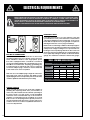
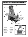
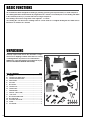
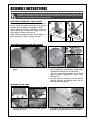
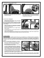
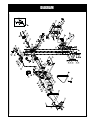
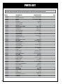
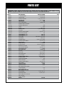
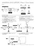
SETUP & OPERATION MANUAL FEATURES Two belt platens allowing for use with either 1” or 2” x 42” sanding belts. 1” OR 2” X 42” BELT & 8” DISC SANDER Steel ½ disc front guard. 1” and 2” 100 grit sanding belts and 8” 100 grit sanding disc included. Quick-change belt tension lever. Cast-aluminum belt guard with removable see-through top cover. Safety switch with removable lock-out key. Two built-in 1 1/2” dust ports. Large cast-aluminum tables. Miter guide included for disc table. On-board miter guide storage bracket. SPECIFICATIONS • Belt size 1” and 2” x 42” (25 and 50 x 1067 mm) • Belt speed 3100 fpm (930 mpm) • Belt table size 10 1/4” x 6” (260 x 152 mm) • Belt table tilt 45° (out) • Disc diameter 8” (200 mm) • Disc speed 3450 rpm • Disc table size 10 3/4” x 7” (273 x 178 mm) • Disc table tilt 10° (in) & 45° (out) • Dust ports (2) 1 1/2” (38 mm) • Motor M1 1/2 HP, 120 V, 1 Ph, 5.3 A • Weight (shipping / net) 42 lbs (19 kg) / 40 lbs (18 kg) Version #3_Revision #1 - (S/N0 150896714) - April 21, 2014 © Copyright General International MODEL # 15-142 M1 GENERAL® INTERNATIONAL 8360 Champ-d’Eau, Montreal (Quebec) Canada H1P 1Y3 Telephone (514) 326-1161 • Fax (514) 326-5555 • www.general.ca THANK YOU for choosing this General® International model 15-142 1” or 2” x 42” belt & 8” disc sander. This sander has been carefully tested and inspected before shipment and if properly used and maintained, will provide you with years of reliable service. For your safety, as well as to ensure optimum performance and trouble-free operation, and to get the most from your investment, please take the time to read this manual before assembling, installing and operating the unit. The manual’s purpose is to familiarize you with the safe operation, basic function, and features of this sander as well as the set-up, maintenance and identification of its parts and components. This manual is not intended as a substitute for formal woodworking instruction, nor to offer the user instruction in the craft of woodworking. If you are not sure about the safety of performing a certain operation or procedure, do not proceed until you can confirm, from knowledgeable and qualified sources, that it is safe to do so. Once you’ve read through these instructions, keep this manual handy for future reference. DISCLAIMER: The information and specifications in this manual pertain to the unit as it was supplied from the factory at the time of printing. Because we are committed to making constant improvements, General® International reserves the right to make changes to components, parts or features of this unit as deemed necessary, without prior notice and without obligation to install any such changes on previously delivered units. Reasonable care is taken at the factory to ensure that the specifications and information in this manual corresponds with that of the unit with which it was supplied. However, special orders and “after factory” modifications may render some or all information in this manual inapplicable to your machine. Further, as several generations of this model of sander and several versions of this manual may be in circulation, if you own an earlier or later version of this unit, this manual may not depict your unit exactly. If you have any doubts or questions contact your retailer or our support line with the model and serial number of your unit for clarification. GENERAL® INTERNATIONAL WARRANTY All component parts of General® International and Excalibur by General International® products are carefully inspected during all stages of production and each unit is thoroughly inspected upon completion of assembly. Limited Lifetime Warranty Because of our commitment to quality and customer satisfaction, General® International agrees to repair or replace any part or component which upon examination, proves to be defective in either workmanship or material to the original purchaser for the life of the tool. However, the Limited Lifetime Warranty does not cover any product used for professional or commercial production purposes nor for industrial or educational applications. Such cases are covered by our Standard 2-year Limited Warranty only. The Limited Lifetime Warranty is also subject to the “Conditions and Exceptions” as listed below. Standard 2-Year Limited Warranty All products not covered by our lifetime warranty including products used in commercial, industrial and educational applications are warranted for a period of 2 years (24 months) from the date of purchase. General® International agrees to repair or replace any part or component which upon examination, proves to be defective in either workmanship or material to the original purchaser during this 2-year warranty period, subject to the “conditions and exceptions” as listed below. To file a Claim To file a claim under our Standard 2-year Limited Warranty or under our Limited Lifetime Warranty, all defective parts, components or machinery must be returned freight or postage prepaid to General® International, or to a nearby distributor, repair center or other location designated by General® International. For further details call our service department at 1-888-949-1161 or your local distributor for assistance when filing your claim. Along with the return of the product being claimed for warranty, a copy of the original proof of purchase and a “letter of claim” must be included (a warranty claim form can also be used and can be obtained, upon request, from General® International or an authorized distributor) clearly stating the model and serial number of the unit (if applicable) and including an explanation of the complaint or presumed defect in material or workmanship. CONDITIONS AND EXCEPTIONS: This coverage is extended to the original purchaser only. Prior warranty registration is not required but documented proof of purchase i.e. a copy of original sales invoice or receipt showing the date and location of the purchase as well as the purchase price paid, must be provided at the time of claim. Warranty does not include failures, breakage or defects deemed after inspection by General® International to have been directly or indirectly caused by or resulting from; improper use, or lack of or improper maintenance, misuse or abuse, negligence, accidents, damage in handling or transport, or normal wear and tear of any generally considered consumable parts or components. Repairs made without the written consent of General® International will void all warranty. TABLE OF CONTENTS Rules for safe operation...................................................................................................... 5 Electrical requirements....................................................................................................... 6 Electrical connections......................................................................................................................................... 6 Circuit capacity................................................................................................................................................... 6 Extension cords.................................................................................................................................................... 6 Identification of main parts and components................................................................... 7 Basic functions ................................................................................................................... 8 Unpacking .......................................................................................................................... 8 List of contents...................................................................................................................................................... 8 Assembly instructions.................................................................................................... 9-10 Installing the sander on a stable surface......................................................................................................... 9 Installing the abrasive paper onto the disc..................................................................................................... 9 Installing the disc table....................................................................................................................................... 9 Installing the dust chute.................................................................................................................................... 10 Installing the belt table..................................................................................................................................... 10 Installing belt guard.......................................................................................................................................... 10 Connecting to a dust collector........................................................................................................................ 10 Basic adjustments and controls.................................................................................. 11-12 Connecting to a power source........................................................................................................................ 11 On/off power switch with safety key................................................................................................................ 11 Tilting the sanding belt/disc tables................................................................................................................. 11 Sanding belt tracking adjustment................................................................................................................... 12 Using the miter gauge....................................................................................................................................... 12 Maintenance..................................................................................................................... 13 Period maintenance......................................................................................................................................... 13 Required maintenance................................................................................................ 13-14 Sanding belt replacement/converting from 1” to 2” belts...................................................................... 13-14 Disc replacement.............................................................................................................................................. 14 Parts list & diagram..................................................................................................... 15-16 Contact information......................................................................................................... 18 RULES FOR SAFE OPERATION To help ensure safe operation, please take a moment to learn the machine’s applications and limitations, as well as potential hazards. General® International disclaims any real or implied warranty and hold itself harmless for any injury that may result from the improper use of it’s equipment. 1. Do not operate the sander when tired, distracted, or under the effects of drugs, alcohol or any medication that impairs reflexes or alertness. 2. The working area should be well lit, clean and free of debris. 3. Keep children and visitors at a safe distance when the sander is in operation; do not permit them to operate the sander. 4. Childproof and tamper proof your shop and all ma chinery with locks, master electrical switches and switch keys, to prevent unauthorized or unsupervised use. 12.Do not push or force the workpiece into the sander. The machine will perform better and more safe ly when working at the feed rate for which it was designed. 13.Avoid working from awkward or off balance posi tions. Do not overreach and keep both feet on floor. 14.Keep guards in place and in working order. If a guard must be removed for maintenance or clea ning, be sure it is properly re-attached before using the tool again. 15.Never leave the machine unattended while it is run ning or with the power on. 5. STAY ALERT! Give your work your undivided attention. Even a momentary distraction can lead to serious injury. 16.Use of parts and accessories NOT recommended by General® International may result in equipment malfunction or risk of injury. 6. Fine particulate dust is a carcinogen that can be hazardous to health. Work in a well-ventilated area and whenever possible use a dust collector and wear eye, ear and respiratory protection devices. 17.Never stand on the machine. Serious injury could occur if the sander is tipped over or if the sanding drums are unintentionally contacted. 7. Do not wear loose clothing, gloves, bracelets, necklaces or other jewelry while the sander is in operation. Wear protective hair covering to contain long hair and wear non-slip footwear. 8. Be sure that adjusting wrenches, tools, drinks and other clutter are removed from the machine and/or the feed table surface before operating. 9. Keep hands well away from the sanding belts and all moving parts. Use a brush, not hands, to clear away sanding dust. 10.Be sure sanding belts are securely installed on the sanding drums. 18.Always disconnect the tool from the power source before servicing, changing accessories or sanding belts, or before performing any maintenance or cleaning, or if the machine will be left unattended. 19.Make sure that switch is in the “OFF” position before plugging in the power cord. 20. Make sure the tool is properly grounded. If equipped with a 3-prong plug it should be used with a three- pole receptacle. Never remove the third prong. 21.Do not use the sander for any purpose other than its intended use. If used for other purposes, General® International disclaims any real or implied warranty and holds itself harmless for any injury, which may result from that use. 11.Do not operate the sander if the sanding belts are damaged or badly worn. 5 ELECTRICAL REQUIREMENTS BEFORE CONNECTING THE MACHINE TO THE POWER SOURCE, VERIFY THAT THE VOLTAGE OF YOUR POWER SUPPLY CORRESPONDS WITH THE VOLTAGE SPECIFIED ON THE MOTOR I.D. NAMEPLATE. A POWER SOURCE WITH GREATER VOLTAGE THAN NEEDED CAN RESULT IN SERIOUS INJURY TO THE USER AS WELL AS DAMAGE TO THE MACHINE. IF IN DOUBT, CONTACT A QUALIFIED ELECTRICIAN BEFORE CONNECTING TO THE POWER SOURCE. THIS TOOL IS FOR INDOOR USE ONLY. DO NOT EXPOSE TO RAIN OR USE IN WET OR DAMP LOCATIONS. EXTENSION CORDS A If you find it necessary to use an extension cord with your machine, use only 3-wire extension cords that have 3-prong grounding plug and a matching 3-pole receptacle that accepts the tool’s plug. Repair or replace a damaged extension cord or plug immediately. B C ELECTRICAL CONNECTIONS In the event of an electrical malfunction or short circuit, grounding reduces the risk of electric shock. The motor of this machine is wired for 120V single phase operation and is equipped with a 3-conductor cord and a 3-prong grounding plug A to fit a grounded type receptacle B. Do not remove the 3rd prong (grounding pin) to make it fit into an old 2-hole wall socket or extension cord. If an adaptor plug is used C, it must be attached to the metal screw of the receptacle. Note: The use of an adaptor plug is illegal in some areas. Check your local codes. If you have any doubts or if the supplied plug does not correspond to your electrical outlet, consult a qualified eletrician before proceeding. CIRCUIT CAPACITY Make sure that the wires in your circuit are capable of handling the amperage draw from your machine, as well as any other machines that could be operating on the same circuit. If you are unsure, consult a qualified electrician. If the circuit breaker trips or the fuse blows regularly, your machine may be operating on a circuit that is close to its amperage draw capacity. However, if an unusual amperage draw does not exist and a power failure still occurs, contact a qualified technician or our service department. 6 Make sure the cord rating is suitable for the amperage listed on the motor I.D. plate. An undersized cord will cause a drop in line voltage resulting in loss of power and overheating. The accompanying chart shows the correct size extension cord to be used based on cord length and motor I.D. plate amp rating. If in doubt, use the next heavier gauge. The smaller the number, the heavier the gauge. TABLE - MINIMUM GAUGE FOR CORD EXTENSION CORD LENGTH AMPERES 25 feet 50 feet 100 feet 150 feet AWG <5 18 16 16 14 6 to 10 18 16 14 12 10 to 12 16 16 14 14 12 to 16 14 12 *NR *NR *NR = Not Recommended IDENTIFICATION OF MAIN PARTS AND COMPONENTS FRONT VIEW D C B E O A F G J H I BELT SIDE VIEW A. BELT SANDER I. DISC TABLE B. SANDING BELT J. ON/OFF SWITCH C. BELT GUARD K. MITER GAUGE D. BELT GUARD L. COVER KNOBS WORK TABLE THUMBSCREW LOCK LEVER M. BELT TABLE E. BELT TENSION LEVER F. SANDING DISC N. DUST PORT G. SANDING DISC O. STEEL ½ DISC FRONT WORK TABLE H. RUBBER FOOT L K LOCK LEVER GUARD M N 7 BASIC FUNCTIONS This machine has been designed for sanding or polishing (removing kerf or pencil marks) on small workpieces. The sanding belt table can be tilted at any angle between 0º and 45° for bevelled pieces. Flat sanding, with table in the hoizontal position (0º), is easier and safer for longer workpieces. Belt sanding can be done using either of the supplied 1” or 2” belts. The sanding disc can be used for sanding round or curved surfaces. For angled sanding the disc table can be tilted from 10° inward to 45° outward. UNPACKING Carefully unpack and remove the unit and its components from its shipping container and check for missing or damaged items as per the list of contents below. B C NOTE: Please report any damaged or missing items to your General® International distributor immediately. A D LIST OF CONTENTS QTY A. SANDER..................................................................................... 1 B. SANDING DISC WORK TABLE................................................... 1 C. SANDING BELT WORK TABLE.................................................... 1 D. MITER GAUGE........................................................................... 1 E. DUST PORT................................................................................ 1 F. BELT GUARD.............................................................................. 1 G. SANDING DISC......................................................................... 1 H. SANIDING BELT......................................................................... 1 I. CARRIAGE BOLT........................................................................ 1 J. ALEN KEY (3 MM, 5 MM)......................................................... 2 K. 1” BELT PLATE............................................................................. 1 L. BELT GUARD THUMSCREW........................................................ 1 M. BELT TABLE LEVER...................................................................... 1 N. DISC TABLE LOCK LEVER.......................................................... 2 O. SCREW...................................................................................... 4 P. FLAT WASHER............................................................................. 4 8 E G H I F J K L N M O P ASSEMBLY INSTRUCTIONS BEFORE STARTING THE INSTALLATION AND ASSEMBLY, MAKE SURE THAT THE POWER SWITCH IS IN THE “OFF” POSITION AND THAT THE POWER CORD IS UNPLUGGED. DO NOT PLUG IN OR TURN ON THE SANDER UNTIL YOU HAVE COMPLETED THE INSTALLATION AND ASSEMBLY STEPS DESCRIBED IN THIS SECTION OF THE MANUAL. INSTALLING THE SANDER ON A STABLE SURFACE For your convenience this sander is shipped from the factory partially assembled and requires only minimal assembly and set up before being put into service. A B The unit should be installed on a flat, level, sturdy and stable surface, able to support the weight of the machine and the workpiece with ease, A. Never install or operate the sander over the edge of a table, workbench or other mounting surface, B. INSTALLING THE ABRASIVE PAPER ONTO THE DISC A B 1. Loosen Phillips screws as shown and remove disc guard. 2. Prepare the surface of the disc to receive the ad hesive sanding disc by wiping the surface with a rag dipped in mineral spirits or paint thinner. (Dispose of potentially flammable solvent-soaked rags according to manufacturer’s safety recommendations.) 3. Peel the protective backing from the abrasive paper, A, and stick the abrasive paper onto the disc, B. Re-install disc guard. INSTALLING THE DISC TABLE LEVER ON THE LEFT OF THE TABLE LEVER ON THE RIGHT OF THE TABLE A LEVER WASHER 1. Using 2 supplied ratchet levers and flat washers install the disc table. 2. Adjust/level the table manually and then tightenthe table mounting brackets A with a screwdriver 9 INSTALLING THE BELT TABLE A CARRIAGE BOLT 1. Install sanding belt table using the carriage bolt, flat washer, and ratchet lever as shown. Note: Make sure to position the trunnion over the alignment screw as shown, A. Align/level the table by hand and then using a 10 mm wrench and phillips head screwdriver tighten the table mounting brackets. Tip: using an 11 mm wrench, tighten the ratchet lever onto the carriage bolt at least a few turns until enough threads are engaged to allow tightening the lever by hand. INSTALLING THE DUST CHUTE INSTALLING BELT GUARD Install the dust chute to the bottom of the disc with a phillips head screw driver, as shown using the 4 supplied screws. Using the thumbscrew and rubber washer, install the see-through belt guard as shown. Note: Do not overtight- en the thumbscrew. CONNECTING TO A DUST COLLECTOR DO NOT OPERATE THIS SANDER WITHOUT AN ADEQUATE DUST COLLECTION SYSTEM PROPERLY INSTALLED AND RUNNING. OPERATING THIS SANDER WITHOUT ADEQUATE DUST COLLECTION CAN LEAD TO EQUIPMENT MALFUNCTION OR DANGEROUS SITUATIONS FOR THE OPERATOR OR OTHER INDIVIDUALS IN THE WORKSHOP. The two supplied 1 1/2” diameter dust outlets allow for connection to a dust collector (not included). Be sure to use appropriate sized hose and fittings (not included) and check that all connections are sealed tightly to help minimize airborne dust. If you do not already own a dust collection system consider contacting your General® International distributor for information on our complete line of dust collection systems and accessories or visit our Web Site at www.general.ca. ALWAYS TURN ON THE DUST COLLECTOR BEFORE STARTING THE SANDER AND ALWAYS STOP THE SANDER BEFORE TURNING OFF THE DUST COLLECTOR. 10 BASIC ADJUSTMENTS AND CONTROLS CONNECTING TO A POWER SOURCE TO REDUCE THE RISK OF SHOCK OR FIRE DO NOT OPERATE THE UNIT WITH A DAMAGED POWER CORD OR PLUG. REPLACE DAMAGED CORD OR PLUG IMMEDIATELY. SWITCH OFF TO AVOID UNEXPECTED OR UNINTENTIONAL START-UP, MAKE SURE THAT THE POWER SWITCH IS IN THE OFF POSITION BEFORE CONNECTING TO A POWER SOURCE. Once the assembly steps have been completed, uncoil the power cord and plug into an appropriate outlet. Refer back to the section entitled “Electrical Requirements” and make sure all requirements and grounding instructions are followed. When sanding operations have been completed turn off and unplug the sander from the power source. ON/OFF POWER SWITCH WITH SAFETY KEY This model 15-142 sander is equipped with an ON/OFF power switch with a removable lock out safety key: - To start the machine, insert the safety key, 1, and lift the switch up, 2. - To stop the machine, push the switch down, 3. (PREVENTS START-UP WHEN REMOVED) TO PREVENT UNWANTED OR UNAUTHORIZED START-UP OR USAGE, REMOVE THE LOCK-OUT KEY AND STORE IT IN A SAFE PLACE, OUT OF THE REACH OF CHILDREN, WHENEVER THE SANDER IS NOT IN USE. 1 2 3 SAFETY KEY POWER ON POWER OFF TILTING THE SANDING BELT/DISC TABLES BEFORE MAKING ANY ADJUSTMENTS, MAKE SURE THAT THE SWITCH IS IN THE “OFF” POSITION AND THAT THE POWER CORD IS UNPLUGGED. Table can tilt 10° inward to 45° outward LEVER ON THE LEFT OF THE TABLE TIGHTEN LOOSEN LOOSEN D C LEVER ON THE RIGHT OF THE TABLE TIGHTEN LOOSEN A B C TIGHTEN To tilt the sanding belt table: To tilt the sanding disc table: 1. Loosen table locking lever A. 1. Loosen table locking levers C. 2. Tilt the table to the desired angle B and then tighten the lever clockwise to secure the table in position. 2. Tilt the table to the desired angle D. Tighten the levers to secure the table in position. 11 SANDING BELT TRACKING ADJUSTMENT DO NOT PERFORM ANY ADJUSTMENTS WHILE THE MACHINE IS RUNNING. ALWAYS TURN OFF THE SANDER BEFORE PERFORMING ANY ADJUSTMENTS. KEEP HANDS WELL AWAY FROM THE SANDING BELT AND ALL MOVING PARTS WHEN THE SANDER IS RUNNING. Though not essential, proper belt tracking (having the belt running straight and turning as evenly on the rollers as possible) can prolong belt life and avoid having the belt slip off during operation. This is done by adjusting the angle of the lower roller slightly inwards or outwards, so that the belt does not drift off-center but stays on the middle of the rollers. Note: Belt tracking adjustments may be necessary after changing or replacing a sanding belt, to counterbalance for unevenness between sanding belts. Turn on the sander and let it run for a few seconds to visually confirm the belt tracking. If the belt is tracking straight and evenly on the middle of the rollers, you are ready to sand. Proceed with normal operations. If the belt is not tracking straight, follow the instructions below before proceeding with normal sanding operations. B 1. Loosen lock nut A using a 10 mm wrench. 2. Using the supplied 5 mm allen key turn the tracking adjustment bolt B. • Clockwise if the belt tracks to the right. • Counter-clockwise if the belt tracks to the left. Adjust gradually, no more than 1/4 turn at a time. A 3. Turn on the machine on for a few seconds and check the position of the belt on the rollers. 4. As needed, repeat this adjustment process until the belt is tracking evenly on the rollers. 5. Once belt tracking has been adjusted to your satisfaction re-tighten the lock nut A. USING THE MITER GAUGE A D The supplied miter gauge allows for easier and safer sanding by providing workpiece support when sanding straight (90°) or angled ends (0° to 45°). The miter gauge rides in the sanding disc table slot as shown in A and can be set to any angle up to 45° to the left or right B. To use a setting other than 90°, loosen the lock knob C by turning it counter-clockwise. Rotate the miter head to the required angle shown on the angle indicator and then turn the knob clockwise to tighten it. When not in use the miter gauge can be safely stowed on the storage bracket on the right side of the sander D. 12 C B MAINTENANCE MAKE SURE THE SANDER HAS BEEN TURNED OFF AND UNPLUGGED FROM THE POWER SOURCE BEFORE PERFORMING ANY MAINTENANCE. PERIODIC MAINTENANCE • Keep the machine CLEAN and FREE OF DUST. Vacuum or brush off any loose debris and wipe down the machine and the tables occasionally with a damp rag. • Rollers must always be kept clean. Dirt on rollers will cause poor tracking and belt slippage. • Periodically inspect the ON/OFF switch, power cord, plug and other parts for damage. DO NOT OPERATE THE SANDER WITH A DAMAGED SWITCH, POWER CORD, PLUG, OR OTHER PARTS. REPLACE A DAMAGED PART IMMEDIATELY. REQUIRED MAINTENANCE SANDING BELT REPLACEMENT/CONVERTING FROM 1” TO 2” BELTS Sanding belts should be replaced when worn out. Standard size 1” or 2” x 42” replacement belts and can be purchased in a variety of grits from your General® International dealer or (depending on availability) from your local tool, abrasives or sharpening supply dealer. These are standard sizes that should be readily available in most areas. The use of any other size is not recommended and can lead to serious injury and/or damage to the machine. Replace an installed worn sanding belt as follows: A B C D F Unscrew the lock knobs E 1. Remove the sanding belt work table by loosening the table bracket screws A unscrewing and removing the locking lever, washer and carriage bolt B. 2. Remove the belt guard C. 3. Unscrew the two lock knobs and remove the ma chine’s side cover D. 4. Turn the belt tension spring lever to loosen belt tension, attach it with the chain as shown F, and then remove the belt from the rollers E. 13 If switching to a belt of a different width: Flush 1. Using a 12 mm wrench unscrew and remove the belt platen bolt and washers and remove and set aside the belt platen. 2. Install the other size belt platen using the same bolt and washers. Make sure the front of the platen is flush with the slot below, so that the platen supports the belt without obstructing it. To install a new sanding belt: B 1. Fit the belt onto the two lower rollers and through the belt slot below the platen. Tip: To extend belt life and avoid premature breakage, take note of the direction arrows A printed on the inside of the sanding belt to make sure you install the belt in the correct direction. A 2. Make sure the belt tension spring lever is attached with the chain B to loosen belt tension, and then fit the belt onto the top roller. 3. Release the belt tension to lever to tighten the belt onto the rollers. 4. Turn the belt by hand several complete rotations to verify belt tracking (if needed complete belt tracking adjustments as shown on page 12). 5. With the belt tracking properly re-install the side cover, belt guard and the work table. Note: The platen that is not in use can be safely stowed in the storage mount on the left side of the sander. DISC REPLACEMENT Abrasive sanding discs should be replaced when worn out. Standard size 8” self-adhesive abrasive sanding discs can be purchased in a variety of grits from your General® International dealer or (depending on availability) from your local tool, abrasives or sharpening supply dealer. This is a standard size that should be readily available in most areas. The use of any other size is not recommended and can lead to serious injury and/or damage to the machine. Replace an installed worn sanding disc as follows: 1. Remove disc guard and peel the upper portion of the abrasive disc from the aluminum wheel A. A C 2. Slowly rotate the disc and continue to peel off until the entire abrasive disc comes free. 3. To remove any glue residue, grease or other impu rities that could interfere with proper adherence, wipe down the surface of the aluminum wheel with a rag dipped in mineral spirits or paint thinner. (Dispose of potentially flammable solvent-soaked rags B according to manufacturer’s safety recommendations.) 4. Peel the protective backing from the new abrasive paper B and stick the paper onto the aluminum wheel C. 5. Slowly rotate the disc and continue sticking the paper onto the disc, until the paper is fully installed, making sure to avoid leaving air pockets between the paper and the aluminum wheel. Re-install disc guard. 14 35 80 51 79 34 28 33 27 5 27 5 5 28 5 29 4 26 25 48 24 73 26 81 12 14 49 23 22 23 18 78 30 21 47 51 36 32 71 82 20 72 9 15 69 16 5 52 70 67 23 68 6 60 18 23 18 17 38 19 37 39 14 13 12 44 43 40 90 13 14 12 42 66 41 74 10 86 31 1 2 11 65 87 77 46 45 75 76 74 84 59 85 88 53 83 64 50 55 3 5 63 23 56 54 7 89 19 6 18 62 8 61 55 18 23 57 3 50 58 5 2 4 1 6 7 DIAGRAM DIAGRAM DIAGRAM 15 15 15 PARTS LIST IMPORTANT: When ordering replacement parts, always give the model number, serial number of the machine and part number. Also a brief description of each item and quantity desired. PART # DESCRIPTION 15142-01 STATOR 15142-02 MOTOR HOUSING 15142-03 ROTOR 15142-04 E CLIP 15142-05BEARING 15142-06 MOTOR COVER 15142-07 LOCK WASHER 15142-08 HEX. NUT 15142-09 PHILLIPS HEAD SCREW 15142-10 ROUND KEY 15142-11 ROUND KEY 15142-12 HEX. HEAD BOLT 15142-13 LOCK WASHER 15142-14 FLAT WASHER 15142-15 CORD CLAMP 15142-16 CARRIAGE BOLT 15142-17 TABLE BRACKET ( R ) 15142-18 HEX. NUT 15142-19 PHILLIPS HEAD SCREW 15142-20 BELT TABLE 15142-21 MACHINE BODY 15142-22 TABLE BRACKET ( L ) 15142-23 FLAT WASHER 15142-24 LOCKING LEVER 15142-25 DRIVE PULLEY 15142-26 SET SCREW 15142-27 C CLIP 15142-28 IDLER PULLEY 15142-29 PULLEY SHAFT 15142-30 UPPER BELT GUARD 15142-31 SET SCREW 15142-32 THUMB SCREW 15142-33 2” SANDING BELT 15142-34 BODY COVER 15142-35 LOCK KNOB 15142-36 ECCENTRIC SHAFT 15142-37 C CLIP 15142-38 PULLEY MOUNTING BASE 15142-39 CAP SCREW 15142-40 TENSION LEVER 15142-41 SPRING 15142-42 CAP SCREW 15142-43 CAP SCREW 15142-44PLATE 15142-45CAPACITOR 15142-46 SELF TAPPING SCREW 15142-47 2” PLATEN 15142-48 1” PLATEN 16 SPECIFICATIONQTY 123 X 57 X 50 1 126.5 X 1.8T X 151.5L 1 57 X 50 X19 X 282L 1 E-12 1 #6202ZZ 6 ADC-12 2 M5 4 M5 4 M5 X 167L 4 5 X 5 X 30L 1 5 X 5 X 25L 1 5/16” X 3/4” 7 5/16” 6 5/16” X 18 X 2T 7 6N-4 1 1/4” X 3-1/4”L 1 SPHC 1 M6 9 M6 X 16L 8 153 X 260 X 15 1 ADC-12 1 SPHC 1 1/4” X 16 X 1T 11 1/4” 1 88.2 X 14 X 51 1 M6 X 8L 2 S-15 2 88.2 X 35 X 51 2 19 X 15 X 84.65L 1 115.75 X 81 X 2.5T 1 M6 X 8L 1 M5 X 18L 1 2” X 42” X #100 1 ABS 1 1/4” X 27L 2 17 X 15 X 143.5L 1 S-17 1 ADC-12 1 M6 X 25L 1 ABS+15%GF 1 SWR 1 M5 X 10L 2 M5 X 16L 2 SK5 2 25UF/250V 1 M4 X 10L 1 SPCC 1 SPCC 1 PARTS LIST IMPORTANT: When ordering replacement parts, always give the model number, serial number of the machine and part number. Also a brief description of each item and quantity desired. PART # DESCRIPTION SPECIFICATION 15142-49 1” SANDING BELT 1” X 42”X #100 15142-50 LOCK LEVER 1/4” X 5/8L 15142-51 PLASTIC WASHER 1/4” X 16 X 1.6T 15142-52 MOTOR FAN 95 X 16 MM 15142-53 SWITCH BOX ABS 15142-54 ON / OFF SWITCH J-9301A, 4P 15142-55 MITER GAUGE ASSEMBLY 15142-55-1 MITER GAUGE BODY ABS 15142-55-2 T BAR 180L 15142-55-3 KNOB 1/4” X 27L 15142-55-4 FLAT WASHER 1/4” X 16 X 1.5T 15142-55-5POINTER SPHC 15142-55-6 PHILLIPS HEAD SCREW 5/32” X 1/4” 15142-55-7 SPROCKET WASHER M4 15142-56 TABLE BRACKET ( R ) ADC-12 15142-57 TABLE BRACKET ( L ) ADC-12 15142-58 DISC TABLE 190 X 273 X 15 X 2.8T 15142-59 SET SCREW M6 X 12L 15142-60 POWER CORD SJT18 X 3C X 2.0M 15142-61 PHILLIPS HEAD SCREW 3/16” X 3/8” 15142-62 DUST OUTLET ABS 15142-63 SANDING DISC 8” X #100 15142-64 8” DISC PLATE 203.2 X 13 X 27.5 15142-65 REAR DISC COVER ADC-12 15142-66 SELF TAPPING SCREW 3/16” X 1/2” 15142-67 MOUNTING PLATE SPHC 15142-68 HEX. HEAD BOLT 1/4” X 5/8” 15142-69 HEX. NUT 1/4” 15142-70 FOOT PAD 36 X 6 X 16T 15142-71 HEX. HEAD BOLT 3/8” X 3/4”L 15142-72 FLAT WASHER 3/8” X 19 X 2T 15142-73 PHILLIPS HEAD SCREW 3/16’ X 3/4”L 15142-74 CORD CLAMP 3/4” X 5/8” 15142-75 SPROCKET WASHER M5 15142-76 BRASS WASHER 5 MM 15142-77 PHILLIPS HEAD SCREW 3/16” X 1/4” 15142-78 CAP SCREW M4 X 6L 15142-79 3MM ALLEN KEY 3 MM 15142-80 5MM ALLEN KEY 5 MM 15142-81 BELT DIRECTION STICKER 15142-82 LOCK WASHER 3/8” 15142-83 CORD TERMINAL P2 15142-84 BELT TENSION STICKER 15142-85 FLAT WASHER 1/4” X 16 X 1T 15142-86 HEX. HEAD BOLT 1/4” X 3/8” L 15142-87 DISC DIRECTION STICKER 15142-88 DISC GUARD 15142-89 PHILLIP SCREW 15142-90 CHAIN SUS 304 QTY 1 2 3 1 1 1 1 1 1 1 1 1 1 1 1 1 1 1 1 4 1 1 1 1 3 1 4 4 4 2 2 3 2 1 1 1 2 1 1 1 2 2 1 1 1 1 1 3 1 17 8360 Champ-d’Eau, Montreal (Quebec) Canada H1P 1Y3 Tel.: (514) 326-1161 Fax: (514) 326-5565 - Parts & Service / (514) 326-5555 - Order Desk [email protected] www.general.ca Follow us: