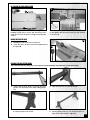
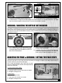
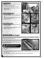
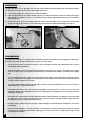
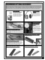
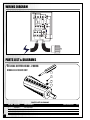
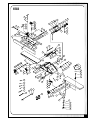
1
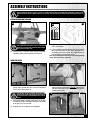
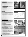
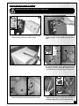
SETUP & OPERATION MANUAL
FEATURES
8” DELUXE JOINTER
Large surface, ground cast-iron tables for
stability and added support when feeding
longer stock.
Heavy-duty, three-knife cutter head for
clean, fast, superior finish cuts.
Jackscrew system for quick, easy knife
adjustment.
Large, heavy-duty, center-mounted castiron fence with 45°, 90° and 135° positive
stops.
Independent in-feed and out-feed table
adjustment hand wheels. Built-in rabbeting
ledge.
4” dust collection port.
Includes: 2 hand-paddle style push blocks
with onboard storage mounts.
Magnetic safety switch with overload protection.
Convenient front to back fence adjustment
hand wheel.
Motor mounted on vibro-eliminators for
smooth, quiet operation.
SPECIFICATIONS
TABLE SIZE
9 1⁄4’’ x 74 7⁄8’’ (235 x 1900 mm)
IN-FEED TABLE (L X W)
36 1⁄2’’ x 9 1⁄4’’ (936 x 235 mm)
OUT-FEED TABLE (L X W)
36 1⁄2’’ x 9 1⁄4’’ (936 x 235 mm)
MAXIMUM CUTTING WIDTH
8’’ (203 mm)
MINIMUM CUTTING DEPTH
1⁄2’’ (13 mm)
RABBETING CAPACITY
1⁄2’’ (13 mm)
FENCE SIZE
4’’ x 38’’ (102 x 965 mm)
CUTTER HEAD SPEED
5500 RPM
NUMBER OF KNIVES
3 / HELICAL
BASE DIMENSIONS (L X W)
29’’ x 17’’ (736.6 x 431.8 mm)
MOTOR
M1 - 2 HP, 220 V, 1 Ph, 12 A
M2 - 2 HP, 220 V, 3 Ph, 6 A
M3 - 2 HP, 600 V, 3 Ph, 3 A
MODEL
#80-200L
#80-200LHC
WEIGHT
572 LBS (260 kg)
REVISION 1 - JANUARY 28/10
© COPYRIGHT GENERAL INTERNATIONAL 01/2010
GENERAL® INTERNATIONAL
8360 Champ-d’Eau, Montreal (Quebec) Canada H1P 1Y3
Telephone (514) 326-1161 • Fax (514) 326-5555 • www.general.ca
THANK YOU
for choosing this General® International model 80-200L or
80-200LHC 8” Deluxe Jointer. This jointer has been carefully tested and inspected before shipment and if properly used and maintained, will provide you with years of reliable service. To
ensure optimum performance and trouble-free operation, and to get the most from your
investment, please take the time to read this manual before assembling, installing and operating the unit.
The manual’s purpose is to familiarize you with the safe operation, basic function, and features
of this jointer as well as the set-up, maintenance and identification of its parts and components. This manual is not intended as a substitute for formal woodworking instruction, nor to
offer the user instruction in the craft of woodworking. If you are not sure about the safety of
performing a certain operation or procedure, do not proceed until you can confirm, from
knowledgeable and qualified sources, that it is safe to do so.
Once you’ve read through these instructions, keep this manual handy for future reference.
Disclaimer: The information and specifications in this
manual pertain to the unit as it was supplied from the
factory at the time of printing. Because we are committed to making constant improvements, General®
International reserves the right to make changes to
components, parts or features of this unit as deemed
necessary, without prior notice and without obligation to
install any such changes on previously delivered units.
Reasonable care is taken at the factory to ensure that
the specifications and information in this manual corres-
ponds with that of the unit with which it was supplied.
However, special orders and “after factory” modifications may render some or all information in this manual
inapplicable to your machine. Further, as several generations of this model of jointer and several versions of this
manual may be in circulation, if you own an earlier or
later version of this unit, this manual may not depict your
machine exactly. If you have any doubts or questions
contact your retailer or our support line with the model
and serial number of your unit for clarification.
GENERAL® & GENERAL® INTERNATIONAL WARRANTY
All component parts of General®, General® International and Excalibur by General
International ® products are carefully inspected during all stages of production and each unit
is thoroughly inspected upon completion of assembly.
Limited Lifetime Warranty
Because of our commitment to quality and customer satisfaction, General® and General®
International agree to repair or replace any part or component which upon examination,
proves to be defective in either workmanship or material to the original purchaser for the life
of the tool. However, the Limited Lifetime Warranty does not cover any product used for professional or commercial production purposes nor for industrial or educational applications. Such
cases are covered by our Standard 2-year Limited Warranty only. The Limited Lifetime Warranty
is also subject to the “Conditions and Exceptions” as listed below.
Standard 2-Year Limited Warranty
All products not covered by our lifetime warranty including products used in commercial,
industrial and educational applications are warranted for a period of 2 years (24 months) from
the date of purchase. General® and General® International agree to repair or replace any
part or component which upon examination, proves to be defective in either workmanship or
material to the original purchaser during this 2-year warranty period, subject to the “conditions
and exceptions” as listed below.
To file a Claim
To file a claim under our Standard 2-year Limited Warranty or under our Limited Lifetime
Warranty, all defective parts, components or machinery must be returned freight or postage
prepaid to General® International, or to a nearby distributor, repair center or other location
designated by General® International. For further details call our service department at 1-888949-1161 or your local distributor for assistance when filing your claim.
Along with the return of the product being claimed for warranty, a copy of the original proof
of purchase and a “letter of claim” must be included (a warranty claim form can also be used
and can be obtained, upon request, from General® International or an authorized distributor)
clearly stating the model and serial number of the unit (if applicable) and including an explanation of the complaint or presumed defect in material or workmanship.
CONDITIONS AND EXCEPTIONS:
This coverage is extended to the original purchaser only. Prior warranty registration is not
required but documented proof of purchase i.e. a copy of original sales invoice or receipt
showing the date and location of the purchase as well as the purchase price paid, must be
provided at the time of claim.
Warranty does not include failures, breakage or defects deemed after inspection by General®
or General® International to have been directly or indirectly caused by or resulting from;
improper use, or lack of or improper maintenance, misuse or abuse, negligence, accidents,
damage in handling or transport, or normal wear and tear of any generally considered consumable parts or components.
Repairs made without the written consent of General® Internationallwill void all warranty.
TABLE OF CONTENTS
Rules for safe operation . . . . . . . . . . . . . . .5
Operating instructions . . . . . . . . .19-22
Additional Safety Instructions for Jointers . .6
Basic principles of jointing . . . . . . . . . . . . . . . . . . .19
Selecting boards suitable for jointing . . . . . . . . . .19
Determine the concave face and edge of your
board . . . . . . . . . . . . . . . . . . . . . . . . . . . . . . . . . . . .20
Adjust fence front to back position . . . . . . . . . . . .20
Checklist before starting . . . . . . . . . . . . . . . . . . . . .20
Connecting to a power source . . . . . . . . . . . . . . .21
Magnetic safety switch . . . . . . . . . . . . . . . . . . . . . .21
Overload protection . . . . . . . . . . . . . . . . . . . . . . . .21
Electrical requirements . . . . . . . . . . . . . . .7
Grounding instructions . . . . . . . . . . . . . . . . . . . . . . .7
Circuit capacity . . . . . . . . . . . . . . . . . . . . . . . . . . . . .7
Extension cords . . . . . . . . . . . . . . . . . . . . . . . . . . . . .7
Basic functions . . . . . . . . . . . . . . . . . . . . .8
Identification of main parts and components .8
Unpacking . . . . . . . . . . . . . . . . . . . . . . . . .9
Preparation and placement within the shop 10
Additional requirements for set up . . . . . . . . . . . .10
Clean up . . . . . . . . . . . . . . . . . . . . . . . . . . . . . . . . . .10
Placement within the shop . . . . . . . . . . . . . . . . . . .10
Establishing a safety zone . . . . . . . . . . . . . . . . . . .10
Assembly instructions . . . . . . . . .11-16
Attach the jointer bed to the base . . . . . . . . . . . .11
Install the V-belts . . . . . . . . . . . . . . . . . . . . . . . . . . . .12
Pulley parallel alignment . . . . . . . . . . . . . . . . . . . .12
Verify belt tension . . . . . . . . . . . . . . . . . . . . . . . . . .12
Install the cutter head guard . . . . . . . . . . . . . . . . .12
Attach the switch box / connect to the motor . .13
Install the fence and table height adjustment
handwheels . . . . . . . . . . . . . . . . . . . . . . . . . . . . . . .14
Install the dust port . . . . . . . . . . . . . . . . . . . . . . . . .14
Install the base door . . . . . . . . . . . . . . . . . . . . . . . .14
Re-position the fence locking handle . . . . . . . . .15
Install the fence tilt lever . . . . . . . . . . . . . . . . . . . . .15
Assemble the knife setting gauge . . . . . . . . . . . . .15
Connecting to a dust collector . . . . . . . . . . . . . . .16
Adjusting and setting the out-feed
table height . . . . . . . . . . . . . . . . . . . . . . .16
Adjusting and setting the in-feed table
height / depth of cut . . . . . . . . . . . . . . . . .16
Checking / adjusting the depth of cut
indicator . . . . . . . . . . . . . . . . . . . . . . . . .17
Adjusting the fence & checking /setting the
fence stops . . . . . . . . . . . . . . . . . . . . . . .17
Checking knives - model 80-200LHC only . . . . . . .18
Basic jointing operations . . . . . . . . . . . . .22
Surface planing . . . . . . . . . . . . . . . . . . . . . . . . . . . .22
Edge jointing . . . . . . . . . . . . . . . . . . . . . . . . . . . . . .22
Rabbeting . . . . . . . . . . . . . . . . . . . . . . . . . . . . . . . . .22
Maintenance . . . . . . . . . . . . . . . . . .23-26
Inspecting/replacing cutter head knives . . . . . .23
Knife setting or replacement
- model 80-200L only . . . . . . . . . . . . . . . . . . . . . . . . . . . .24
Helical cutter head insert reversal/
replacement - model 80-200LHC only . . . . . . . . . . . . .25
Adjusting the gibs . . . . . . . . . . . . . . . . . . . . . . . . . .26
Periodic maintenance . . . . . . . . . . . . . . . . . . . . . .26
Recommended optional accessories . . . . .27
Wiring Diagram . . . . . . . . . . . . . . . . . . . .28
Parts list & diagrams . . . . . . . . . . . . . .28-32
Contact information . . . . . . . . . . . . . . . . .34
RULES FOR SAFE OPERATION
To help ensure safe operation, please take a moment to learn the machine’s applications and limitations, as well as potential hazards. General® International disclaims any real or implied warranty and holds itself harmless for any injury that
may result from improper use of its equipment.
1. Do not operate this jointer when tired, distracted, or
under the effects of drugs, alcohol or any medication
that impairs reflexes or alertness.
13. Do not push or force stock into the cutter head. The
jointer will perform better and more safely when working at the rate for which it was designed.
2. The working area should be well lit, clean and free of
debris.
14. Be sure that the cutter head has gained full operating
speed before starting to joint.
3. Keep children and visitors at a safe distance when the
jointer is in operation; do not permit them to operate
the jointer.
15. Avoid working from awkward or off balance positions.
Do not overreach and keep both feet on floor.
4. Childproof and tamper proof your shop and all
machinery with locks, master electrical switches and
switch keys, to prevent unauthorized or unsupervised
use.
5. Stay alert! Give your work your undivided attention.
Even a momentary distraction can lead to serious
injury.
6. Fine particulate dust is a carcinogen that can be hazardous to health. Work in a well-ventilated area and
whenever possible use a dust collector. Wear face,
eye, ear, respiratory and body protection devices.
7. Do not wear loose clothing, gloves, bracelets, necklaces or other jewelry while the jointer is in operation.
Wear protective hair covering to contain long hair
and wear non-slip footwear.
8. Be sure that adjusting wrenches, tools, drinks and
other clutter are removed from the machine and/or
the table surface before operating.
9. Keep hands well away from knives and all moving
parts. Use a push stick to feed stock, and a brush, not
hands, to clear away chips and dust.
10. Be sure that the knives are securely installed in the cutterhead.
16. Keep guards in place and in working order. If a guard
must be removed for maintenance or cleaning be
sure it is properly re-attached before using the tool
again.
17. Use of parts and accessories NOT recommended by
GENERAL® INTERNATIONAL may result in equipment
malfunction or risk of injury.
18. Never stand on machinery. Serious injury could result
if the tool is tipped over or if the cutting tool is unintentionally contacted.
19. Always disconnect the tool from the power source
before servicing or changing accessories such as
knives, or before performing any maintenance or
cleaning, or if the machine will be left unattended.
20. Make sure that the switch is in the “OFF” position before
plugging in the power cord.
21. Make sure the tool is properly grounded. If equipped
with a 3-prong plug it should be used with a three-pole
receptacle. Never remove the third prong.
22. Do not use this jointer for other than its intended use. If
used for other purposes, GENERAL® INTERNATIONAL
disclaims any real implied warranty and holds itself
harmless for any injury, which may result from that use.
11. Always use clean, properly sharpened knives. Dirty or
dull knives are unsafe and can lead to accidents.
12. If using a power feeder, stop the feeder before stopping
the jointer.
5
Additional Safety
Instructions for Jointers
Because each shop situation is unique, no list of safety guidelines can ever be complete.
The most important safety feature of any shop is the knowledge and good judgement of the user. Use common
sense and always keep safety considerations, as they apply to your individual shop conditions, first and foremost
in mind. If you have any doubts about the safety of an operation you are about to perform: STOP! Do not perform
the operation until you have validated from qualified individuals if the operation is safe to perform and what is
the safest method to perform it.
1. WORK PIECE KICKBACK
Kickback is when the work piece is ejected at
high speeds from the jointer table by the force
of the cutter head. To minimize the risk of injury
from kickback, always use push blocks and
wear safety glasses. Do not operate this
machine if you do not understand kickback, its
causes and how to avoid it.
2. CUTTER HEAD ALIGNMENT
To reduce the risk of injury and to avoid kickback, keep the top edge of the outfeed table
aligned with the top dead center edge of the
knife.
3. PUSH BLOCKS
Always use push blocks when jointing. Never
pass your bare hands directly over the cutter
head without a push block to hold and guide
the workpiece.
4. WORKPIECE SUPPORT
To make safe cuts and reduce the risk of injury,
support the workpiece adequately at all times.
Never attempt to make a cut with an unstable
workpiece.
5. KICKBACK ZONE
The kickback zone on a jointer is the area
directly in the path through and off of the end
of the infeed table. Never stand or allow others
to stand in this area during operation.
6
6. MAXIMUM DEPTH OF CUT
The maximum depth of cut for one pass is 1/8”.
Never attempt to remove more material than
1/8” in any single pass.
7. JOINTING WITH THE GRAIN
Jointing against the grain or jointing end grain
is dangerous and could produce chatter or
excessive chip out. Always joint with the grain.
8. KEEPING GUARDS IN PLACE
Except when rabbeting, all operations must be
performed with the guard in place. After
rabbeting, be sure to replace the guard.
9. PROPER CUTTING
Always move the work piece over the cutter
head from the infeed table towards the outfeed
table until the work piece has passed completely over the cutter head. Never back the
work piece towards the infeed table.
10. USING GOOD WORK PIECE STOCK
Jointing safety begins with the stock used with
the machine. Inspect the work piece carefully
before jointing it. Never joint a board that has
loose knots, staples, nails or other embedded
foreign objects. If you have the slightest doubt
about the structural integrity or stability of a
board: Do Not Joint It.
ELECTRICAL REQUIREMENTS
BEFORE CONNECTING THE MACHINE TO THE POWER SOURCE, VERIFY THAT THE VOLTAGE OF YOUR POWER SUPPLY CORRESPONDS
WITH THE VOLTAGE SPECIFIED ON THE MOTOR I.D. NAMEPLATE. A POWER SOURCE WITH GREATER VOLTAGE THAN NEEDED CAN
RESULT IN SERIOUS INJURY TO THE USER AS WELL AS DAMAGE TO THE MACHINE. IF IN DOUBT, CONTACT A QUALIFIED ELECTRICIAN
BEFORE CONNECTING TO THE POWER SOURCE.
THIS TOOL IS FOR INDOOR USE ONLY. DO NOT EXPOSE TO RAIN OR USE IN WET OR DAMP LOCATIONS.
NOTE: VOLTAGE REQUIREMENTS AND AMPERAGE DRAW FOR M2 & M3 3-PHASE MOTORS MAY NOT BE FULLY
DESCRIBED IN THIS MANUAL. FOR COMPLETE ELECTRICAL REQUIREMENTS REFER TO THE MOTOR I.D. NAME PLATE ON
THE MACHINE. IF IN DOUBT CONSULT A LICENSED QUALIFIED ELECTRICIAN BEFORE PROCEEDING.
EXTENSION CORDS
C
A
B
GROUNDING INSTRUCTIONS
In the event of an electrical malfunction or short circuit,
grounding reduces the risk of electric shock to the operator. The motor of this machine is wired for 220V single
phase operation and is equipped with a 3-conductor
cord A and a 3-prong grounded plug B to fit a matching grounding type receptacle C.
The use of an extension cord is not generally recommended for 220V equipment. If you find it necessary,
use only 3-wire extension cords that have 3-prong
grounding plug and a matching 3-pole receptacle that
accepts the tool’s plug. Repair or replace a damaged
extension cord or plug immediately.
If you find it necessary to use an extension cord with
your machine make sure the cord rating is suitable for
the amperage listed on the motor I.D. plate. An undersized cord will cause a drop in line voltage resulting in
loss of power and overheating. The accompanying
chart shows the correct size extension cord to be used
based on cord length and motor I.D. plate amp rating.
If in doubt, use the next heavier gauge. The smaller the
number, the heavier the gauge.
TABLE - MINIMUM GAUGE FOR CORD
TOTAL LENGTH OF CORD IN FEET
AMPERE
RATING
<5
DO NOT MODIFY THE PLUG PROVIDED ! If it will not fit your recepta-
6 TO 10
cle, have the proper receptacle installed by a qualified
electrician.
10 TO 12
12 TO 16
CHECK with a qualified electrician or service person if
you do not completely understand these grounding
instructions, or if you are not sure the tool is properly
grounded.
220 VOLTS 50 FEET
------->
------->
------->
------->
100 FEET 200 FEET 300 FEET
18
AWG
16
16
14
18
16
14
12
16
16
14
12
14
12
* NR
* NR
* NR = Not Recommended
CIRCUIT CAPACITY
Make sure that the wires in your circuit are capable of
handling the amperage draw from your machine, as
well as any other machines that could be operating on
the same circuit. If you are unsure, consult a qualified
electrician. If the circuit breaker trips or the fuse blows
regularly, your machine may be operating on a circuit
that is close to its amperage draw capacity. However, if
an unusual amperage draw does not exist and a
power failure still occurs, contact a qualified technician
or our service department.
7
8” DELUXE JOINTER
80-200L & 80-200LHC
BASIC FUNCTIONS
This 8” jointer is designed for face and edge jointing in solid wood only. The unit is not designed nor should it be
used to surface or prepare, plywood, wood panelling, particleboard, MDF nor any other wood based by-products
nor any non-wood based materials.
This 8” jointer is offered with 2 different cutter head options as follows:
• Model 80-200L M1 – 8” jointer with standard 3-knife cutter head;
• Model 80-200LHC M1 - 8” jointer with “Byrd” style helical cutter head with reversible four-sided carbide inserts.
IDENTIFICATION OF MAIN PARTS AND COMPONENTS
OUTFEED TABLE
RABBETING ARM
CUTTER HEAD GUARD
FENCE ASSEMBLY
INFEED TABLE
OUT-FEED TABLE
ADJUSTMENT
HANDWHEEL
DEPTH OF CUT
INDICATOR
IN-FEED TABLE ADJUSTMENT
HANDWHEEL
TABLE LOCKING LEVERS
PUSH BLOCKS
MAGNETIC SWITCH
BASE WITH MOTOR
REAR VIEW
90º FENCE STOP BOLT
FENCE TILT LEVER
TABLE DEPTH
ADJUSTMENT
LOCK PIN
FENCE ADJUSTMENT
HANDWHEEL
8
FENCE LOCK LEVER
(TILT)
FENCE LOCK LEVER
(MOVING)
UNPACKING - MODELS 80-200L & 80-200LHC
Carefully unpack and remove the unit and its components from its shipping crate and check for missing or damaged items as per the list of contents below.
NOTE: Please report any damaged or missing items to your GENERAL® INTERNATIONAL distributor immediately.
LIST OF CONTENTS
QTY
A B C D E F G* H I
J** -
JOINTER ASSEMBLY W/FENCE..........................................1
CUTTER HEAD GUARD.......................................................1
DUST PORT.........................................................................1
4” HAND WHEEL ................................................................1
6” HAND WHEEL ................................................................2
FENCE TILT LEVER ..............................................................1
BASE...................................................................................1
MAGNETIC SAFETY SWITCH..............................................1
V-BELT.................................................................................2
KNIFE SETTING GAUGE
Knife setting gauge rod .................................................1
Knife setting gauge foot ................................................2
E-clip .................................................................................4
K - PUSH BLOCK .....................................................................2
LBASE DOOR.......................................................................1
M - MOUNTING BOLT ..............................................................3
N - LOCK WASHER ..................................................................3
O
P
Q
- FLAT WASHER.....................................................................4
- PHILLIPS HEAD SCREW ......................................................4
- TOOLS
8-10 mm open end wrench...........................................1
12-14 mm open end wrench.........................................1
17-19 mm open end wrench.........................................1
3 mm Allen key................................................................1
4 mm Allen key................................................................1
5 mm Allen key................................................................1
R*** - HELICAL CUTTER HEAD TOOLS/REPLACEMENT PARTS
Screw ..............................................................................10
Carbide insert .................................................................5
Star point screw driver ....................................................2
*
The safety switch is not already installed on the base.
**
Not included or required on “HC” model.
***
Included on “HC” model only.
G
A
D
*
E
C
H
F
B
J **
L
K
I
M
O
P
R ***
Q
N
9
PREPARATION AND PLACEMENT WITHIN THE SHOP
ADDITIONAL REQUIREMENTS FOR SET UP
•
•
•
•
•
3 Extra people to assist with lifting
Straightedge
45º & 90º combination square
Phillips Screwdriver
Pliers or Vise-grips
X3
CLEAN UP
The protective coating on the jointer tables prevents rust from forming during shipping and storage. Remove it by
rubbing with a rag dipped in kerosene, mineral spirits or paint thinner. (Dispose of potentially flammable solventsoaked rags according to manufacturer’s safety recommendations.)
A putty knife, held flat to avoid scratching the surface, may also be used to scrape off the coating followed by
clean-up with solvent. Avoid rubbing the saw’s painted surfaces, as many solvent-based products will remove paint.
To prevent rust, apply a light coating of paste wax or use regular applications of any after-market surface protectant or rust inhibitor.
PLACEMENT WITHIN THE SHOP
THIS MODEL 80-200L/LHC JOINTER IS HEAVY – 572 LBS (260 KG). DO NOT OVER-EXERT. THE HELP OF OF AT LEAST THREE ASSISTANTS, A HOIST OR FORKLIFT WILL BE NEEDED FOR THE FOLLOWING STEP.
TO LIMIT THE RISK OF SERIOUS INJURY OR DAMAGE TO THE MACHINE, ANY EQUIPMENT USED TO LIFT THIS MACHINE (HOIST OR
FORKLIFT) SHOULD HAVE A RATED CAPACITY IN EXCESS OF 572 LBS - 260 KG.
This machine should be installed and operated only on a
solid, flat and stable floor that is able to support the
weight of the jointer and the operator.
Using the dimensions shown as a guideline, plan for placement within your shop that will allow the operator to
work unencumbered and unobstructed by foot traffic
(either passing shop visitors or other shop workers) or
other tools or machinery.
ESTABLISHING A SAFETY ZONE
For shops with frequent visitors or multiple operators, it is
advisable to establish a safety zone around shop
machinery. A clearly defined “no-go” zone on the floor
around each machine can help avoid accidents that
could cause injury to either the operator or the shop visitor. It is advisable to take a few moments to either paint
(using non-slip paint) or using tape, define on the floor the limits or perimeter of each machines safety zone. Take
steps to ensure that all operators and shop visitors are aware that these areas are off limits whenever a machine is
running for everyone but the individual operating the unit.
10
ASSEMBLY INSTRUCTIONS
SERIOUS PERSONAL INJURY COULD OCCUR IF YOU CONNECT THE MACHINE TO THE POWER SOURCE BEFORE YOU HAVE COMPLETED THE INSTALLATION AND ASSEMBLY STEPS. DO NOT CONNECT THE MACHINE TO THE POWER SOURCE UNTIL INSTRUCTED TO DO
SO.
ATTACH THE JOINTER BED TO THE BASE
A
THE JOINTER BED IS VERY HEAVY. DO NOT OVER-EXERT.
THE HELP OF AT LEAST THREE ASSISTANTS WILL BE NEEDED FOR THE FOLLOWING STEP.
1.
C
B
Using a hoist or with the help of three assistants,
carefully lift the jointer bed onto the base A.
2. Align the 3 bolt holes on the jointer bed with the 3
holes on the base.
3. Use the supplied mounting bolts with lock washers
B to bolt the jointer to the base through the 3
mounting holes from inside the cabinet and up
into the bottom of the jointer bed C.
Note: Only hand-tighten the bolts for now. Final tightening
will be done after pulley alignment.
INSTALL THE V-BELTS
C
B
1.
D
A
Loosen and remove knob A, then remove the
upper pulley guard B to give yourself unimpeded
access to the upper pulley C.
PULL SLOWLY - DO NOT USE SHARP TUGS! KEEP YOUR
LOWER HAND FAR ENOUGH ABOVE THE MOTOR PULLEY
TO AVOID PINCHING HAND BETWEEN THE BELT AND THE
PULLEY.
2.
Place a V-belt on the inner groove on the upper
pulley D, then fit and hold a portion of the opposite end of the belt into the corresponding groove
on the motor pulley.
E
F
3. Using both hands, carefully pull down on the belt
to rotate the pulleys and allow the belt to seat itself
in the groove, as shown in E.
4.
Repeat step 3 to install the second belt F.
11
PULLEY PARALLEL ALIGNMENT
1.
Hold a straight edge flush to the face of the upper
pulley A to check alignment with the lower pulley,
B.
–
If the pulleys are aligned: Fully tighten the bolts
that secure the jointer bed to the stand.
–
If the pulleys are not aligned: Adust the position of
the jointer bed on the base to obtain pulley alignment then fully tighten the bolts that secure the
jointer bed to the stand.
A
B
C
D
UPPER PULLEY
LOWER PULLEY
Note: If pulley alignment cannot be obtained, loosen both set screws C located on the upper pulley and slide the pulley
on its shaft D to obtain parallel alignment then re-tighten the set screws.
VERIFY BELT TENSION
1.
Push on the belts with your finger. The belts should not
move more than 1/2".
2.
If needed, tighten the belts by loosening the 4 motor
bracket mounting bolts and lowering the bracket
along the slotted holes, then re-tightening the bolts.
Push down while
re-tightening bolts
INSTALL THE CUTTER HEAD GUARD
C
Tension is maintained on the cutter head guard using
a spring loaded knob on the underside of the rabbetting arm. The tension causes the guard to automatically snap back against the fence and cover the knives
once the workpiece has cleared the guard.
To install the guard:
1.
B
Remove the set screw A on the guard shaft.
Turn and hold the tension adjustment knob and fit
the shaft as far as it will go down into the mounting
hole on the rabbeting arm at the front of the jointer C.
Note: The c-clip B on the shaft will keep the guard at the
A
2.
D
correct height above the tables.
3.
To test the tension, pull back on the guard bringing
it away from the table and release.
4.
If you find the tension on the guard does not snap
the guard back firmly enough, hold the tension
adjustment knob and remove the guard.
5.
Turn the tension adjustment knob another 1/2 turn
and re-install the guard.
6.
Test the tension again and repeat steps 4 and 5
until adequate tension if achieved.
7.
Tighten the stop screw on the bottom of the shaft D to secure the guard in place.
12
ATTACH THE SWITCH BOX / CONNECT TO THE MOTOR
MAKE SURE THAT THE JOINER IS NOT CONNECTED TO A POWER SOURCE.
A
1.
B
Loosen the two plastic screws A on the front of the
switch box then remove the white cover B.
2.
Attach the switch box to the right side of the base
cabinet using the screws already mounted on the
base.
E
C
D
3.
Re-install the switch box cover.
G
3.
H
I
J
F
4.
Run the power cord (with the strain relief attached
C) from the bottom of the switch box into the
opening in the base cabinet D making sure the
cord reaches the connection box E on the motor.
Loosen and remove the screw at the bottom of the
motor connection box F and remove the cover G.
5.
Attach the wires H and replace the cover using the
supplied strain relief I to secure the cord in the
opening at the bottom of the connection box J.
13
INSTALL THE FENCE AND TABLE HEIGHT ADJUSTMENT HANDWHEELS
B
C
A
1.
Fit the fence adjustment handwheel (the smallest
one) A on the shaft on the rear fence bracket. The
slots in the handwheel must be aligned with the
spring pin on the shaft, B.
2.
Using the supplied 3 mm Allen key, tighten the set
screw on the shaft (under the wheel) to secure the
handwheel to the shaft.
1
3.
Repeat steps 1 and 2 with the two big handwheels
on the shafts at the front of the machine
INSTALL THE DUST PORT
A
B
Note: The table height adjustment handwheels are equipped with spring loaded flip up handles to allow you to
minimize the obstruction the handwheels may cause during jointing operations.
INSTALL THE BASE DOOR
A
4X
Attach the dust port A to the left side of the base using
the supplied screws and flat washers B.
Note:
Four brackets are already installed on the right side of the
base for convenient onboard storage of the 2 hand-paddle
style push blocks supplied.
14
2
Install the base door A on the base as shown in B.
B
RE-POSITION THE FENCE LOCKING LEVER
C
A
D
B
For shipping purposes the fence locking lever is
installed upside down. Loosen and remove the lock
nut A and remove the fence locking lever B and flat
washer.
Re-install the locking lever with flat washer as shown in
C and tighten with the lock nut, the lock nut oriented
as shown in D.
INSTALL THE FENCE TILT LEVER
1.
Thread the knob on the fence tilt lever A.
2.
Screw the fence tilt lever into the threaded hole in
the fence B.
B
A
ASSEMBLE THE KNIFE SETTING GAUGE
Note: Model 80-200L only. This gauge is not required on model 80-200LHC due to the helical cutter head design.
1.
Using a pair of pliers, push a c-clip into the inner
grooves on each end of the knife setting gauge
rod.
2.
Slide one foot onto one end of the rod.
3.
Secure the foot on the rod by pushing a c-clip into
the exposed groove in the rod.
4.
Repeat step 2 and 3 to install the other foot.
5.
Set the gauge aside for use whenever knife settings need to be verified or adjusted.
15
CONNECTING TO A DUST COLLECTOR
A dust port with a 4” opening is provided to accommodate connection to a dust collector (not included).
Once the dust port has been installed, be sure to use
appropriate sized hose and fittings (not included) and
check that all connections are sealed tightly to help minimize airborne dust.
If you do not already own a dust collection system
consider contacting your General® International distributor for information on our complete line of dust
collection systems and accessories or visit our Web Site
at www.general.ca.
ADJUSTING AND SETTING THE OUT-FEED TABLE HEIGHT
The out-feed table should be set level with the highest point of the knives A. The height of the out-feed table should
be verified and ajusted prior to first use. It should also be verified and re-adjusted periodically to compensate for
knife wear and also upon knife replacement.
A
ALWAYS DISCONNECT THE MACHINE FROM THE
POWER SOURCE BEFORE MAKING ANY ADJUSTMENTS. FAILURE TO HEED THIS WARNING CAN
LEAD TO SERIOUS PERSONAL INJURY.
IN-FEED
OUT-FEED
(left) Table
(right) Table
1. Make sure that the the machine is disconnected from the
power source.
2. To give yourself unimpeded access to the cutter head
and upper pulley, remove the cutter head guard and
fence.
3. Set a straightedge onto the out-feed table so that it
sits over the cutter head but does not completely
cross the gap between the tables and touch the infeed table A.
4. Turn the upper pulley by hand, until any one of the
knives is at it’s highest point.
5.
Loosen table locking lever B .
6.
Use hand wheel C to adjust the out-feed table
height so that the knife barely touches the straightedge.
7.
B
C
Re-tighten locking lever B to secure the out-feed table
in position.
ADJUSTING AND SETTING THE IN-FEED TABLE HEIGHT / DEPTH OF CUT
The depth of cut is set by raising or lowering the in-feed
table.
WORKPIECE
Refer to the recommended depth of cut settings in section
“Basic Jointing Operations Instructions”, on page 22.
THE MAXIMUM DEPTH OF CUT FOR ONE PASS IS
1/8”. NEVER ATTEMPT TO REMOVE MORE MATERIAL
THAN 1/8” IN ANY SINGLE PASS.
ALWAYS DISCONNECT THE MACHINE FROM THE
POWER SOURCE BEFORE MAKING ANY ADJUSTMENTS. FAILURE TO HEED THIS WARNING CAN
LEAD TO SERIOUS PERSONAL INJURY.
16
DEPTH OF CUT
REAR VIEW
A
C
B
Important! Never adjust the table height with the lock-pin
engaged as this will break the pin.
2.
Pull & hold back the1/8” depth stop lock-pin B.
1.
Loosen the in-feed table height locking lever A.
3.
Use hand wheel C to adjust in-feed table height to the desired depth of cut and then release the 1/8” depth
stop lock-pin and re-tighten locking lever A to secure the in-feed table in position.
CHECKING / ADJUSTING THE DEPTH OF CUT INDICATOR
The depth of cut indicator has been factory set to read “0” when the in-feed table is at the exact same height as the
highest point of the cutterhead. However we recommend that you verify that the depth of cut indicator is properly set
prior to first use. Also, with use and vibration over time, it may eventually become necessary to re-adjust the depth of
cut indicator as follows:
A
D
B
OUT-FEED
(left) Table
IN-FEED
(right) Table
C
1.
Set a straightedge onto the in-feed table so that
it sits over the cutter head without completely
crossing the gap between the tables to touch or sit
above the out-feed table A.
2.
Raise or lower the in-feed table until it is level highest point of the cutterhead B.
3.
If needed, loosen the 2 screws C and adjust the
pointer left or right until the pointer is set to the zero
point on the scale D, then retighten the screws.
ADJUSTING THE FENCE & CHECKING / SETTING THE FENCE STOPS
The fence stops allow you to position the fence at specific pre-set angles in relation to the tables without having to
measure each time you return to that angle.
Due to wear and vibration, fence stops can over time
become misaligned and should be checked periodically
and re-set if necessary.
To move the fence front to back:
B
1. Loosen locking lever A.
2. Position the fence over the cutter head as needed.
3. Re-tighten locking lever A.
A
To tilt the fence:
1. Loosen locking lever B.
2. Set the fence 45° inward or 45° inward
3. Re-tighten locking lever B.
17
To set the 90° fence stop:
1. Using a 90° combination or machinists square, set the
fence to 90° C.
C
2. Flip the 90° stop into position D.
3. Loosen the jam nut E on the 90° fence stop bolt.
4. Adjust the 90° fence stop bolt F until it makes contact
with the 90° stop.
F
90°
5. Retighten the jam nut.
D
E
To set the 45° outward fence stop:
G
1. Using a combination or machinists square, set the
fence to 45° outward G.
2. Loosen the jam nut H on the 45° outward fence stop
bolt.
I
3. Adjust the 45° outward fence stop bolt I until it makes
contact with the back of the fence.
H
4. Retighten the jam nut.
To set the 45° inward fence stop:
K
J
1. Using a 45° combination or machinists square, set the
fence to 45° inward J.
M
L
2. Loosen the jam nut K.
3. Adjust the 45° inward fence stop nut L until it makes
contact with the 45° inward stop M.
4. Retighten the jam nut.
CHECKING KNIVES (80-200L ONLY)
The knives have been factory set to the exact same height in the cutter head. However we suggest that you verify that
the knives are properly set prior to first use.
Accurate work results can only be achieved when all three
knives are properly installed and set to the exact same height
in the cutter head. To verify if the knives are set properly, use
the supplied knife setting gauge A following the steps below
for each of the three knives:
A
ALWAYS DISCONNECT THE MACHINE FROM THE
POWER SOURCE BEFORE MAKING ANY ADJUSTMENTS. FAILURE TO HEED THIS WARNING CAN
LEAD TO SERIOUS PERSONAL INJURY.
1. Make sure that the the machine is disconnected from the
power source.
2. To give yourself unimpeded access to the cutter head and knives, remove the blade guard.
3. Using the table height adjustment hand wheels, lower the tables enough to allow the knife setting gauge to fit fully
on the cutter head.
4. Remove the fence to have access to the upper pulley and turn it by hand to rotate the cutter head.
18
5. Set the gauge onto the cutter head with the center reference pads of the gauge sitting directly above a knife.
B
6. Observe how the gauge sits on the cutter head and
how/if the knife touches the center reference pads. The
ideal position has both sets of feet of the gauge sitting
flush on the cutter head and the knife barely touching the
center reference pads on the gauge B.
7. Should any (or all) of the knives not be set properly, follow the instructions in section “Knife Setting or Replacement”, on page 24.
OPERATING INSTRUCTIONS
BASIC PRINCIPLES OF JOINTING
This jointer is designed to remove material from the bottom face of a board in order to bring one face of the board
(or a series of boards) perfectly flat A.
This perfectly flat face is then placed against the fence, set at 90º to the tables, to obtain a perfectly perpendicular
90º flat edge B.
This jointer is not intended (and should not be used) to joint any material other than solid wood.
B
A
SELECTING BOARDS SUITABLE FOR JOINTING
C
1. Jointing safety begins with the stock used with the
machine. Inspect the work piece carefully before
jointing it. Never joint a board that has loose knots,
staples, nails or other embedded foreign objects. If
you have the slightest doubt about the structural
integrity or stability of a board: Do Not Joint It.
2. Only boards with the grain running more or less lengthwise are suitable for jointing C.
ALWAYS JOINT IN THE GENERAL DIRECTION OF THE GRAIN. JOINTING AGAINST THE GRAIN OR JOINTING END GRAIN
IS DANGEROUS AND MAY CAUSE THE WORKPIECE TO SHATTER.
19
DETERMINE THE CONCAVE FACE AND EDGE OF YOUR BOARD
Place your board on a flat surface to identify its concave face D and edge E. The boards must be jointed with its
concave face and edge against the jointer table.
D
E
ADJUST FENCE FRONT TO BACK POSITION
To limit your exposure to the knives in the cutter head, never take more knife length than is required to complete
the cut. Set the position of the fence so that the length of blade remaining exposed is roughly 1/4” longer than the
width of the board to be jointed.
1/4”
FACE JOINTING
1/4”
EDGE JOINTING
CHECKLIST BEFORE STARTING
VERIFY ALL CHECK POINTS BEFORE STARTING. FAILURE TO COMPLY CAN RESULT IN SERIOUS INJURIES.
20
•
Make sure you and any assistants are wearing safe appropriate workshop attire. Roll up long sleeves, secure
long hair and remove any jewelry: watches, rings, bracelets or anything that could become caught in the moving parts, potentially causing serious injury.
•
Make sure the board has been inspected and is suitable for jointing as explained in the previous section
“Selecting boards suitable for jointing”.
•
Verify that the cutter head guard is functioning properly (snaps back against the fence and covers the knives).
•
Make sure that the fence is properly set and locked in place.
•
Make sure to have on safety glasses as well as hearing and respiratory protection at all times when using the
jointer.
CONNECTING TO A POWER SOURCE
TO REDUCE THE RISK OF SHOCK OR FIRE DO NOT
OPERATE THE UNIT WITH A DAMAGED POWER
CORD OR PLUG. REPLACE DAMAGED CORD OR
PLUG IMMEDIATELY.
SWITCH OFF
TO AVOID UNEXPECTED OR UNINTENTIONAL
START-UP, MAKE SURE THAT THE POWER SWITCH IS
IN THE OFF POSITION BEFORE CONNECTING TO A
POWER SOURCE.
Once the assembly and adjustment steps have been completed, uncoil the power cord and plug it into an appropriate
outlet. Refer back to the section entitled “ELECTRICAL REQUIREMENTS” and make sure all requirements and grounding
instructions are followed.When jointing operations have been
completed unplug the jointer from the power source.
MAGNETIC SAFETY SWITCH
D
A
This model 80-200L/LHC jointer is equiped with a MAGNETIC SAFETY SWITCH A designed to protect the unit
and the user from power surges, power outages and
unwanted or unintentional start-up.
The switch assembly is equipped with a GREEN “START”
button B and a RED spring loaded “STOP” button C.
B
Once the RED “STOP” button has been pressed, the
machine can only be started by turning the BLACK
inner part of the button to the right to release the stop
button, D.
B
OVERLOAD PROTECTION
The magnetic safety switch on this jointer is equipped with an overload protection feature. To prevent an electrical
overload from damaging the motor, in the event of a spike in line voltage or amperage draw, the internal overload
protector will automatically be tripped, thereby cutting off power to the motor. To reset the overload protection
switch after it has been tripped proceed as follows:
Note: The most common causes of such overloads are:
1.
2.
3.
Overworking the motor by attempting to remove too much material in one single pass or by feeding the workpiece too quickly, thereby causing an increase in power consumption and a spike in amperage draw.
An electrical extension cord that is too long or not the correct gauge of wire, which can also cause an increase
in amperage draw. If an electric extension cord must be used, follow the instructions and refer to the chart in
the electrical requirements section at the beginning of this manual.
Overworked circuit caused by operating on a circuit that is close to its amperage draw capacity. Make sure the
circuit being used is capable of handling the amperage draw from this machine as well as any other electrical
devices operating on the same circuit. If you are unsure, consult a qualified electrician.
TO AVOID UNEXPECTED OR UNINTENTIONAL START-UP, MAKE SURE THAT THE POWER SWITCH ON THE SAW IS IN THE OFF POSITION BEFORE CONNECTING TO A POWER SOURCE. .
B
A
1. Unscrew the 2 screws A and remove the control box
front cover.
2. Press the red reset button B.
3. Reinstall the control box cover.
21
BASIC JOINTING OPERATIONS
SURFACE PLANING
1. Inspect the stock before starting & remove any foreign
objects or debris.
2. Set the depth of cut as required (1/32" is recommended for face planing - Less for hard wood or wider
stock.)
3. Set & lock the fence at 90°.
4. If your workpiece is cupped, place the cupped side
face down on the infeed (right) table.
5. Set the position of the fence so that the length of blade
remaining exposed is roughly 1/4” longer than the
width of the board to be jointed.
6. Turn on the machine & using push blocks press the
stock against the table and tight to the fence, feeding
the stock over the cutter head.
7. Inspect the board & repeat the steps if needed until
the surface is flat.
FAILURE TO USE PUSH BLOCKS WHEN SURFACE PLANING MAY RESULT IN SERIOUS PERSONAL INJURY.
ALWAYS USE PUSH BLOCKS TO HELP KEEP YOUR HANDS
AT A SAFE DISTANCE FROM THE KNIVES WHEN SURFACE
PLANING.
EDGE JOINTING
1. Inspect the stock before starting & remove any foreign
objects or debris.
2. Set the depth of cut as required (1/16" - 1/8” is recommended for edge jointing - Less for hard wood or
wider stock.)
3. Set & lock the fence at 90°
4. If your workpiece is cupped, place the cupped side
face down on the infeed (right) table.
5. Set the position of the fence so that the length of blade
remaining exposed is roughly 1/4” longer than the
width of the board to be jointed.
6. Turn on the machine, press the stock against the table
and tight to the fence, feeding the stock over the cutter head.
7. Inspect the board & repeat the steps if needed until the surface is flat.
RABBETING
1. Remove the blade guard & move the fence forward leaving only the width of the desired rabbet on the tables
uncovered by the fence & lock the fence in position.
REMOVE THE BLADE GUARD FOR RABBETING ONLY. IMMEDIATELY REPLACE THE BLADE GUARD WHEN FINISHED. DO
NOT PERFORM ANY OTHER JOINTING OPERATION WITH THE BLADE GUARD REMOVED. FAILURE TO HEED THIS
WARNING CAN LEAD TO SERIOUS PERSONAL INJURY.
2. Inspect the stock before starting & remove any foreign objects or debris.
3. Set the depth of cut as required (1/16" - 1/8” is recommended for rabbeting - Less for hard wood or wider
stock.)
4. Turn on the machine & using push blocks press the stock against the tables rabbeting arm and tight to the
fence, feeding the stock over the cutter head.
5. Repeat the steps until the rabbet is cut to desired depth.
22
MAINTENANCE
MAKE SURE THE JOINTER HAS BEEN TURNED OFF AND UNPLUGGED FROM THE POWER SOURCE BEFORE PERFORMING ANY MAINTENANCE. FAILURE TO HEED THIS WARNING CAN LEAD TO SERIOUS PERSONAL INJURY.
INSPECTING/REPLACING CUTTER HEAD KNIVES
A
Model 80-200L only:
There are 3 knives installed in the cutter head at the factory. With usage and normal wear over time, it will eventually become necessary to replace the knives. To maintain
even knife wear always replace all 3 knives at the same
time.
When needed, replacement knives (sold in sets of 3) A
can be ordered through your local General International
distributor under part #80-205 (High Speed Steel) or #80210 (Carbide).
B
Model 80-200LHC only:
There are 36 four-sided carbide inserts (knives) installed in
the helical cutter head at the factory. With usage and normal wear over time, it will eventually become necessary
to reverse and/or replace the inserts. To maintain even insert wear always reverse all 36 inserts each time knife
replacement is required. If one of the inserts has been nicked or damaged on one of it’s edges, it can be simply
reversed instead of replaced.
When needed, replacement inserts B can be ordered through your local General International distributor under
item #30-447.
ALL Models:
Observing jointed workpieces as they come off of the machine and looking for signs of knife damage or wear is
the best method to help you to determine when knives are due to be changed.
Signs to look for include:
C
E
D
EFFECT EXAGGERATED FOR CLARITY
1. A raised ridgeline in the workpiece that runs a straight line from beginning to end of the board C. This is generally an indication that one or more knives has been nicked or damaged D by a foreign object such
as a nail, staple or other hard object hidden or embedded in the workpiece.
2. A slight washboard or chatter effect E which can be an indication of uneven knife wear causing one knife to
cut slightly deeper than the others.
3. Rough, irregular, torn or fuzzy grain on a freshly jointed surface may be a sign of worn or dull blades
causing the wood to tear out. Sharp blades cut crisply and leave a relatively smooth finish.
Note: Fuzzy grain can also be a sign of high moisture content in the workpiece. If knives have recently been changed or if
you suspect that moisture content and not dull knives is the cause, set the workpiece aside and test by jointing other
boards with known or acceptable moisture content. If the jointed results using a different workpiece are smooth, then moisture content in your wood is the problem - no adjustments can be made to the machine for this. Set the “wet” stock aside
and simply work with drier wood.
23
KNIFE SETTING OR REPLACEMENT - MODEL 80-200L ONLY
Properly setting all three knives is essential to achieving accurate work results. Properly set knives will last longer and
also keep their edge (sharpness) longer by equally sharing the cutting workload. You may use the supplied knife
setting gauge to help you set the knives to the correct height whenever re-setting or changing knives.
Note: If you prefer you may also find other “aftermarket” gauges, jigs or knife setting tools that are to your liking – ask your
local tool distributor for information on any such tools that may be available in your market.
The cutter head on this unit is supplied with both adjustment springs and jack screws A providing you with two
options for setting the knives. We suggest you try each
method at least once or twice and decide for yourself
which method works best and fastest for you.
A
KNIVES ARE VERY SHARP. USE CARE WHEN HANDLING KNIVES.
1. Turn off and disconnect the machine from the power
source.
2. To give yourself unimpeded access to the cutter head
and knives, remove the blade guard and lower the
tables as far as they go.
C
3. Remove the fence to have access to the upper pulley
and turn it by hand to rotate the cutter head to access
one of the knives.
B
4. Loosen (but don’t remove) all the gib bolts B – start in
the center and alternate sides (If replacing an old or
damaged knife, loosen the bolts until the knife can be
removed and install a new sharpened knife). Then
position the gauge over the selected knife D.
5. a) To use the adjustment springs to set the knife
height: Push the knife down with the gauge so
that the edge of the knife is touching the center
reference pads on the gauge E. Hold the gauge
down and tighten the bolts B to secure the knife in
place. Repeat for the 2 other knives.
b) To use the Jack Screws to set the knife height:
Use an Allen wrench to turn the screws C to raise
or lower the knife as needed until the ideal position - both sets of feet of the gauge sitting flush on
the cutter head and the knife barely touching the
center reference pads on the gauge E – has been
achieved. Repeat for the 2 other knives.
6. Re-check the height setting on all the knives and re-set
if necessary.
7. Reset the tables and replace the fence and blade
guard.
IMPORTANT! After changing or resetting the knives, the outfeed (left) table height must be re-adjusted to match the new
height of the knives. Follow the instructions in section
“Adjusting and Setting the Out-Feed Table Height” on page 16.
24
D
E
C
HELICAL CUTTER HEAD INSERT REVERSAL / REPLACEMENT - MODEL 80-200LHC ONLY
INSERT EDGES ARE VERY SHARP. USE CARE WHEN HANDLING INSERTS.
MAKE SURE ALL INSERTS ARE FIRMLY SECURED IN THE CUTTER HEAD. LOOSE INSERTS COULD BE EJECTED FROM
THE CUTTER HEAD AT HIGH SPEED AND LEAD TO SERIOUS INJURIES.
C
A
B
1.
Insert one of the two supplied star-point screwdrivers into the head of one screw A to prevent the
cutter head from rotating while loosening another
screw B.
2. Remove the screw and insert.
3.
Thoroughly clean the housing and cavity C before
reversing/replacing an insert.
G
D
E
F
G
not properly seated
Important! To prevent knife height discrepencies, the
inserts and screws must be clean and free of debris.
4.
Thoroughly clean the inserts D and screws E using
a lacquer thinner and small brush then apply a
light coating of machine oil on the screws, taking
care to remove any excess.
Tip: When reversing the inserts in the cutter head, refer to the
etched mark F on the inserts to keep track of the rotations.
Note: When tightening the screws, make sure the head of
the screw is aligned with the hole of the insert as shown
in H.
properly seated
5.
Place the insert on the housing so it sits flush
against the supporting edge as shown in G and
firmly secure it in place with a screw.
Note: To avoid stripped screws and cracked inserts, do
not overtighten the screws
Note: If a torque tool (not included) is used to tighten the
screws, a pressure of 60kg-cm is recommended.
H
properly seated
not properly seated
IMPORTANT! After reversing or changing the knives, the out-feed (left) table height must be re-adjusted to match the new
height of the knives. Follow the instructions in section “Adjusting and Setting the Out-Feed Table Height” on page 16.
25
ADJUSTING THE GIBS
The table gibs allow you to eliminate excessive play when raising/lowering the tables and, when properly adjusted, will allow for a smoother and easier table height adjustment.
1. Loosen the three gib nuts at the front of the out-feed table D.
2. Using the supplied Allen key, tighten all three gib set screws E an equal amount then test raising/lowering the
table. Continue to adjust the set screws as needed until you find the right balance between easy movement
and minimal play.
3. Repeat these steps for the in-feed table gib nuts F, then verify and adjust (if necessary) the out-feed table
height following the instructions in section “Adjusting and Setting the Out-Feed Table Height” on page 16.
IN-FEED TABLE
OUT-FEED TABLE
F
D
E
PERIODIC MAINTENANCE
To prolong the service life of your jointer and to maintain optimum performance the following basic maintenance
procedures should be practiced and become part of your shop routine.
•
Inspect/test the ON/OFF switch before each use. Do not operate the jointer with a damaged switch; replace
a damaged switch immediately.
•
Keep the machine as well as the in-feed out-feed tables clean and free of saw dust, woodchips, pitch or glue.
Vacuum or brush off any loose debris and wipe down the machine and the tables occasionally with a damp
rag.
•
An occasional light coating of paste wax can help protect the tables’ surface and reduce workpiece friction.
Ask your local distributor for suggestions on aftermarket surface cleaners, protectant and dry lubricants based
on what is readily available in your area.
•
Avoid using silicon based products that may affect or react with wood finishing products such as oil, solvent or
water-based stains, varnishes and lacquers.
•
Periodically inspect the power cord and plug for damage. To minimize the risk of electric shock or fire, never
operate the planer with a damaged power cord or plug. Replace a damaged power cord or plug at the first
visible signs of damage.
•
All bearings are sealed and permanently lubricated and no further lubrication is required. The fence assembly
and table ways also should not be lubricated. If you should encounter a “sticking” problem, simply disassemble and clear away any obstructions from the ways.
•
Regularly inspect jointed workpieces for signs of knife damage or wear and replace damaged or worn knives
immediately.
•
Inspect the belts regularly – To avoid potentially costly downtime, consider keeping spare replacement belts
on hand for use if needed. Belts that show visible signs of wear such as cracks or fraying at the edges should
be replaced immediately.
26
RECOMMENDED OPTIONAL ACCESSORIES
We offer a large variety of products to help you increase convenience, productivity, accuracy and safety when
using your jointer Here’s a small sampling of optional accessories available from your local General
International dealer. For more information about our products, please visit our website at www.general.ca
DUST COLLECTORS
Dust collectors contribute to
a cleaner more healthful
workshop environment.
We offer a wide selection of
top quality dust collectors to
suit all your shop needs.
Magnetic micro-adjusta ble planer and join ter knife alignment gauge - # 30-025
Keeps knives in perfect alignment, accurate to +/0.001”. Suitable for all planer and jointer knives from
6” – 26” in length. The easiest way to set planer and
jointer knives.
Electronic Earmuffs
# 99-200
Highly efficient noise
reduction to help protect your hearing when
operating power tools.
Dial-gauge micrometer
for knife alignment # 30-050
Precision built, easy to
adjust, mounted on enamel finished alloy steel.
Designed to rest squarely
on the cutter head for fast
accurate knife alignment.
Dial is easy to read and
adjust.
“BYRD” Style Helical cutter head - # 200HB
4 rows, total: 36 inserts
Jointer knife alignment Jig - # 30-075
8 7/8" Alloy steel bars with 3 magnetic points for
precise alignment of jointer knives. Assures perfect
finished cuts to an accuracy of ± 0.001" (±0.025
mm). Can be used on most jointer models.
Replacement Jointer Knives - # 80-205
Set of three 8” High Speed Steel jointer knives.
Replacement
inserts # 30-447
Replacement Jointer Knives - # 80-210
Set of three 8” Carbide jointer knives.
27
RESET
WIRING DIAGRAM
G
G
PARTS LIST & DIAGRAMS
HELICAL CUTTER HEAD - 200HB
MODEL 80-200LHC ONLY
PARTS LIST 80-200LHC
28
REF N0. PART N0.
DESCRIPTION
1
2
3
4
CUTTER HEAD
CARBIDE INSERT
SCREW
SCREW DRIVER
200HB-01
30-447
200HB-03
200HB-04
SPECIFICATION
QTY
15 X 15 X 2.5 MM
#10-32UNC
T-25
1
36
36
2
HEAD
1
2
34
79
1
93
92
33
81
44
9
37
10
42
48
49
47
11
4
5
42
43
43
3
6
12
7
8
15
13
14
21
20
22
28
19
23
15
18
14
17
50
16
24
39
32
31
25
27
74
26
73
30
41
52
40
68
69
70
45
83
38
57
66
103
67
58
100
78
102
84
59
53
85
101
35
51
99
97
68
46
38
61
80
2
94
36
82
91
78
29
116
100
66
113
75
95
77
104
103
97
84
109
111
89
117
96
45
67
110
88
64
105
86
76
108
60
87
106
29
107
55
54
56
90
68
83
69
70
68
85
98
112
35
38
72
71
73
62
63
65
114
115
29
PARTS LIST - 80-200L - HEAD
30
PART N0.
REF. N0.
DESCRIPTION
80200L-1
80200L-2
80200L-3
80200L-4
80200L-5
80200L-6
80200L-7
80200L-8
80200L-9
80200L-10
80200L-11
80200L-12
80200L-13
80200L-14
80200L-15
80200L-16
80200L-17
80200L-18
80200L-19
80200L-20
80200L-21
80200L-22
80200L-23
80200L-24
80200L-25
80200L-26
80200L-27
80200L-28
80200L-29
80200L-30
80200L-31
80200L-32
80200L-33
80200L-34
80200L-35
80200L-36
80200L-37
80200L-38
80200L-39
80200L-40
80200L-41
80200L-42
80200L-43
80200L-44
80200L-45
80200L-46
80200L-47
80200L-48
80200L-49
80200L-50
80200L-51
80200L-52
80200L-53
80200L-54
80200L-55
80200L-56
80200L-57
80200L-58
80200L-59
JE030001
HE019600
JG200005
HG010906
JE030005
JE030004
JG090001
JE260017
JE030016
HX012400
JE030010
JE030011
HT010912
HX010700
JG130004
JE030015
JG090003
HT010916
HX011200
JE030013
JE030012
JG010002
JE030020
HD010900
JE0R0101
JE0R0102
HB080915
HX011400
JG080001
JG200006
JG010020
HG010907
HG010914
JE0401
JG2002
HB030705
JG200009
HB030805 S
HA020308
JG180010
HE012500
JG010012
HJ032200
HH010412
JG200011
JG010014
JG0L0101
JG200014
JG010011
HX011000
JG100001
PJ030001
PJ030003
JG20007
HB020908
JG040007
JG040008
JG040005
JE020007
LOCKING BOLT
WASHER
FENCE BRACKET
SPRING PIN
STOPING BLOCK
HEX HEAD BOLT
FENCE BODY
NUT
SPACER
HEX. NUT
HEX. HD. SCREW
JOINT BLOCK
HEX. HD. SCREW
HEX NUT
BOLT
SWIVEL BLOCK
LINKAGE
HEX. SCREW
HEX. NUT
STOP PLATE
BLOCK
FENCE LINK
BOLT
HEX. NUT
KNOB
HANDLE
FLAT HD. BOLT
NUT
UNIVERSAL HANDLE
BRACKET
KEY
SPRING PIN
SPRING PIN
HANDWHEEL
HANDWHEEL
SET SCREW
SHAFT
SET SCREW
CAP SCREW
GEAR BAR
WASHER
BEARING HOUSING
BEARING
KEY
SHAFT
UPPER PULLEY
CUTTER HEAD
BOLT
WASHER
HEX. NUT
PULLEY GUARD
KNOB
BOLT
FIXED PLATE
CAP SCREW
PIN
SPRING
SPRING SEAT
KNOB
SPECIFICATION
13X28X3T
4X12
5/8"-18NF
5/16"-18NCX1-1/4"
5/16"-18NC
1/2" - 20NC
5/16"-18NCX1-3/4"
7/16"-20NC
3/8"-16NC
3/8"-16NC
5/16"-18NCX1-5/8"
1/2"-20NF
4X14
4X25
1/4"-20NCX3/8"
5/16"-18NCX3/8"
M5X0.8PX16
6.5X16X2.0
6204NSE
5X5X22
3/8"-24UNF
5/16"-18NCX3/4"
QTY
2
2
1
2
1
1
1
1
1
2
1
1
1
5
2
1
1
1
1
1
1
1
2
4
1
1
1
2
2
1
1
1
2
1
2
6
1
4
2
1
2
2
2
1
2
1
1
2
2
2
1
1
1
1
3
1
1
1
1
PARTS LIST - 80-200L - HEAD
PART N0.
REF. N0.
DESCRIPTION
80200L-60
80200L-61
80200L-62
80200L-63
80200L-64
80200L-65
80200L-66
80200L-67
80200L-68
80200L-69
80200L-70
80200L-71
80200L-72
80200L-73
80200L-74
80200L-75
80200L-76
80200L-77
80200L-78
80200L-79
80200L-80
80200L-81
80200L-82
80200L-83
80200L-84
80200L-85
80200L-86
80200L-87
80200L-88
80200L-89
80200L-90
80200L-91
80200L-92
80200L-93
80200L-94
80200L-95
80200L-96
80200L-97
80200L-98
80200L-99
80200L-100
80200L-101
80200L-102
80200L-103
80200L-104
80200L-105
80200L-106
80200L-107
80200L-108
80200L-109
80200L-110
80200L-111
80200L-112
80200L-113
80200L-114
80200L-115
80200L-116
80200L-117
JG200021
HF010900
JE010014
JE010015
JG200024
JE010016
HL011200
HX011500
JG200018
JG200008
JE010703
HB011110
JG200020
HE015600
HB021012
JG0101
HA040404
JG200016
HX010500
JG040002
HY011900
HB051006
JE010102
HB030808
HE021600
HG010814
HE021300
JE010029
JG1P0101
JG1P0102
HF031800
PJ0L0103
HA080305
JG0L0102
JG0L0104
JG010508
HB030805
JE010003
JE030021
JG200012
JE010706
JG200013
JE010711
JG200010
JE010709
JG200003
JG200004
HQ010400
HQ010500
HQ010600
HQ020400
HQ020900
CUTTER HEAD GUARD
RETAINING RING
RETAINING WASHER
SPRING
SHAFT
SPRING KNOB
BALL
HEX. NUT
COPPER WASHER
RING
COPPER NUT
CAP SCREW
RABBETTING ARM
WASHER
CAP SCREW
SCREW
ROUND HEAD SCREW
INDICATOR
HEX. NUT
SAFETY PLATE
WASHER
FLAT HEAD SCREW
SCREW
SET SCREW
LOCK WASHER
SPRING PIN
LOCK WASHER
LOCK BOLT
KNIFE SETTING GAUGE
ROD
E-RING
SPRING
FLAT HD. SCREW
KNIFE
KNIFE LOCKING BAR
BAR
SET SCREW
KNOB
PUSH BLOCK
REAR TABLE
SET SCREW
PIN
BALL CRANK
SHAFT
BALL CRANK
FRONT TABLE
BASE
ALLEN KEY
ALLEN KEY
ALLEN KEY
OPEN END WRENCH
OPEN END WRENCH
HANDLE
RETAINING RING
RETAINER
ROUND HEAD SCREW
WASHER
OPEN END WRENCH
HF032000
JE010017
HA040604
HY010600
SPECIFICATION
STW-11
F6
1/2"-12NC
3/8"-16NCX1"
10.5X28X3
3/8"-16NCX1-1/4"
M4X0.7PX10T
1/4"-20NC
6.6X13X1T
1/4-20NCX1/2"
1/4"-28NFX7MM
5/16-18NCX3/4"
13X22.7
3X25
10.2X18.5
ETW-9
M5X0.8PX12
5/16"-18NCX3/8"
5/16"-18NC-3/5"
3MM
4MM
5MM
8-10MM
12-14MM
ETW-12
M5X0.8PX10
4.3X10X1T
17-19MM
QTY
1
1
1
1
1
1
2
2
4
2
2
2
1
4
2
1
2
1
6
1
2
2
15
2
2
2
3
3
2
1
4
6
6
3
3
2
2
2
2
1
6
2
1
2
1
1
1
1
1
1
1
1
2
1
1
1
2
1
31
BASE
7
9
8
24
25
26
16
15
20
6
17
3
18
27
19
28
21
22
14
4
12
5
2
1
10
23
22
11
21
13
PARTS LIST 80-200L - BASE
32
PART N0.
REF. N0.
DESCRIPTION
SPECIFICATION
80200L-B01
80200L-B02
80200L-B03
80200L-B04
80200L-B05
80200L-B06
80200L-B07
80200L-B08
80200L-B09
80200L-B10
80200L-B11
80200L-B12
80200L-B13
80200L-B14
80200L-B15
80200L-B16
80200L-B17
80200L-B18
80200L-B19
80200L-B20
80200L-B21
80200L-B22
80200L-B23
80200L-B24
80200L-B25
80200L-B26
80200L-B27
80200L-B28
HE019600
HT011510
JG110101
JG010302
HP170100
JG010304
HX010900
JE010031
JE010030
HN031100
PJOF0801
821018-007
HT040916
WASHER
HEX HD. BOLT
STAND
MOTOR MOUNT
STRAIN RELIEF
COVER
NUT
KEY
SCREW
STRAIN RELIEF
POWER CORD
SWITCH
SCREW
STRAIN RELIEF
DUST CHUTE
MOTOR CORD
KEY
MOTOR
MOTOR PULLEY
SET SCREW
HEX NUT
WASHER
VIBRO ELIMINATOR
V-BELT
SCREW
WASHER
SPRING PLATE
SCREW
13X28X3T
1/2"-12NCX1"
PJODOA01
HH030415
PJOAOA01
JG010032
HB030905
HW010800
HY019800
JG070002
HK013800
1/2"
3/8"-16NC
SB8R-3
14AWGX3CX2000MM
3/16"-24NCX1-3/4"
14AWGX3CX850MM
5X5X30
2HPX230VX60HZX1PH
3/8"-16NCX3/8"
M8X1.25
8.4X15.5X1.6
M51
QTY
4
4
1
1
2
1
1
1
1
1
1
1
2
1
1
1
1
1
1
2
8
8
4
2
4
4
4
8
Notes
33
MODELS 80-200L & 80-200LHC
8360 Champ-d’Eau, Montreal (Quebec) Canada H1P 1Y3
Fax: (514) 326-5565 -
Tel.: (514) 326-1161
Fax: (514) 326-5555 -
Parts & Service /
Order Desk
[email protected]
www.general.ca
IMPORTANT
When ordering replacement parts, always give the model number, serial number of the machine and
part number. Also a brief description of each item and quantity desired.