Transcript
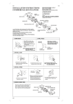
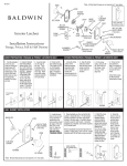
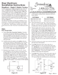
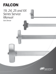
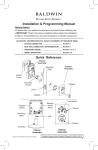
PK 5710_ENG_02BALD108 Tahoe DBLC v4 7/27/11 4:05 PM Page 1
1 Before You Begin
PK.5710
• Remove and discard all materials and screw(s) used for packing your
Premium Entrance Set. Verify that you have all parts pictured on exploded
view section of instructions.
• Check the thickness of the door. This lockset works on doors 13⁄4"
thick only. For doors greater than 13⁄4" up to 21⁄4" thick, contact our
Consumer Help Line at 1-800-566-1986. The conversion kit part
number for this item is 5399.XXX.B; please specify the finish of
your product.
• Follow the step-by-step sequence to ensure proper
operation of your Baldwin lockset.
• If your door is pre-drilled, see handleset installation step 1. If it is not
pre-drilled, see door preparation step 1.
• Important! If you are removing an old lock and replacing it with this
Baldwin lockset, you must install the Baldwin strikeplate provided. Failure
to do so could void your warranty. You may need to plug existing holes left
by the old strikeplate screws with wood dowels and re-drill the pilot holes
for the new strikeplate.
• We recommend spreading cardboard over floor to prevent scratching parts
and marring floor.
• Always wear protective eyewear.
Installation Instructions
ENG L I S H
Note: The illustrations in these instructions depict the outside handle being
installed on the right of the door. For installation of the outside handle on
the left of the door, proceed as if all illustrations were reversed.
Premium Entrance Set
DOUBLE CYLINDER
SECTIONAL TRIMS
Canterbury®
Logan™
Madison®
Handleset Installation
Fasteners
Exploded View
Outside Cylinder
Required Tools
Tailpiece
Keys
Outside Collar
Deadbolt
Set Screw
Inside Cylinder Collar Base
#8 x 3⁄4" Combination Screws
Protective
Eyewear
Phillips
Screwdriver
Flat Head
Screwdriver
Tape
Measure
Electric
Drill
21⁄8" Dia. Face
Bore Hole Saw
1
1
⁄16" Wood
Drill Bit
1" Spade Bit or
1" Hole Saw
(Recommended)
Pencil
Chalk,
Grease Pencil,
or Lipstick
Utility
Knife
Masking Tape
24" Level
Hammer
⁄32" Wood
Drill Bit
Pliers
Needlenose
Pliers
⁄2" Wood
Chisel
⁄8" Wood
Drill Bit
(2) #8-32 x 1⁄4"
Screws
Inside Cylinder Assembly
Outside Handleset Trim
#10-32 x 21⁄4" Flat Head Screws
Post
#8-32 x 1⁄4" Screws
Strikeplate (Deadbolt)
Inside Cylinder Cap
Inside Cylinder Collar
Latch
3" Reinforcing Screws
Spindle
Reinforcing
Strike
#10-32 x 11⁄4" Flat
Head Screws
Spacer
#8 x 3⁄4" Combination Screws
Inside Adapter
#8 x ⁄4"
Combination Screws
3
Dustbox
5
(4) #8 x 3⁄4"
Combination
Screws
Left-Hand
Lever
V Groove
(2) #8 x 3⁄4"
Wood Screws
RightHand Lever
5
Door Frame Template
Helpful Tools
Rose Retainer
Screw Base
Rosette
#8 x 3⁄4" Wood Screws
Strikeplate (Latch)
Dustbox
Tahoe®
Door Hole Template
Strikeplate Installation
Fasteners
Rose Retainer Wrench
#10-32 x 23⁄4" Oval Head Screw
Knob
Set Screw
Allen Wrench
#10-32 x 23⁄4"
Oval Head
Screw
2 Door Preparation (If Needed)
(2) #10-32 x 21⁄4"
Flat Head
Screws
Masking
tape
(2) #8 x 3⁄4"
Combination
Screws
(2) 3"
Reinforcing
Screws
(2) #10-32 x 11⁄4"
Flat Head
Screws
Wood Filler
Beeswax
or Soap
1"
31⁄2"or 37⁄8"
door stop
B
B
A
A
C
C
hole template
low side of bevel
D
E
D
top of door
1
Pull door toward you to
check if it’s level. Observe
contact of door to jam and
make sure it’s level. Adjust if
necessary.
5305
5315
5325
5320
Remember Baldwin
2
(Aerial View) To ensure
proper alignment, only use
hole template on side facing
doorstop.
Helpful Hint: Some doors
have a beveled edge with bevel
facing doorstop.
3
Fold hole template along
door edge with center of
bottom hole (A), the 21⁄8" dia.
hole, 38" from floor. Tape
template to door.
With the completion of your project, remember that Baldwin quality
hardware products are available for all your decorating and remodeling
needs. Matching entrance sets for exterior doors, beautiful bath
accessories, and a complete selection of cabinet and door-enhancing
hardware are all available from your Baldwin retailer.
4
Determine backset, which
is the distance from the edge of
door to center of hole. Use
hole template to mark the
backset center point for your
installation. Locate and mark
positions for (A, B, C, D, and
E) on template. The most
common backset is 23⁄8".
5
Very carefully drill (A, B)
21⁄8" holes into one side of door
face until drill bit starts to
protrude on opposite side.
Important: Drill
perpendicularly (at a 90º
angle) to door.
6
7
Complete drilling holes (A,
B) from opposite side of door.
Very carefully drill (C, D) holes
into door edge exactly at pencil
marks.
31⁄2" deep for a 23⁄8" backset
37⁄8" deep for a 23⁄4" backset
Helpful Hint: Mark edge depth
of drilling with masking tape.
8
Very carefully drill (E) 5⁄16"
hole into door exactly at
pencil mark.
9
Insert latch into hole (D).
Use utility knife to score
chisel guides into door edge.
Make sure score guides are
parallel to door. Repeat for
deadbolt hole (C).
10 Chisel faceplate cavity
5
⁄32" deep.
Helpful Hint: Chisel toward
inside edge of score lines,
removing only a small bit to
avoid wood damage.
To request a product brochure or the name of a retailer near you,
call 1-800-566-1986.
PK.5710
12/11
Congratulations!
3 Handleset Installation
With your purchase of this Premium Entrance Set, you’re among a group
of discerning individuals who know the intrinsic value of selecting the
finest—Baldwin.
slot
Top
Spindle
Align tailpiece with
slot so it’s vertical
Our step-by-step installation instructions will help guide you through your
project quickly and easily.
notch
slot
13⁄4" 2" 21⁄4"
Before you begin your installation, read and understand the installation
instructions and marking templates. If you have any questions, please
do not hesitate to contact our Baldwin Consumer Help Line at
1-800-566-1986. We’re here to help! We thank you for your purchase
and wish you the fullest enjoyment of your Baldwin product.
V groove
on bottom
toward
hinges
top of door
inside
cylinder
outside
cylinder
cylinder
tailpieces
inside
1
Determine your backset,
which is the distance from
the edge of door to center of
hole. Your lockset is shipped
with a 23⁄8" backset (most
common). Adjust for a 23⁄4"
backset door only.
Care and Maintenance
WARNING: Do not attempt to clean your hardware with any type of
abrasive cleaners, solvents, or chemicals. These types of cleaning agents
may mar the finish. A damp cloth is all that is necessary to wipe clean.
Note: Finish Number 102, Oil-Rubbed Bronze, can be cleaned with light
machine oil and wiped with a dry cloth.
2
For a 23⁄4" backset, grasp
body and twist faceplate 180º
until it stops. Angled side of
bolt should face outside.
Follow same procedure for
deadbolt.
Note: See deadbolt orientation
during installation step 4.
3
Insert latch with angled side
of bolt facing outside. Drill 1⁄8"
pilot holes. Secure with #8 x 3⁄4"
combination screws so latch is
flush with door. Repeat for
deadbolt.
Helpful Hint: When
installing wood screws it is
recommended to put beeswax or
soap on screw threads to
improve installation.
inside
4
Note orientation of deadbolt.
Insert deadbolt. Drill 1⁄8" pilot
holes. Secure with #8 x 3⁄4"
combination screws so latch is
flush with door.
inside
5
For both cylinders, carefully
break off tailpiece at required
mark for your door thickness.
6
Extend deadbolt with
flat head screwdriver.
Keeping tailpiece vertical and
toward the right side of hole,
insert outside cylinder through
outside cylinder collar, then
into deadbolt. Hold in place.
Note: Do not insert key.
door edge
inside
7
Keeping tailpiece vertical and
curved toward right side of hole,
insert inside cylinder through
inside cylinder collar base,
aligning slot on top of inside
cylinder with notch on inside
cylinder collar base, into
deadbolt. Secure with two
#10-32 x 21⁄4" flat head screws.
E
8
(Aerial view) Align tailpiece
with slot. Keep tailpiece vertical
and curved toward right side of
hole. Note: Cylinder tailpieces
must meet each other as shown.
9
Align inside cylinder cap
over inside cylinder. Screw on
inside cylinder collar.
inside
inside
Attach outside handleset
trim by inserting the #10-32 x
23⁄4" oval head screw on inside of
door through screw base and the
lower hole (E). Leave screw loose
for adjustment.
Note: Go to door preparation
if you do not have a lower
hole (E).
From inside of door, insert
short end of spindle through the
latch with the V groove angled
down and toward hinges. Position
outside handleset trim so spindle
slides into square hole in
thumbpiece cartridge.
Note: Make certain spindle is
completely inserted up to stops.
inside
inside
10
Measure the thickness of
your door. If door is less than
13⁄4" thick, do not use the
spacer provided. If your door
measures 13⁄4", slide the spacer
onto spindle.
11
12
inside
inside
Position rosette onto inside
adapter. Using rose retainer
wrench, thread the rose retainer
onto the threaded portion of the
adapter.
Slide knob onto spindle
and tighten set screw with Allen
wrench. Knob/lever is secured
when set screw enters V groove in
spindle.
inside
13
Align spindle, latch, and
outside handle. Insert the inside
adapter onto the posts of the
outside handleset trim. Secure
with two #10-32 x 11⁄4" flat head
screws. Tighten all three screws,
including screw for bottom of
handle.
14
15
Baldwin offers a vast array of exceptional solid brass products to elegantly
enhance all areas of the home. Each collection features a wide variety of
beautiful, high-fashion finishes. From door hardware to bath accessories,
Baldwin provides the discriminating decorator with numerous options to accent
and complement the home’s ambience with distinction, taste, and fine detail.
Installation
4 Strikeplate
IMPORTANT! You must install Baldwin strikeplate or your warranty is void.
Consumer Help Line
1-800-566-1986
Troubleshooting Guide
If parts are missing do not return product. Please call Baldwin's Consumer Help Line at 1-800-566-1986 and we will quickly send the parts to you.
Hours: 8 a.m. to 8 p.m. E.S.T - Monday - Friday
10 a.m. to 6 p.m. E.S.T - Saturday
5/32"
Problem
Can’t extend deadbolt unless key is in cylinder. Can’t remove key with deadbolt in
extended position.
Screws are all tight but the hardware is not firmly attached to the door.
Inside knob or lever spins freely and does not retract latch bolt. Deadbolt retracts when
thumbpiece on outside is pushed.
Knob or lever keeps coming off the spindle.
outside
If you have trouble installing your Baldwin product, feel free to call our
toll-free Consumer Help Line.
1/8"
inside
1
Browse through the Baldwin Collection of beautiful locks, bath
accessories and decorative hardware. Compare styles and finishes.
There are thousands of photos and descriptions available to help you
coordinate hardware throughout your home. Create your ideal "wish
list" then visit your Baldwin Retailer or Dealer. Visit
www.baldwinhardware.com today!
www.baldwinhardware.com
©2011 Baldwin Hardware Corporation
841 East Wyomissing Blvd., Reading, PA 19611
If weather stripping is
not installed, you must
install weather stripping
prior to strikeplate
installation. Mark center of
deadbolt with chalk, grease
pencil, or lipstick. Shut door
and lock deadbolt to mark
center point on doorframe.
2
On doorframe, align strike
hole template with center
point. Mark holes for center of
latch bolt and outer corners of
both strikes with pencil.
inside
3
For Deadbolt and
Latch Strikeplates: Mark
drill points 5⁄16" above and
below center points. Bore two
1" holes 11⁄4" deep for both
dustboxes. Score chisel guide
into door frame with utility
knife.
inside
4
For Deadbolt and
Latch Strikeplates: Chisel
out holes for dustboxes. Chisel
out cavity so deadbolt
strikeplate and latch
strikeplate fit flush with
doorframe.
For deadbolt strikeplate,
cavity is 7⁄32" deep.
For latch strikeplate,
cavity is 3⁄32" deep.
inside
5
For Deadbolt
Strikeplate: Using
reinforcing strikeplate as a
template, drill two 5⁄32" pilot
holes for 3" long screws
(outside holes) and two 1⁄8"
pilot holes for #8 x 3⁄4" screws
(inside holes).
inside
6
inside
For Deadbolt
Strikeplate: Insert dustbox
into hole, add reinforcing
strike, and secure with 3"
reinforcing screws (outside
holes) and #8 x 3⁄4" combination
screws (inside holes).
Helpful Hint: When
installing wood screws it is
recommended to put beeswax
or soap on screw threads to
improve installation.
inside
7
For Deadbolt
Strikeplate: Add strikeplate
and secure with #8-32 x 1⁄4"
screws.
inside
8
For Latch Strikeplate:
Using latch strikeplate as a
template, drill two 1⁄8" pilot
holes for the #8 x 3⁄4" screws.
inside
Door is difficult to latch or will not stay closed unless deadbolt is extended.
9
For Latch Strikeplate:
Insert dustbox into hole, add
strikeplate, and secure by
inserting #8 x 3⁄4" wood screws
into pilot holes.
Can’t extend deadbolt from inside or outside with key when door is closed.
Door is already prepared with round hole for latch.
Deadbolt works easily on inside but is difficult to turn and has grinding sound when
turned with key on outside.
Solution
Cylinder is out of time. Remove both cylinders. Extend deadbolt with screwdriver and re-install hardware. Refer to handleset
installation step 6.
Check door thickness. Door must be 13⁄4" thick. Hardware will not install on doors less than 13⁄4" thick.
Spindle is installed backwards. Short side of spindle must face exterior. Long side of the spindle is installed toward inside of house. Refer to
handleset installation step 12.
Ensure that set screw on knob or lever is installed in V groove on spindle and securely tightened with Allen wrench provided. Refer to
handleset installation step 14.
Strikeplate is not aligning with latchbolt. Remove, plug holes with wooden dowels and glue. Adjust and re-install. Condition can also
be caused by weather stripping being installed after hardware is installed. Re-install strike as described at left. Refer to strikeplate
installation step 1.
Open door and try to extend deadbolt. If deadbolt extends easily with door open, deadbolt strike is not aligned with deadbolt. Remove
strike and relocate as necessary. Refer to strikeplate installation step 1.
Replace door or return lockset to place of purchase. Baldwin does not manufacture a round (drive-in) latch at this time.
Improper alignment of outside and inside cylinder or improper door thickness. Use a block of wood to tap cylinder collar so it will
not move more than 1⁄16" in any direction. If this does not correct problem, check deadbolt hole preparation for accuracy. Ensure that
door is 13⁄4" thick. Refer to handleset installation step 6.