1
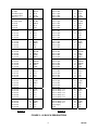
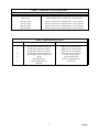
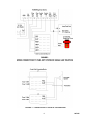
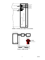
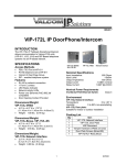
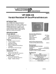
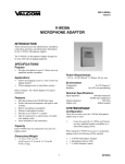
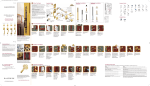
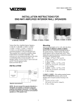
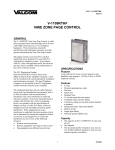
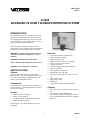
VSP-V-2920
Issue 6
V-2920
ADVANCED 20 ZONE TALKBACK INTERCOM SYSTEM
INTRODUCTION
The V-2920, Advanced 20 Zone Talkback Intercom
System, is a communications system which provides
voice paging with handsfree reply for up to 20 zones.
The V-2920 is for use with any electronic or 1A2 key
system, or PABX loop start trunk port.
These instructions contain the specifications and
information necessary to install, operate, and maintain
the Advanced 20 Zone Talkback Intercom System.
Features
"WARNING: To reduce the risk of fire or electric
shock, do not expose this appliance to rain or
moisture."
•
•
•
•
•
•
•
•
•
•
•
"WARNING: Shock Hazard - Do Not Open."
"AVIS: Risqué de Choc Electrique ne pas Ouvrir."
"PELIGRO: Corriente Electrica - No Abres."
SPECIFICATIONS
Purpose
The V-2920 provides 20 zones of paging with
handsfree reply. The system also provides the ability
for a remote speaker location equipped with a call
button to call the attendant location.
•
•
•
•
Components
The V-2920 system consists of three components: A
V-2920 Control, a V-2990 Ring Down Device, and a
VP-324 Power Supply.
Capacity
•
Access
•
•
•
•
20 zones of handsfree communication
Built-in handsfree amplifier
Background music input
Built-in all call with "meet me" capability
"Ring in" from speaker locations
Calls placed in queue
Override capability from speaker locations
Dial tone (optional)
Alert/ringback tone (optional)
Repeated alert tone (optional)
Auxiliary contact closures for zones 26, 27, 28,
29
Lamp contact closure
Ring contact closure
Inhibit input
Control unit is battery backup compatible
•
•
PABX Loop Start Trunk Port
E-Key C.O. line position
1A2 Key line position equipped with line card
Dedicated single line phone
The capacity of the V-2920 is 20 zones plus all
call.
The V-2920 is a single talkpath unit.
The maximum number of speakers per zone are
two, 45 Ohm speakers and 40 one-way amplified
speakers.
Refer to Figure 1 for a block diagram of a typical
installation.
1
947305
P A B X ,
E L E C T
O R 1 A
S Y S T E
D E D IC
S IN G L
T E L E P
R O
2 K
M
A T
N IC
E Y
O R
E D
E L IN E
H O N E
V -2 9
R IN
D O W
D E V
G
9 0
4 5 O H M
T A L K B A C K
S P E A K E R
V -2 9 2 0
C O N T R O L
U N IT
N
IC E
C A L L B U T T O N
(U P T O
2 0 Z O N E S )
F IG U R E 1
S IM P L IF IE D B L O C K D IA G R A M
O F A
T Y P IC A L IN S T A L L A T IO N
Zone 26 Contact Operates when station 26 is dialed
and the "*" key is pressed.
Zone 27 Contact Operates when station 27 is dialed
and the "*" key is pressed.
Zone 28 Contact Operates when station 28 is dialed
and the "*" key is pressed.
Zone 29 Contact Operates when station 29 is dialed
and the "*" key is pressed.
Dimensions/Weight
•
•
•
•
•
•
Control Unit - 8.55" H x 11.0" W x 2.35" D
(21.72cm H x 27.94cm W x 5.97cm D)
6.7 lbs. (3.04 kg)
Ring Down Device – 8.2”H x 4.55”W x 2.3”D
(20.83cm H x 11.56cm W x 5.84cm D)
1.25 lbs. (.57 kg)
Power Supply – 3.0”H x 2.5”W x 2.0”D
(7.62cm H x 6.35cm W x 5.08cm D)
0.8 lbs. (.36 kg)
Volume Controls
The V-2920 is equipped with 5 volume controls.
Nominal Specifications
•
•
•
•
V-2920 - Control Unit
Input Impedance:
600 Ohms
Input Level:
-10 dBm
Output Impedance:
45 Ohms
Aux/Music Input:
8-600 Ohm low level
•
•
V-2990 - Ring Down Device
Input Impedance:
600 Ohms
Output Voltage:
90 Vac ring generator
•
VP-324 - Power Supply
- Output:
24 Vdc +/- 3 V "B" Battery
(Unfiltered Signal Battery)
•
•
•
•
•
Power Requirements
V-2920 - Control Unit
Voltage:
Power:
The dialing codes are 10 to 29 and 0 for all call.
VP-324 - Power Supply
Input:
105-120 Vac, 60 Hz, 18 watts
Auxiliary Contacts
The V-2920 is equipped with 6 sets of auxiliary
contact closures. They are:
Lamp Contact
Ring Contact
115 Vac
30 Watts
V-2990 - Ring Down Device
Power:
-21.5 to -26.0 Vdc, 200 mA
Numbering Plan
•
Phone to Speaker - Adjusts the transmit volume.
Speaker to Phone - Adjusts the receive volume.
Music 1 adjusts background music for zones
10-19.
Music 2 adjusts background music for zones
20-29.
All Call adjusts the one-way all call level.
Environment
•
•
Operates on loop closure.
Follows ringing cycle 2
seconds "ON", 4 seconds
"OFF".
2
Temperature:
Humidity:
0 to 40 Degrees C
0 to 85% non-precipitating
947305
DESIGN
INSTALLATION
General
Precautionary Designations
The V-2920, Advanced 20 Zone Talkback Intercom
System used with the Valcom talkback speakers,
provides voice paging with handsfree reply for up to
20 zones.
RIS K O F E LE CTRIC S HO CK
The system can be accessed through a C. O. line
position of a key system, loop start trunk port or
single line telephone. Zones are selected by dialing a
two digit number. The user can then page the area
and anyone hearing the page can reply back
handsfree. (By using one-way amplified speakers, a
zone can be one-way).
CA UTIO N: To reduc e the ris k of elec tric s hoc k ,
Do not rem ove c over.
No us er s ervic eable parts ins ide.
Refer s ervic ing to qualified s ervic e pers onnel.
This s y m bol indic ates that dangerous
voltage c ons tituting a ris k of elec tric
s hoc k is pres ent within this unit.
The system can also be accessed from a talkback
speaker location. When a call button at the speaker is
pressed, the dedicated line or trunk port will begin to
ring. A person hearing the incoming ring accesses the
line or trunk. The person at the telephone can then
talk with the person at the speaker location. (Valcom
doorplate speakers are normally used in these
applications).
This s y m bol indic ates that there are
im portant operating and m aintenanc e
ins truc tions in the literature ac c om pany ing
this unit.
Cabling
Two 25 pair cables with female connectors should be
run from the Control Unit (V-2920) to each of the
connecting blocks. The cables should be terminated
on the connecting blocks in standard color code
color. An opening is provided at the bottom of the
Control Unit to allow exit of the cables. A "punch
out" slot is designated at the top of this opening to be
"punched out" to allow additional cabling exit space,
if required.
When the system is in use and another call is placed
from a speaker location, the person on the telephone
will hear 3 short tones and the call will be placed in
queue. If the # key is pressed, the telephone user will
be connected to the new calling location. The system
will remember the order that calls come in and will
switch to the next call in queue when the # is pressed.
A person can override a call in progress by pressing
the call button four (4) times within a four (4) second
time period. The person at the telephone will be
connected to the zone that originated the override and
the call in progress will be placed in queue.
Mounting
The V-2920 System was designed to be wall or table
mounted. When wall mounting the V-2920 System,
secure the units to wall studs or a suitable brace. (A
plywood backboard 2' square and at least 1/2" thick
attached to wall studs would be considered a suitable
brace). Make certain the units are not mounted near
heat sources or strong magnetic fields. Ascertain
control and terminal strip accessibility.
Zones 26 to 29 can be in the normal queue or be
programmed to have a lower priority than the rest of
the zones. In the lower priority mode, the zones can
be used for door locations or other areas not requiring
immediate response from the attendant. These zones
will be bumped from their place in queue and put at
the end of the line if another zone calls in. There are
also contact closures associated with zone 26-29.
The contact closures can be operated by pressing the
"*" key on the telephone key pad after the zone has
been called. These contacts can be used to operate
electric strike plates on doors.
Six 3/4" cross-tip round head wood screws are
included for mounting the V-2920 and V-2990.
Fasten two of these screws at the appropriate location
on the mounting surface, allowing the screwheads to
protrude 1/8" to 1/4". Place the chassis of the
Control Unit (V-2920) onto the screwheads at the
mounting slots. Position two screws through the
remaining mounting slots and fasten. Complete
mounting the Control Unit by tightening all screws.
Using the two screws remaining, mount the Ring
Down Device (V-2990) in a similar manner.
The V-2920 provides a background music input, and
is designed to automatically cut off the music during a
page. If background music is to be installed, a low
level music source such as the V-2952 FM Tuner will
be required.
3
947305
Connections
___ 1.
___ 2.
___ 3.
___ 4.
___ 5.
Page and Music Level Set-Up
Mount two 66B type punchdown blocks on
the backboard near the Control Unit
(V-2920) and Ring Down Device (V-2990)
and label the blocks per Figure 2.
Connect the control unit Tip and Ring (J1 W/BL, BL/W) to screw terminals 3 and 4 of
the ring down device.
Connect the control unit Ring contact
closure pair (J1 - W/GN, GN/W) to screw
terminals 5 and 6 of the ring down device.
Connect screw terminals 1 and 2 of the ring
down device to the appropriate C. O. port of
the telephone system.
Connect screw terminals 7 and 8 of the ring
unit to the VP-324 power supply "-" and "+"
terminals respectively.
The control unit has volume controls for the
following functions:
• Speaker to Phone
• Phone to Speaker
• All Call
• Music One - Zones 10-19
• Music Two - Zones 20-29
Refer to Figure 5 for user control locations.
Control Set-Up:
1. Set up Talkback Controls
(a) The phone to speaker should be at a normal
listening level.
(b) Speaker to Phone Level:
This is the most critical level; set the volume
at the lowest practical level. (It is better to
set it too low than too high).
(c) Individual volume controls of any one-way
amplified speakers can then be adjusted for
normal listening level.
Refer to Figure 3 for Wiring Designations.
Door Plate Connections
The following connections are for zone 10 of the
system. Other zones will connect in the same manner
to their appropriate terminals.
__ 1.
__ 2.
__ 3.
__ 4.
2. All Call Level
The all call level should be set to produce
the same audio level as the phone to speaker
control.
Connect Tip of the door plate speaker to
W/BL of block J2.
Connect Ring of the door plate speaker to
BL/W of block J2.
Connect one side of the door plate switch to
R/BL of block J1.
Connect the other side of the door plate
switch to BL/R of block J1.
3. Background Music Levels
There are two volume controls provided for
background music adjustments: Zones
10-19 and 20-29.
NOTE: Two pair twisted station cable is
recommended for connections between the control
unit and the door plate speakers. (Refer to Figure 4).
It is important that these two background music
controls be used to adjust music levels in the system.
Adjust these controls after all other volume controls
have been set.
Music Connections
Auxiliary Contacts
The output of a low level music source connects to
W/OR,OR/W on block J1 of the control unit.
NOTE: Do not connect the output of a high
power amplifier to this input.
Refer to Table 1 for description of the various contact
closures.
Setting of Program Dip Switches
AC Power
Refer to Table 2 for dip switch functions.
Connect AC power cord after all required
connections have been accomplished.
4
947305
Ring Input
Tip Input
Aux/Music Input
Aux/Music Input
Ring C. C.
Ring C. C.
HF Inhibit Input
Not Used
Not Used
Not Used
Sta 10 SW
Sta 10 Gnd
Sta 11 SW
Sta 11 Gnd
Sta 12 SW
Sta 12 Gnd
Sta 13 SW
Sta 13 Gnd
Sta 14 SW
Sta 14 Gnd
Sta 15 SW
Sta 15 Gnd
Sta 16 SW
Sta 16 Gnd
Sta 17 SW
Sta 17 Gnd
Sta 18 SW
Sta 18 Gnd
Sta 19 SW
Sta 19 Gnd
Sta 20 SW
Sta 20 Gnd
Sta 21 SW
Sta 21 Gnd
Sta 22 SW
Sta 22 Gnd
Sta 23 SW
Sta 23 Gnd
Sta 24 SW
Sta 24 Gnd
Sta 25 SW
Sta 25 Gnd
Sta 26 SW
Sta 26 Gnd
Sta 27 SW
Sta 27 Gnd
Sta 28 SW
Sta 28 Gnd
Sta 29 SW
Sta 29 Gnd
26
1
27
2
28
3
29
4
30
5
31
6
32
7
33
8
34
9
35
10
36
11
37
12
38
13
39
14
40
15
41
16
42
17
43
18
44
19
45
20
46
21
47
22
48
23
49
24
50
25
Zone 10 Spk
Zone 10 Ret
Zone 11 Spk
Zone 11 Ret
Zone 12 Spk
Zone 12 Ret
Zone 13 Spk
Zone 13 Ret
Zone 14 Spk
Zone 14 Ret
Zone 15 Spk
Zone 15 Ret
Zone 16 Spk
Zone 16 Ret
Zone 17 Spk
Zone 17 Ret
Zone 18 Spk
Zone 18 Ret
Zone 19 Spk
Zone 19 Ret
Zone 20 Spk
Zone 20 Ret
Zone 21 Spk
Zone 21 Ret
Zone 22 Spk
Zone 22 Ret
Zone 23 Spk
Zone 23 Ret
Zone 24 Spk
Zone 24 Ret
Zone 25 Spk
Zone 25 Ret
Zone 26 Spk
Zone 26 Ret
Zone 27 Spk
Zone 27 Ret
Zone 28 Spk
Zone 28 Ret
Zone 29 Spk
Zone 29 Ret
Zone 26 Relay Com
Zone 26 Relay N.O.
Zone 27 Relay Com
Zone 27 Relay N.O.
Zone 28 Relay Com
Zone 28 Relay N.O.
Zone 29 Relay Com
Zone 29 Relay N.O.
Lamp Supply
Lamp
W/BL
BL/W
W/O
O/W
W/GR
GR/W
W/BR
BR/W
W/S
S/W
R/BL
BL/R
R/O
O/R
R/G
G/R
R/BR
BR/R
R/S
S/R
BK/BL
BL/BK
BK/O
O/BK
BK/G
G/BK
BK/BR
BR/BK
BK/S
S/BK
Y/BL
BL/Y
Y/O
O/Y
Y/G
G/Y
Y/BR
BR/Y
Y/S
S/Y
V/BL
BL/V
V/O
O/V
V/G
G/V
V/BR
BR/V
V/S
S/V
BLOCK J1
26
1
27
2
28
3
29
4
30
5
31
6
32
7
33
8
34
9
35
10
36
11
37
12
38
13
39
14
40
15
41
16
42
17
43
18
44
19
45
20
46
21
47
22
48
23
49
24
50
25
W/BL
BL/W
W/O
O/W
W/GR
GR/W
W/BR
BR/W
W/S
S/W
R/BL
BL/R
R/O
O/R
R/G
G/R
R/BR
BR/R
R/S
S/R
BK/BL
BL/BK
BK/O
O/BK
BK/G
G/BK
BK/BR
BR/BK
BK/S
S/BK
Y/BL
BL/Y
Y/O
O/Y
Y/G
G/Y
Y/BR
BR/Y
Y/S
S/Y
V/BL
BL/V
V/O
O/V
V/G
G/V
V/BR
BR/V
V/S
S/V
BLOCK J2
FIGURE 2 - 66 BLOCK DESIGNATIONS
5
947305
There are also contact closures associated with zones
26 to 29. The contact closures can be operated by
pressing the "*" key on the telephone key pad after
the zone has been called. These contacts can be used
to operate electric strikeplates on doors.
OPERATION
General
Originating a Page
When the attendant accesses the intercom and dials
the access code, dial tone is returned. The attendant
can then select an area to be paged by dialing a two
digit number (10 to 29). A tone is heard in the
handset and at the speaker location. The attendant
can then page the area and anyone hearing the page
can reply back handsfree to the speaker.
All Call with Meet Me
When the attendant accesses the All Call feature to
locate a specific individual, the desired person can
then respond from any speaker by pressing the
push-button at the speaker four (4) times. When this
is done, all other speakers are cut off and this
individual speaker becomes talkback to allow
two-way conversation.
Receiving a Call From a Door Box
When the button is pressed on the speaker, the
dedicated line or trunk port will begin to ring. A tone
is also heard at the speaker location. Hearing the
incoming ring, the attendant accesses the trunk or
C.O. line. The person at the speaker location can
then talk handsfree to the attendant.
Inhibit Option
If a single line telephone is desired for "meet me
answer," a single line "A" lead control telephone and
a 5.1K ohm resistor will be required. The T & R of
the telephone connects to the W/BL pair, the "A1"
lead connects to GND (BL/R), the "A" lead has the
5.1K ohm resistor placed in series, and the resistor
terminates on inhibit (W/BR).
Auxiliary Contacts
The control unit provides a contact closure that
follows the ringing cycle. Contact closures are
provided for electric strike plate operation for zones
26 to 29. A lamp contact closure is provided.
TECHNICAL ASSISTANCE
Troubleshooting Chart
For additional information on the various contact
closures refer to Table 1.
Table 3 identifies some possible problems with
solutions.
Queue Operation
When the system is in use and another call is placed
from a speaker location, the person on the telephone
will hear 3 short tones and the call will be placed in
queue. If the # key is pressed, the telephone user will
be connected to the new calling location. The system
will remember the order that calls come in and will
switch to the next call in queue when the # key is
pressed.
Factory Assistance
When trouble is reported, verify the unit is turned on
and there are no broken connections leading to this
system.
Assistance in troubleshooting is available from the
factory. When calling, you should have a VOM and
a telephone test set available and be calling from the
job site. Call (540) 427-3900 and ask for Technical
Support, or call (540) 427-6000 for Valcom 24-hour
Automated Support or visit our website at
http://www.valcom.com.
Queue Override
A person can override a call in progress by pressing
the call button four (4) times within a four (4) second
time period. The person at the telephone will be
connected to the zone that originated the override and
the call in progress will be placed in queue.
Valcom equipment is not field repairable. Valcom
maintains service facilities in Roanoke, VA. Should
repairs be necessary, attach a tag to the unit clearly
stating your company name, address, phone number,
contact person, and the nature of the problem. Send
the unit to:
Valcom, Inc.
Repair and Return Dept.
5614 Hollins Road
Roanoke, VA 24019-5056
Special Programming Zones 26 to 29
Zones 26 to 29 can be in the normal queue or be
programmed to have a lower priority than the rest of
the zones. In the lower priority mode the zones can
be used for door locations or other areas not requiring
immediate response from the attendant. These zones
will be bumped from their place in queue and put at
the end of the line if another zone calls in.
6
947305
TABLE 1: AUXILIARY CONTACT OPERATION
Contact
Operation
Lamp Contact
Ring Contact
Zone 26 Contact
Zone 27 Contact
Zone 28 Contact
Zone 29 Contact
Operates on loop closure.
Follows ringing cycle 2 seconds "ON", 4 seconds "OFF".
Operates when zone 26 is dialed and the "*" key is pressed.
Operates when zone 27 is dialed and the "*" key is pressed.
Operates when zone 28 is dialed and the "*" key is pressed.
Operates when zone 29 is dialed and the "*" key is pressed.
TABLE 2: DIPSWITCH FUNCTIONS
SWITCH #
"OFF" POSITION
"ON" POSITION
1
2
3
4
5
6
7
8
Normal queue sequence on zone 26.
Normal queue sequence on zone 27.
Normal queue sequence on zone 28.
Normal queue sequence on zone 29.
Queue signal output to telephone and
speaker.
Repeated alert tone.
Alert tone/Ringback tone.
Dial tone.
Bump zone 26 to end of queue.
Bump zone 27 to end of queue.
Bump zone 28 to end of queue.
Bump zone 29 to end of queue.
No queue signal output.
No repeated alert tone.
No alert tone/Ringback tone.
No dial tone.
7
947305
8
947305
All Call Volume
Music Zones
10-19 Volume
Phone to Spk
Music Zones
20-29 Volume
Feature Switches
Spk to Phone
J1
J2
FIGURE 5 - CONTROL AND CONNECTOR LOCATIONS
J1 Connecting Block
BL/W
W/BL
T
R
V-2990
Tel Sys. C.O..
Line position
or loop start
trunk port
W/BR
BL/R
Dedicated
"Meet Me"
Answer Telephone
Inhibit
Ground
T R A A1
5.1k ohm
FIGURE 6 - INHIBIT OPTION
9
947305
TABLE 3: TROUBLESHOOTING CHART
PROBLEM
CORRECTIVE ACTION
1. No system operation.
1a. Verify AC voltage is present at the receptacle.
1b. Check the fuse located on the bottom of the unit.
If blown replace with a .5amp, 250 Vac fuse.
1c. Verify that 25 pair cable connectors are completely
plugged into circuit board connectors.
1d. Refer to Figure 2 and verify all connections.
2. No paging at speaker.
3. Paging at speaker but no reply from speaker.
2a. Check door plate speaker connections.
2b. Refer to Figure 5 and adjust Phone to Speaker
volume.
4. No system ringing when the doorplate button
is pressed.
3.
Refer to Figure 5 and adjust Speaker to Phone
volume.
5. Background music is not heard at speakers.
4.
Refer to the Connection Sections and verify all
connections.
5.
Refer to Music Connection and Setup sections.
6.
Refer to Page and Music Level Setup Section.
7.
Refer to Table 2 for dipswitch settings.
6. No all call.
7. No dial tone.
VALCOM LIMITED WARRANTY
Valcom, Inc. warrants its products to be free from defects in materials and workmanship under conditions of normal use and service
for a period of one year from the date of shipment. The obligation under this warranty shall be limited to the replacement, repair or
refund of any such defective device within the warranty period, provided that:
1.
2.
3.
4.
5.
inspection by Valcom, Inc. indicates the validity of the claim,
the defect is not the result of damage, misuse, or negligence after the original shipment.
the product has not been altered in any way or repaired by others and that factory sealed units are unopened (A service
charge plus parts and labor will be applied to units defaced or physically damaged),
freight charges for the return of products to Valcom are prepaid,
all units ‘out of warranty’ are subject to a service charge. The service charge will cover minor repairs (Major repairs will be
subject to additional charges for parts and labor).
This warranty is in lieu of and excludes all other warranties, expressed or implied, and in no event shall Valcom, Inc. be
liable for any anticipated profits, consequential damages, loss of time or other losses incurred by the buyer in connection
with the purchase, operation, or use of the product.
This warranty specifically excludes damage incurred in shipment. In the event a product is received in damaged condition, the
carrier should be notified immediately. Claims for such damage should be filed with the carrier involved in accordance with the
F.O.B. point.
Headquarters:
Valcom, Inc.
1111 Industry Avenue
Roanoke, VA 24013
Phone: (540) 427-3900
FAX: (540) 427-3517
In Canada
CMX Corporation
35 Van Kirk Drive #11 and 12
Brampton, Ontario L7A1A5
Phone: (905) 456-1072
FAX: (905) 456-2269
10
947305