1
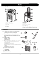
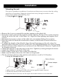
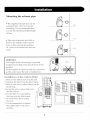
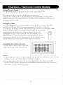
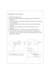
Parts Front Back 5. Air Filter 6. Air Inlet 7. Exhaust Air Outlet 8. Cord Hanger 9. Water Stopper (Rubber Plug Inside) 1. Control Panel 2. Cooling Air Outlet 3. Handle 4. Castors Accessories 10. Adaptor - for insertion over the hose and into the back of the air conditioner. 11. Round Connector - to be used between hose and window kit or between hose and wall. 1 2. Exhaust Hose Length: 14”-60” Diameter: 4.75” 13. plastic Slider kit-for filling the open window space and with a hole for connection to thexhaust hose. Dimension:7”x24.5 ”x0.75 ” plastic Slider kit - for filling the open window space. Dimension:7”x24.5 ”x0.75 ” 14. Cap for Round Connector 15. Drain tube 16. Carbon filter 17. Remote Control 4 14 Installation Mounting the unit This unit is a portable air conditioner. It can be moved from room to room so that the cooling can follow you anywhere. Fitting the exhaust hose is easy, through a window or wall. Please refer to either of the following ways: 1. Using the P lastic slider kit FIG.5 Remove the 4 scre ws around the circular opening on the plastic kit. Insert the round connector through the circular opening, the lip of the round connector should be on the flat side of the slider kit. Align the screw openings and replace the 4 sc rews. Determine how many se ctions of the slider kit your window/sliding door requires. Place the sli der kit inside the window/door frame, with flat side of round connector facing out. To adjust the height of the slider kit: align the small openings o n the side, when the desired height is rea ched, inse rt a small scre w (not supplied) through one of the o pening. Extend one e nd of the exhaust hose a nd insert it into the Round Connector. Tighten hose by turning clockwise. Attach the Adapter to the other end of the hose. Tighten by turning Adapter clockwise. Attach the Adapter to the back of the unit. Slide window / patio door close a gainst the slider kit. Make sure the exhau st hose ha s no kinks or sharp bends. The be st distance betwee n the machine and window or wall is 31-39 inche s. 2. Using the Through the Wall Wall or Window Outward adaptor FIG.6 FIG.7 • Make a hole (5" in diameter) in the wall to fit the supplied round connector. • Fit the hose directly to the round connector. • When the hole is not in use, use the cap for the round connector to cover the hole. 5