1
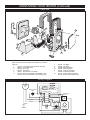
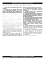
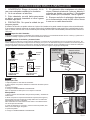
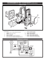
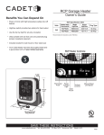
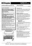
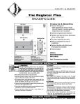
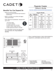
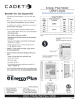
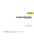
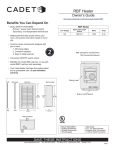
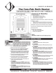
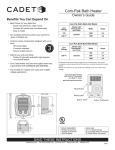
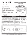
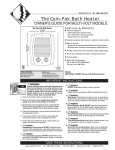
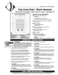
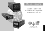
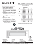
The Hot One Garage Heater
Owner’s Guide
Benefits You Can Depend On
• Peace of mind with high temperature safety shut off
feature
• HI/LOW switch provides two options for heat output
• Use the fan by itself for air-only circulation
• Ultra-portable with six-foot cord and polarized plug
(proper receptacle required)
Information is also available on our website:
http://www.cadetheat.com/products/garage-heaters/RCP
The Hot One Specification Table
Volts
240
Model with
thermostat
Watts
high/low
Amps
high/low
Plug Type
RCP502S
5000/3333
20.8/13.9
30 Amp
RCP402S
4000/2667
16.7/11.1
20 Amp
The Hot One is recommended for elevations under 7500 feet.
• Includes bracket for wall mount or floor stand use
• Your Cadet heater has been thoroughly tested and
is guaranteed with a limited 5 year warranty
The Hot One Heater Controls:
8-1/4"
20.9 cm
Thermostat
Knob
17-1/2"
44.5 cm
Power
ON/AUTO
Indicator
Controls
Light
Watts
HI/LOW
Manual Reset
Limit Button
8-1
20.9 /4"
cm
15-3/
4
40 cm"
20 Amp 240 Volt
Plug Pictured
SAVE THESE INSTRUCTIONS
cadetheat.com
Tel: 855.CADET.US
PO Box 1675 Vancouver, WA
98668-1675
Page 1
IMPORTANT INSTRUCTIONS
When using electrical appliances, basic precautions should always be followed to reduce the risk of fire,
electric shock, and injury to persons, including the following:
1. Read all instructions before using this heater.
2. This heater is hot when in use. To avoid
burns, do not let bare skin touch hot surfaces. If
provided, use handles when moving this heater.
Keep combustible materials, such as furniture,
pillows, bedding, papers, clothes and curtains at
least 3 feet (.9 m) from the front of the heater and
keep them away from the sides and rear.
3. Extreme caution is necessary when any heater
is used by or near children or invalids and whenever the heater is left operating and unattended.
4. Always unplug heater when not in use.
5. Do not operate any heater with a damaged
cord or plug, or after the heater malfunctions,
has been dropped or damaged in any manner.
Return heater to authorized service facility for
examination, electrical or mechanical adjustment
or repair.
6. Do not use outdoors.
7. This heater is not intended for use in bathrooms,
laundry areas and similar indoor locations. Never
locate heater where it may fall into a bathtub or
other water container.
8. Do not run cord under carpeting. Do not cover
cord with throw rugs, runners, or similar coverings.
Arrange cord away from traffic area and where it
will not be tripped over.
9. To disconnect heater, turn controls to off, then
remove plug from receptacle.
10. Connect to properly grounded receptacles
only.
11. Do not insert or allow foreign objects to enter
any ventilation or exhaust opening as this may
cause an electric shock or fire, or damage the
heater.
12. To prevent a possible fire, do not block air
intakes or exhaust in any manner. Do not use on
soft surfaces, like a bed, where openings may
become blocked.
13. A heater has hot and arcing or sparking parts
inside. Do not use it in areas where gasoline,
paint, or flammable vapors or liquids are used or
stored.
14. Use this heater only as described in this
manual. Any other use not recommended by the
manufacturer may cause fire, electrical shock, or
injury to persons.
15. Always plug heater directly into a wall
receptacle. Never use with an extension cord or
relocatable power tap (receptacle/power strip).
16. CAUTION: Do not operate without stand
attached.
17. Save these instructions.
SAVE THESE INSTRUCTIONS
Page 2
cadetheat.com
Tel: 855.CADET.US
PO Box 1675 Vancouver, WA
98668-1675
INSTALLATION INSTRUCTIONS
1. WARNING: Risk of fire. Do not use as a
residential or household heater.
2. Do not use outdoors.
3. This heater is not intended for use in bathrooms,
laundry areas, and similar indoor locations.
4. CAUTION: Do not operate without stand
attached.
5. Heater must be kept clear of all obstructions:
3 foot minimum clearance from front, 6 inch
minimum clearance from back and top, and 12
inch minimum clearance from sides. See Figure
3.
6. Always plug the heater directly into a 240 volt
wall receptacle. Never use an extension cord.
The Hot One may sit on a floor surface or be mounted to the wall using the universal stand provided. If mounted on the
wall, maintain 6 inch minimum clearance from the top of the unit to the ceiling. The Hot One is not recommended for
ceiling mount. Recommended for elevations under 7500 feet.
STEP 1 Heater Inspection
Thoroughly inspect your heater for any shipping or handling damage and remove any paper or packaging material around the heater.
STEP 2 Grounding Plug and Receptacle Requirements
This heater is for use with 240 volts. The cord has a 20 amp or 30 amp plug as shown in Figure 1. No adapter is available for these
blade configurations, and none should be used. The Hot One requires a 240 volt grounded receptacle. When properly installed, it
provides a ground connection through the cord to the heater to protect the operator from electric shock. Do not use an extension cord,
power strip or any kind of adapter.
RCP502S - 30 Amp
Plug Configuration
6” min. clearance
from back and
top of heater
RCP402S - 20 Amp
12” min. clearance
from sides of heater
Plug Configuration
3’ min. clearance er
from front of heat
Receptacle Configuration
NEMA #6-30R
Figure 2
Receptacle Configuration
NEMA #6-20R
Figure 1
STEP 3 Mounting
Floor Standing
1. Loosen knobs on each side of the heater.
2. Rotate stand to desired position at bottom of heater (See Figure 2).
3. Tighten knobs.
4. Proceed to OPERATING INSTRUCTIONS.
Note: The heater must be operated with the stand attached to the heater
Wall Mount
1. Remove stand from heater by removing knobs and washers from both
sides.
2. Mount stand in desired position on wall (See Figure 3). The wall and
mounting hardware must be of adequate strength to support the heater.
Note: A 240 volt receptacle must be within six feet of the heater.
3. Install heater on stand and reassemble knobs, washers, stand and bracket
according to Figure 4.
4. Tighten knobs.
5. Proceed to OPERATING INSTRUCTIONS.
Figure 3
BRACKET
STAND
STEEL
WASHER
RUBBER
WASHER
KNOB
6” desde la parte
posterior y superior
del calentador
Figure 4
Distancia mínima
Page 3
de 12” desde los
costados del calentador
OPERATING INSTRUCTIONS
1. The heater must be properly installed before
it is used. Be sure the plug fits tightly into the
receptacle. The red light indicates the unit is
plugged in.
2. Do not operate without the stand attached.
3. Do not use breaker panel or wall thermostat to
control heater.
4. Always unplug heater when not in use.
5. Clean heater at least every six months or as
required. See “MAINTAINING YOUR HEATER”.
6. CAUTION: Risk of electrical shock. Do not
open. No user-serviceable parts inside. Any
other service not detailed in this owner’s guide
should be performed by an authorized service
representative.
How to Operate Your Heater
Select the “LOW” wattage setting. If your desired temperature is not reached, select the “HI” setting. NOTE: The temperature of the air
coming from the front of the heater will be approximately 40˚F warmer than the room temperature, in the “HI” setting. With extremely
cold environments, air from the heater may not feel hot. As the heater continues to operate, the heater air and surrounding air temperature will continue to increase.
Fan running continuously with intermittent heat
Fan running
Fan cycling with heat
continuously
The room temperature is controlled by a line voltage thermo- Determined by the thermostat setting
1. Turn the ON/AUTO switch to the “ON” position and with no heat
stat built-in to the heater.
1. Turn the
1. Turn ON/AUTO switch to the “AUTO” position and turn the turn the thermostat knob fully clockwise.
ON/AUTO
thermostat knob fully clockwise.
2. When the room reaches your comfort level, turn
the thermostat knob counterclockwise until the heater switch to the
2. When the room reaches your comfort level, turn the ther“ON” position.
mostat knob counterclockwise until the heater turns off. The turns off. The heater will automatically cycle around
this preset temperature, however the fan will run con- 2. Turn the
heat and the fan will automatically cycle around this preset
stantly.
thermostat
temperature.
knob just
3. To reduce the room temperature, turn the knob
3. To reduce the room temperature, turn the knob counterabove the
counterclockwise. To increase the room temperature,
clockwise. To increase the room temperature, turn the knob
“OFF” position.
turn the knob clockwise.
clockwise.
Resetting the Manual Reset Limit Control
About the Manual Reset Temperature Limit Control
The heater is protected by a high temperature manual reset control, designed to open the heater circuit and
stop the electrical current flow when excessive operating temperatures are detected.
Resetting the Manual Reset Temperature Limit Control
If the manual reset limit control has opened the heater circuit due to excessive operating temperatures, the
heater will not work or may blow cold air until the limit reset button is pressed. After allowing the unit to cool for
at least 10 minutes and resolving the problem causing the limit to trip (typically the heater is blocked or needs
cleaning); use a narrow object such as a ball-point pen to access the reset button through the lower-right hole
marked “RESET”. Press FIRMLY. If the manual reset continues to trip, see Troubleshooting Chart.
Manual Reset Limit Button
Warranty
For more effective and safer operation and to prolong the life of the
heater, read the Owner’s Guide and follow the maintenance instructions.
Failure to properly maintain the heater will void any warranty and may
cause the heater to function improperly. Warranties are non transferable
and apply to original consumer only. Warranty terms are set out below.
LIMITED FIVE-YEAR WARRANTY: Cadet will repair or replace any Hot
One (RCP) heater found to be defective within five years after the date of
purchase.
These warranties do not apply:
1. Damage occurs to the product through improper installation or incorrect supply voltage;
2. Damage occurs to the product through improper maintenance, misuse,
abuse, accident, or alteration;
3. The product is serviced by anyone other than Cadet;
4. If the date of manufacture of the product cannot be determined;
5. If the product is damaged during shipping through no fault of Cadet.
6. The use of unauthorized accessories or unauthorized components
constitutes an alteration and voids all warranties. Refer to Cadet website
or call customer service at 855.CADET.US for list of authorized accessories and components.
7. CADET’S WARRANTY IS LIMITED TO REPAIR OR REPLACEMENT
AS SET OUT HEREIN. CADET SHALL NOT BE LIABLE FOR DAMAGES
SUCH AS PROPERTY DAMAGE OR FOR CONSEQUENTIAL DAMAGES AND/OR INCIDENTAL EXPENSES RESULTING FROM BREACH
OF THESE WRITTEN WARRANTIES OR ANY EXPRESS OR IMPLIED
WARRANTY.
Page 4
8. IN THE EVENT CADET ELECTS TO REPLACE ANY PART OF YOUR
CADET PRODUCT, THE REPLACEMENT PARTS ARE SUBJECT TO
THE SAME WARRANTIES AS THE PRODUCT. THE INSTALLATION
OF REPLACEMENT PARTS DOES NOT MODIFY OR EXTEND THE
UNDERLYING WARRANTIES. REPLACEMENT OR REPAIR OF ANY
CADET PRODUCT OR PART DOES NOT CREATE ANY NEW WARRANTIES.
9. These warranties give you specific legal rights, and you may also
have other rights which vary from state to state. Cadet neither assumes,
nor authorizes anyone to assume for it, any other obligation or liability in
connection with its products other than as set out herein.
If you believe your Cadet product is defective, please contact Cadet
Manufacturing Co. at 855.CADET.US, during the warranty period, for
instructions on how to have the repair or replacement processed. Warranty claims made after the warranty period has expired will be denied.
Products returned without authorization will be refused.
Parts and Service
Visit cadetheat.com/parts-service for information on where to obtain parts
and service.
Reduce-Reuse-Recycle
This product is made primarily of recyclable materials. You
can reduce your carbon footprint by recycling this product at
the end of its useful life. Contact your local recycling support
center for further recycling instructions.
MAINTAINING YOUR HEATER
Maintenance As Needed, or every six months minimum.
WARNING: Any other service not detailed in this Owner’s Guide should be performed by an
authorized service representative.
1. Allow the heater to cool, then disconnect the power cord from
power supply. To disconnect heater, turn control to “OFF”, then
remove plug from receptacle.
2. Remove front diffuser grill by removing the four screws (one
from each corner).
3. Wash grill with hot soapy water and dry, or use air compressor
to blow debris from grill louvers.
4. While holding fan (to avoid damage or bending), use an air compressor, hair dryer or vacuum on blow cycle to blow debris through
the outer cabinet louvers and finned elements.
5. Vacuum or blow air inside fan area without touching the elements.
6. Carefully wipe off the fan blade without damaging or bending it.
7. Replace diffuser grill and secure with screws.
Troubleshooting Chart
*CONSULT LOCAL ELECTRICAL CODES TO DETERMINE WHAT WORK MUST BE PERFORMED BY QUALIFIED
ELECTRICAL SERVICE PERSONNEL. ALWAYS UNPLUG HEATER BEFORE SERVICING.
Symptom
Problem
Solution
The plug does not 1. Heater is 240 volt requiring a 20 amp
fit receptacle.
or 30 amp 240 volt receptacle (see
Figure 1 in “INSTALLATION INSTRUCTIONS”).
1. DO NOT alter cord. Install the proper 240 volt receptacle (see Figure 1 in “INSTALLATION INSTRUCTIONS”).*
Heater does not
operate.
1. Heater is or has been blocked.
2. Thermostat set too low.
3. Circuit breaker not turned on.
4. Loose plug connection.
5. Defective manual reset limit.
1. Remove obstruction. Push manual reset button found in front lower
panel.
2. Turn knob clockwise until a click sound is heard.
3. Turn circuit breaker on.
4. Check plug connection.
5. Replace manual reset limit.*
Elements heat,
fan does not
operate.
1. Jammed fan blade.
2. Defective motor.
1. Remove obstruction.
2. Replace fan motor.*
Heater fan
operates,
but does not
discharge warm
air.
1. Manual reset limit tripped.
2. ON/AUTO switch is “ON” and thermostat setting is below actual temperature.
3. Defective heater elements.
4. Wire loose from elements.
5. Temperature rise on heater is 40°F.
1. Allow heater to cool, then push reset.
2. Increase the thermostat setting; turn ON/AUTO switch to “AUTO”.
Heater does not
shut off.
1. Heat loss from area is greater than
heater capacity.
2. Defective thermostat.
3. ON/AUTO switch in “ON” position.
1. Close doors or windows. Provide additional insulation and/or
heaters.
2. Replace thermostat.*
3. Change ON/AUTO switch to “AUTO” setting.
Heater
discharges
smoke.
1. Dust, dirt, and lint accumulated inside
the heater.
1. Clean heater. (See “MAINTAINING YOUR HEATER” section for
instructions). Blow dirt accumulation off heater with compressed air
(air compressor recommended).
2. Remove obstruction.
Manual reset limit
trips repeatedly.
1. Overheating.
2. Jammed blade.
2. Overheating at shutdown.
3. Overheating from excessive dust or
dirt particles.
4. Overheating due to elevation of
location.
3. Replace elements.*
4. Check and correct loose wire.
5. Close doors or windows. Provide additional insulation and/or heaters. Wait for room to warm up.
1. Check all clearance requirements. 6" minimum clearance required
between top of heater and ceiling. Heater is not recommended for
ceiling mount.
2. Discontinue use of breaker to control heater.
3. Clean heater (See “MAINTAINING YOUR HEATER” section for
instructions).
4. Location elevation exceeds recommended 7500 feet.
Page 5
MAINTAINING YOUR HEATER (continued)
Parts List
6
8
7
1
11
5
3
4
10
12
2
9
Figure 4
Note: Only the items listed below are available for purchase.
Parts List
1. 410102 Front Diffuser Grill Assembly with clips
2.
040019 Thermostat Knob
3.
050524 Pilot Light
4.
051226Thermostat
5.
050327 Temperature Limit Switch
6.
401723 Element, RCP402S 1333/1000W (3 req.)
401726 Element, RCP502S 1667/1332W (3 req.)
7.
8.
9.
10.
11.
12.
001601
051424
400202
040023
051901
051903
051707
051708
Fan Blade
Fan Motor
Mounting Stand
Mounting Knob
Cordset, RCP402S
Cordset, RCP502S
Rocker Switch (HI/LOW)
Rocker Switch (ON/AUTO)
Wiring Diagram
ELEMENTS
CORD
SET
MANUAL RESET
LIMIT
MULTI WATT HI/LOW SWITCH
TERMINAL BLOCK
FAN ON/AUTO
SWITCH
BLACK
WHITE
GREEN
GROUND
Page 6
PILOT
LIGHT
FAN MOTOR
THERMOSTAT
DOUBLE POLE
©2015 Cadet
Printed in USA
Rev 06/15
#720086
El Calentador The Hot One
Guía Para el Propietario
Beneficios En Las Que Puede
Confiar
• Tranquilidad y seguridad gracias a la característica
de corte automático por alta temperatura
• El interruptor HI/LOW ofrece dos opciones para la
generación de calor
También puede encontrar información en nuestro sitio web:
http://www.cadetheat.com/products/garage-heaters/RCP
The Hot One Tabla de Especificaciones
Voltios
Modelo con
Termostato
Vatios
alta / baja
Amps
alta / baja
Tipo de
Enchufe
RCP502S
5000/3333
20.8/13.9
30 Amp
RCP402S
4000/2667
16.7/11.1
20 Amp
240
The Hot One se recomienda para elevaciones inferiores a 7500 pies.
• Use el ventilador por sí solo para la circulación
exclusiva de aire
• Ultraportátil con cable de seis pies y enchufe polarizado (se requiere el tomacorriente correcto)
• Incluye ménsula para montaje mural o uso en
soporte de piso
Controles del calentador The Hot One
• El calentador Cadet se ha probado completamente
y cuenta con el respaldo de una garantía limitada
de 5 años
8-1/4"
20.9 cm
Perilla del
Termostato
Luz
indicadora de
Potencia
Controles
ON/AUTO
Botón de límite
de Reglaje
Manual
Vatios
HI/LOW
17-1/2"
44.5 cm
8-1
20.9 /4"
cm
15-3/
4
40 cm"
Enchufe de 240 Voltios
Representado
CONSERVE ESTAS INSTRUCCIONES
cadetheat.com
Tel: 855.CADET.US
PO Box 1675 Vancouver, WA
98668-1675
Página 7
INSTRUCCIONES IMPORTANTES
Al utilizar artefactos eléctricos, siempre se deben adoptar precauciones básicas para reducir el riesgo
de incendios, electrocución y lesiones personales, incluyendo lo siguiente:
1. Lea todas las instrucciones antes de usar este
calentador.
2. Este calentador se calienta cuando está
en uso. Para evitar quemaduras, no lo toque
con su piel descubierta. Use las manijas, si las
hubiera, al mover este calentador. Mantenga los
materiales combustibles tales como muebles,
cojines, camas, papeles, ropas y cortinas a una
distancia de por lo menos 3 pies (9 m) de la parte
delantera, trasera y costados del calentador.
3. Tenga mucho cuidado cuando use el calentador
en o cerca de niños o de personas inválidas, y
cada vez que lo deje funcionando y sin vigilancia.
4. Siempre desenchufe el calentador cuando no
lo esté usando.
5. No opere el calentador si el cable o enchufe
están dañados, si se ha caído o sufrido algún tipo
de daño. Devuelva el calentador a un centro de
servicio autorizado para que lo revisen, le realicen
ajustes eléctricos o mecánicos, o lo reparen.
6. No lo use a la intemperie.
7. Este calentador no está hecho para usarse
en baños, zonas de lavandería ni otros lugares
similares bajo techo. Nunca coloque el calentador
donde pueda caer en una bañera o algún otro
recipiente con agua.
8. No tienda el cable bajo las alfombras. No
cubra el cable con alfombras, tapetes ni objetos
similares. Disponga el cable lejos de zonas de
tránsito, donde no produzca riesgo de tropiezo.
9. Para desconectar el calentador, ponga el
control en “OFF” y luego quite el enchufe del
tomacorriente.
10. Conecte la unidad sólo a tomacorrientes
con una buena puesta a tierra.
11. No introduzca ni permita que ingresen objetos
en las aberturas de la ventilación o escape, ya
que ello puede causar electrocución o incendio, o
bien dañar el calentador.
12. Para de aire ni el escape de manera alguna.
No lo use en superficies blandas como una cama,
donde las aberturas se puedan obstruir.
13. Todo calentador contiene piezas que se
calientan y pueden producir arcos voltaicos o
chispas. No lo use en áreas donde se utilice o
almacene gasolina, pintura, o vapores o líquidos
inflamables.
14. Use este calentador sólo como se describe en
este manual. Todo otro uso no recomendado por
el fabricante puede causar incendios, descargas
eléctricas o lesiones personales.
15. Siempre enchufe el calentador directamente
en un tomacorriente mural. Nunca lo use con
un cable de extensión ni con una toma de
alimentación reubicable (tomacorriente/regleta).
16. PRECAUCIÓN: No opere la unidad sin que
tenga su soporte.
17. Conserve estas instrucciones.
CONSERVE ESTAS INSTRUCCIONES
Página 8
cadetheat.com
Tel: 855.CADET.US
PO Box 1675 Vancouver, WA
98668-1675
3’ min. clearance er
from front of heat
INSTRUCCIONES PARA LA INSTALACIÓN
1. ADVERTENCIA: Riesgo de incendio. No lo
use como calentador residencial o doméstico.
2. No lo use afuera o al aire libre.
3. Este calentador no está hecho para usarse
en baños, zonas de lavandería ni otros lugares
similares bajo techo.
4. PRECAUCIÓN: No opere la unidad sin que
tenga su soporte.
5. El calentador debe mantenerse sin obstrucciones: Distancia mínima de 3 pies por delante, 6
pulgadas por detrás y por encima, y 12 pulgadas
como mínimo por los costados. Vea la Figura 3.
6. Siempre enchufe el calentador directamente
en un tomacorriente mural de 240 voltios. Nunca
lo use con un cable de extensión.
El modelo The Hot One se puede colocar en el piso o bien instalar en la pared usando el soporte universal suministrado.
Si se monta en la pared, mantenga un espacio mínimo de 6 pulgadas desde la parte superior de la unidad hasta el cielo
raso. El modelo The Hot One no se recomienda para montaje en cielo raso. Recomendado para elevaciones inferiores a
7500 pies.
PASO 1 Inspeccion del Calentador
Inspeccionar cuidadosamente su calentador para verificar que el mismo no ha sido dañado durante el envío o manejo y quitar todo el
material de embalaje o papeles que se encuentren alrededor del calentador.
PASO 2 Requisitos de enchufes y tomacorrientes
Éste calentador se debe usar con 240 voltios. El cable tiene un enchufe de 20 o 30 amperios, tal como se aprecia en la Figura 1. No
existen adaptadores para estas configuraciones de clavijas, por lo que no se debe utilizar ninguno. El modelo The Hot One requiere un
tomacorriente de 240 voltios con puesta a tierra. Cuando se instala correctamente, pone el calentador a tierra a través del cable para
proteger al operador contra electrocuciones. No use cable de extensión, regleta ni ningún tipo de adaptador.
RCP502S - 30 Amp
RCP402S - 20 Amp
Conexión
a Tierra
Conexión
a Tierra
Configuraciones
del Enchufe
6” desde la parte
posterior y superior
del calentador
Distancia mínima
de 12” desde los
costados del calentador
Configuraciones
del Enchufe
Conexión
a Tierra
Configuraciones del
Toma de Corriente
NEMA #6-30R
Distancia mínima
de 3 pies delante
del calentador
Conexión
a Tierra
Configuraciones del
Toma de Corriente
NEMA #6-20R
Figura 2
Figura 1
PASO 3 Montaje
Soporte para Piso
1. Afloje las perillas en cada lado del calentador.
2. Gire el soporte a la posición deseada en la base del calentador (Vea la
Figura 2).
3. Apriete las perillas.
4. Prosiga con OPERACIÓN DEL CALENTADOR.
Nota: El calentador se debe operar con el soporte conectado.
Montaje Mural
1. Retire el soporte del calentador extrayendo las presillas y arandelas de
ambos lados.
2. Monte el soporte en la posición deseada de la pared (Vea la Figura 3).
Tanto la pared como los herrajes de montaje deben tener la resistencia
adecuada para soportar el calentador.
Nota: Debe haber un tomacorriente de 240 voltios a una distancia máxima de seis pies del calentador.
3. Instale el calentador en el soporte y vuelva a montar las perillas, arandelas y la escuadra según la Figura 4.
4. Apriete las perillas.
5. Prosiga con OPERACIÓN DEL CALENTADOR.
Figura 3
ABRAZADERA
BASE
ARANDELA
DE ACERO
ARANDELA
DE GOMA
PERILLA
Figura 4
Página 9
OPERACIÓN DEL CALENTADOR
1. El calentador debe instalarse correctamente
antes de usarlo. El enchufe debe calzar
exactamente en el tomacorriente. La luz roja
indica que la unidad está encendida.
2. No opere la unidad sin que tenga su soporte.
3. No utilice el panel de cortacircuitos, ni el
termostato mural para controlar el calentador.
4. Siempre desenchufe el calentador cuando no
lo esté usando.
5. Limpie el calentador por lo menos cada
seis meses o según sea necesario. Vea
“MANTENIMIENTO DEL CALENTADOR”.
6. PRECAUCIÓN: Riesgo de electrocución. No
abrir. No contiene piezas que pueda reparar
el usuario. Todo otro servicio no detallado en
esta Guía del propietario lo debe efectuar un
representante de servicio autorizado.
Cómo hacer funcionar el calentador
Seleccione el ajuste de vatiaje “LOW”. Si no alcanza la temperatura que desea, seleccione el ajuste “HI”. NOTA: La temperatura del
aire procedente de la frontal del calentador sera aproximadamente 40˚F mas caliente que la temperatura ambiente en el ajuste “HI”. En
entornos extremadamente fríos, el aire del calentador puede no parecer caliente. A medida que el calentador continúa funcionando, el
aire y la temperatura circundante continuará aumentando.
Ventilador funcionando continuamente con calor
Ventilador
Ciclos del ventilador con calor
intermitente
funcionando
La temperatura ambiente es controlada por un termocontinuaDeterminado por el ajuste del termostato
stato de voltaje de línea incorporado en el calentador.
mente sin
1. Ponga el interruptor ON/AUTO en la posición de “ON”
1. Ponga el interruptor ON/AUTO en la posición de
calor
y luego gire la perilla del termostato completamente en
“AUTOMÁTICO” y luego gire la perilla del termostato
el sentido de las manecillas del reloj.
1. Ponga el
completamente en el sentido de las manecillas del reloj.
interruptor
2. Cuando la habitación haya alcanzado un nivel cómo2. Cuando la habitación haya alcanzado un nivel
ON/AUTO en
do, gire la perilla del termostato en sentido contrario a
cómodo, gire la perilla del termostato en sentido
la posición de
las manecillas del reloj hasta que el calentador se apacontrario a las manecillas del reloj hasta que el
“ON”.
gue. El calentador comenzará a encenderse y apagarse
calentador se apague. El calor y el ventilador se
automáticamente según esta temperatura prefijada,
2. Gire la
encenderán y apagarán automáticamente según esta
pero el ventilador funcionará constantemente.
perilla del
temperatura preestablecida.
termostato
3. Para reducir la temperatura del ambiente, gire la pe3. Para reducir la temperatura del ambiente, gire la
justo sobre la
rilla en sentido contrario a las manecillas del reloj. Para
perilla en sentido contrario a las manecillas del reloj.
posición de
aumentar la temperatura del ambiente, gire la perilla en
Para aumentar la temperatura del ambiente, gire la
“APAGADO”.
el sentido de las manecillas del reloj.
perilla en sentido contrario a las manecillas del reloj.
Cómo restablecer el control de límite de reglaje manual
Acerca del Control de límite de Temperatura de Reglaje Manual
El calentador está protegido mediante un interruptor de reglaje manual de alta temperatura, diseñado para
abrir el circuito del calentador y detener el flujo de corriente eléctrica cuando se detectan temperaturas de
funcionamiento excesivas.
Cómo Restablecer el Control de Límite de Reglaje Manual
Si el control de límite de reglaje manual ha abierto el circuito del calentador debido a temperaturas de funcionamiento excesivas, el calentador no funcionará o bien puede soplar aire frío hasta que se oprima el botón de
reglaje del límite. Después de dejar que la unidad se enfríe durante unos 10 minutos y resolver el problema
que causa que se disyunte el interruptor de límite (generalmente el calentador está bloqueado o necesita
limpieza), utilice un objeto puntiagudo como un bolígrafo para acceder al botón de reglaje a través del orificio
inferior derecho marcado “RESET”. Oprima el botón FIRMEMENTE y asegúrese de escuchar y sentir un chasquido indicando que se ha restablecido. Si el reglaje manual continúa disyuntándose, revise el espacio libre
alrededor del calentador y cerciórese de que cumpla con las distancias recomendadas.
Garantía
Para lograr una operación más eficaz y segura y prolongar la vida útil del
calentador, lea la Guía del propietario y siga las instrucciones de mantenimiento. Si no le da el mantenimiento adecuado al calentador invalidará la garantía y puede hacer que el aparato funcione incorrectamente. Las garantías
no son transferibles y rigen sólo para el comprador original. Los términos de la
garantía se indican a continuación.
GARANTÍA LIMITADA DE CINCO AÑOS: Cadet reparará o reemplazará todo
calentador The Hot One (RCP) que se determine esté averiado en un plazo
de cinco años a partir de la fecha de compra.
Estas garantías no son pertinentes para:
1. Daños que sufra el producto por instalación o voltaje de suministro incorrectos;
2. Daños que sufra el producto por mantenimiento incorrecto, uso indebido,
abuso, accidente o alteraciones;
3. Servicio que se le haya dado al producto por parte de personas o entidades
ajenas a Cadet.
4. Casos en que no se pueda determinar la fecha de fabricación del producto;
5. Casos en que el producto resulte dañado durante el embarque por causas
ajenas a Cadet.
6. El uso de accesorios o componentes no autorizados constituye una alteración e invalida las garantías. Consulte el sitio web de Cadet o bien llame
al servicio al cliente al 855.CADET.US para ver una lista de los accesorios y
componentes autorizados.
7. LA GARANTÍA DE CADET SE LIMITA A LA REPARACIÓN O REEMPLAZO,
TAL COMO SE ESTABLECE EN ESTE DOCUMENTO. CADET NO SE HARÁ
RESPONSABLE POR DAÑOS A LA PROPIEDAD O DAÑOS CONSECUENTES, COMO TAMPOCO POR GASTOS ACCIDENTALES DEBIDO AL
INCUMPLIMIENTO DE ESTAS GARANTÍAS ESCRITAS O DE CUALQUIER
GARANTÍA EXPRESA O IMPLÍCITA.
Página 10
Botón de límite de
Reglaje Manual
8. EN CASO DE QUE CADET DECIDA REEMPLAZAR ALGUNA PIEZA DEL
PRODUCTO CADET, LOS REPUESTOS SE REGIRÁN POR LAS MISMAS
GARANTÍAS DEL PRODUCTO. LA INSTALACIÓN O REEMPLAZO DE LOS
REPUESTOS NO MODIFICA NI PROLONGA LAS GARANTÍAS VIGENTES.
EL REEMPLAZO O REPARACIÓN DE TODO PRODUCTO O PIEZA CADET
NO ORIGINA NINGÚN TIPO DE NUEVA GARANTÍA.
9. Estas garantías le otorgan derechos legales específicos y es posible que
usted tenga otros derechos que varíen de un estado a otro. Cadet no asume
ni autoriza a nadie que lo haga en su nombre, ninguna otra obligación o
responsabilidad en relación con sus productos que no sean las que se establecen en este documento.
Si durante el período de garantía usted considera que su producto Cadet presenta defectos, comuníquese con Cadet Manufacturing Co. llamando al 855.
CADET.US para obtener instrucciones sobre cómo tramitar la reparación o el
reemplazo del producto. Los reclamos de garantía presentados después de la
finalización del período no serán acogidos. Los productos que se devuelvan
sin autorización serán rechazados.
Repuestos y Servicio
En cadetheat.com/parts-service encontrará información sobre dónde obtener
repuestos y servicio.
Reduzca-Reutilice-Recicle
Este producto está hecho principalmente de materiales reciclables. Puede reducir la cantidad de carbono que contribuye al
medio ambiente reciclando este producto al término de su vida
útil. Comuníquese con su centro local de reciclaje para obtener
mayores instrucciones al respecto.
MANTENIMIENTO DEL CALENTADOR
Mantenimiento Según sea necesario, o cada seis meses como mínimo.
ADVERTENCIA: Toda otra labor no detallada en esta Guía para el propietario la debe efectuar un
representante de servicio autorizado.
1. Deje que el calentador se enfríe, y luego desconecte el cable
eléctrico de la fuente de alimentación. Para desconectarlo, ponga
el control en “OFF” y luego quite el enchufe del tomacorriente.
2. Quite la rejilla difusora delantera extrayendo los 4 tornillos (1
de cada esquina).
3. Lave la rejilla con agua caliente con detergente y séquela, o
bien use un compresor de aire para soplar la suciedad de las
persianas.
4. Mientras sujeta el ventilador (para evitar que se dañe o tuerza), utilice un compresor de aire, un secador de cabello o una
aspiradora en el ciclo de soplado para quitar la suciedad en las
persianas del armario externo y los elementos con aletas (sin
tocarlos, ya que éstos tienen superficies afiladas).
5. Aspire o sople aire dentro de la zona del ventilador sin tocar
los elementos.
6. Limpie cuidadosamente el aspa con un paño sin dañarla ni
torcerla.
7. Vuelva a instalar la rejilla difusora y fíjela con los tornillos.
Tabla de resolución de problemas
*CONSULTE LOS CÓDIGOS ELÉCTRICOS LOCALES PARA DETERMINAR QUÉ TRABAJOS DEBEN SER
REALIZADOS POR PERSONAL DE SERVICIO ELÉCTRICO CALIFICADO. SIEMPRE DESENCHUFE EL
CALENTADOR ANTES DE DARLE SERVICIO.
Síntoma
El enchufe no
calza en el tomacorriente.
Problema
1. El calentador es de 240 voltios por lo
que requiere un tomacorriente también
de 240 voltios y de 20 ó 30 amperios (ver
Figura 1 en INSTRUCCIONES PARA LA
INSTALACIÓN ).
Solución
1. NO altere el cable. Instale un tomacorriente correcto de 240
voltios (consulte la Figura 1 en INSTRUCCIONES PARA LA INSTALACIÓN).*
El calentador no
funciona.
1. El calentador está o ha estado bloqueado.
2. El termostato se ha graduado muy bajo.
3. El cortacircuito no está encendido.
4. Conexión del enchufe suelta.
5. Limitador de reglaje manual averiado.
1. Retire la obstrucción. Presione el botón de reglaje manual que se
encuentra en el panel delantero inferior.
2. Gire la perilla en el sentido de las manecillas del reloj hasta que
se escuche un chasquido.
3. Encienda el cortacircuito.
4. Verifique la conexión del enchufe.
5. Reemplace el limitador de reglaje manual.*
Los elementos
calientan, pero
el ventilador no
funciona.
1. Aspa del ventilador atascada.
2. Motor defectuoso.
1. Retire la obstrucción.
2. Reemplace el motor del ventilador.*
El ventilador
del calentador
funciona pero
no envía aire
caliente.
1. Se disyuntó el limitador de reglaje
manual.
2. Interruptor ON/AUTO del ventilador está
encendido en “ON” y el ajuste del termostato está bajo la temperatura real.
3. Elementos calentadores defectuosos.
4. Alambre suelto en los elementos.
5. El aumento de temperatura en el calentador es de 40°F.
1. Deje que el calentador se enfríe y luego presione el reglaje.
El calentador no
se apaga.
1. La pérdida de calor de la zona es superior a la capacidad del calentador.
2. Termostato defectuoso.
3. El interruptor ON/AUTO del ventilador
está encendido en “ON”.
1. Cierre puertas y ventanas. Ponga más aislamiento o más
calentadores.
2. Reemplace el termostato.*
3. Cambie el interruptor ON/AUTO del ventilador al ajuste “AUTO”.
El calentador
emite humo.
1. Se han acumulado polvo, suciedad y
pelusas dentro del calentador.
1. Limpie el calentador (vea las instrucciones en la sección “MANTENIMIENTO DEL CALENTADOR”). Limpie la acumulación de
suciedad del calentador con aire comprimido (se recomienda usar
un compresor de aire).
2. Retire la obstrucción.
El límitador de
reglaje manual se
disyunta reiteradamente.
1. Sobrecalentamiento.
2. Aspa del ventilador atascada.
2. Sobrecalentamiento al apagar el
aparato.
3. Sobrecalentamiento por exceso de
polvo o partículas de suciedad.
4. Sobrecalentamiento debido a la elevación del lugar de instalación.
2. Aumente el ajuste del termostato; coloque el interruptor ON/
AUTO del ventilador en “AUTO”.
3. Reemplace los elementos.*
4. Revise y corrija el alambre suelto.
5. Cierre puertas y ventanas. Ponga más aislamiento o más calentadores. Espere que la habitación se entibie.
1. Verifique todos los requisitos de espaciado. Se requiere un
espaciado mínimo de 6 pulg. entre la parte superior del calentador
y el cielo raso. No se recomienda el uso de este calentador para
montaje en cielo raso.
2. Deje de usar el cortacircuito para controlar el calentador.
3. Limpie el calentador (vea las instrucciones en la sección “MANTENIMIENTO DEL CALENTADOR”).
4. La elevación del lugar de instalación sobrepasa los 7500 pies
recomendados.
Página 11
MANTENIMIENTO DEL CALENTADOR (continuación)
Lista de Piezas
6
8
7
1
11
5
3
4
10
12
2
9
Nota: Sólo los elementos antedichos están disponibles para la venta.
Lista de Piezas
1. 410102 Conjunto de Rejilla Difusora Frontal con Presillas
2.
040019 Perilla del Termostato
3.
050524 Luz de Piloto
4.
051226Termostato
5.
050327 Interruptor de límite de Temperatura
6.
401723 Elemento, RCP402S 1333/1000W (se req. 3)
401726 Elemento, RCP502S 1667/1332W (se req. 3)
Figura 4
7.
8.
9.
10.
11.
12.
001601
051424
400202
040023
051901
051903
051707
051708
Ventilador de Aspas
Motor del Ventilador
Soporte de Montaje
Perilla de Montaje
Juego de Cables, RCP402S
Juego de Cables, RCP502S
Interruptor Basculante (HI/LOW)
Interruptor Basculante (ON/AUTO)
Diagramas de cableado
ELEMENTOS
JUEGO DE
CABLES
LÍMITE DE
REGLAJE MANUAL
INTERRUPTOR HI/LOW
DE MULTIVATAJE
BLOQUE DE TERMINAL
INTERRUPTOR
ON/AUTO DEL
VENTILADOR
NEGRO
BLANCO
VERDE
CONEXIÓN
A TIERRA
LUZ
TERMOSTATO
DOBLE POLO
MOTOR DEL
VENTILADOR
Página 12
©2015 Cadet
Impreso en EE UU
Rev 06/15
#720086