1
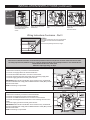
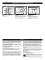
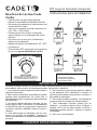
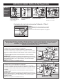
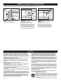
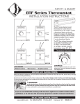
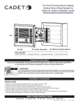
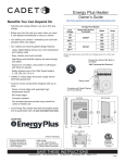
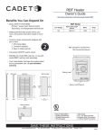
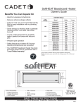
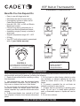
BTF Built-In Thermostat Kit
Installation Instructions
Benefits You Can Depend On
• Easy to use with large twist dial
• Eliminates the need for extra wiring
• Conveniently mounts to either end of
Cadet Electric Baseboard
• Use with 120-, 208-, or 240-volt Electric
Baseboard models
• Choose from white or almond color to
match your Electric Baseboard heater
• Available in single (2 wires) or double (4
wires) pole
• Setpoint temperature range: 45º - 80ºF
• 25 Amp
• Your BTF built-in thermostat is guaranteed
with a 1 year limited warranty
BTF1
BTF2
BTF1TP
BTF2TP
er
ol
War
m
er
Co
Temperature Set Position
TOOLS REQUIRED
CONTROLS
• Phillips Screwdriver
• Wire Connectors
• Straight Screwdriver
Turn knob counter-clockwise for cooler
room temperature. Turn knob clockwise
for warmer room temperature.
IMPORTANT
When using electrical appliances, basic precautions should always be followed to reduce the risk of fire,
electric shock, and injury to persons, including the following:
1. Read all instructions before installing or using
5. Do not insert or allow foreign objects to enter
this thermostat.
any ventilation or exhaust opening as this may
cause an electric shock or fire, or damage the
2. High temperatures may be generated under
heater.
certain abnormal conditions. Do not partially or
fully cover or obstruct the front of this heater.
6. To prevent a possible fire, do not block air
intakes or exhaust in any manner.
3. Do not operate any heater after it malfunctions.
Disconnect power at service panel and have
7. A heater has hot and arcing or sparking parts
heater inspected by a qualified electrician before
inside. Do not use it in areas where gasoline,
reusing.
paint, or flammable vapors or liquids are used or
stored.
4. To disconnect heater, turn controls to off, and
turn off power to heater circuit at main disconnect 8. Do not use outdoors.
panel.
SAVE THESE INSTRUCTIONS
cadetheat.com
Tel: 360-693-2505
PO Box 1675 Vancouver, WA
98668-1675
Page 1
INSTALLATION INSTRUCTIONS
1. All electrical work and materials must comply
with the National Electric Code (NEC), the Occupational Safety and Health Act (OSHA), and all
state and local codes.
2. Use copper conductors only.
3. Turn off power to heater circuit at main disconnect panel.
4. Connect grounding lead to grounding screw
provided.
Wiring Instructions - Part 1
GROUND
SUPPLY
GROUND
SCREW
STEP 1
Turn the electrical power off at
the circuit breaker or fuse box.
STEP 5
STEP 2
Remove the junction box cover
at the end of the baseboard you
wish to wire.
STEP 3
Connect the supply grounding
wire to the green grounding
screw provided.
Refer to the instructions in Part 2 that correspond to your thermostat application.
GROUND
SCREW
STEP 4
Disconnect one factory connector
on the side you have open,
leaving two loose heater wires.
IMPORTANT: If wiring on the
left side, disconnect ONLY
ONE factory connector!
Wiring Instructions - Part 2
BTF1
240/208
Volt
Application
GROUND
SCREW
A. Connect a hot supply wire to the red
thermostat wire.
GROUND
SCREW
B. Connect the black thermostat wire to
one of the heater wires.
GROUND
SCREW
C. Connect the remaining hot supply
wire to the remaining heater wire.
Proceed to Part 3.
BTF1
120 Volt
Application
GROUND
SCREW
A. Connect the hot supply wire to the
red thermostat wire.
GROUND
SCREW
B. Connect the black thermostat wire to
one of the heater wires.
GROUND
SCREW
C. Connect the neutral supply wire to
the remaining heater wire.
Proceed to Part 3.
BTF2
240/208
Volt
Application
GROUND
SCREW
GROUND
SCREW
A. Connect the black thermostat wires
to the loose heater wires.
Page 2
B. Connect the hot supply wires to the
red thermostat wires.
Proceed to Part 3.
INSTALLATION INSTRUCTIONS (continued)
BTF2
120 Volt
Application
RED
A. Connect the red
thermostat wire labeled
L2 to the black thermostat
wire labeled OFF as
shown.
GROUND
SCREW
GROUND
SCREW
GROUND
SCREW
B. Connect the neutral
supply wire to one of the
heater wires.
C. Connect the supply hot wire
D. Connect the remaining black
to the remaining red thermostat
wire.
thermostat wire to the remaining
heater wire.
Proceed to Part 3.
Wiring Instructions Conclusion - Part 3
STEP 6
Carefully tuck all wires into wiring compartment
and attach the thermostat to the baseboard
heater.
Proceed to Operating Instructions, Page 4.
MULTIPLE HEATER WIRING - OPTIONAL
More than one baseboard heater can be wired in parallel on same circuit (be sure to check national and local codes
for safety requirements). Additional wire is required. Important: When wiring multiple heaters to one thermostat, the
baseboards must be in the same room.
Maximum amperage rating: 25 amps.
BTF1
1. Disconnect one factory connector on each baseboard.
2. Connect one supply lead to the red thermostat wire.
3. Connect black thermostat wire to one wire on each heater.
4. Connect remaining wire from each heater to the remaining supply lead.
5. Connect supply ground wire to both ground screws.
IMPORTANT: Wires shown in illustration are for reference only. All electrical
work and materials must comply with the National Electric Code (NEC) and all
state and local codes.
NOTE: Field wiring is not provided.
FIELD WIRING
FIELD
WIRING
NOT
PROVIDED
GROUND
SCREW
GROUND
SCREW
FIELD WIRING
BTF2
1. Disconnect one factory connector on each baseboard.
2. Connect one supply wire to each red thermostat wire.
3. Connect one black thermostat wire to one wire from each heater.
4. Connect remaining black thermostat wire to the remaining wire from each
heater.
5. Connect supply ground wire to both ground screws.
IMPORTANT: Wires shown in illustration are for reference only. All electrical
work and materials must comply with the National Electric Code (NEC) and all
state and local codes.
NOTE: Field wiring is not provided.
FIELD WIRING
NOT PROVIDED
FIELD WIRING
NOT PROVIDED
GROUND
SCREW
GROUND
SCREW
FIELD WIRING
NOT PROVIDED
Page 3
OPERATING YOUR THERMOSTAT
The heater and thermostat must be properly installed before they are used.
STEP 7
Turn the power back on at the circuit
breaker or fuse box.
STEP 8A
Turn the thermostat knob fully clockwise.
When the room reaches comfort level, turn
the knob counterclockwise until a slight
click is heard. The heater will now cycle
around this preset temperature.
STEP 8B
Tamper Proof Models
Remove plastic plug and adjust the
thermostat shaft to desired setting using a
screwdriver. Replace the plastic plug. The
heater will now cycle around this preset
temperature.
Warranty
For more effective and safer operation and to prolong the life of
the heater, read the Owner’s Guide and follow the maintenance
instructions. Failure to properly maintain the heater will void any
warranty and may cause the heater to function improperly. Warranties are non transferable and apply to original consumer only.
Warranty terms are set out below.
LIMITED ONE-YEAR WARRANTY: Cadet will repair or replace
any Baseboard (BTF) thermostat found to be defective within one
year after the date of purchase.
These warranties do not apply:
1. Damage occurs to the product through improper installation or
incorrect supply voltage;
2. Damage occurs to the product through improper maintenance,
misuse, abuse, accident, or alteration;
3. The product is serviced by anyone other than Cadet;
4. If the date of manufacture of the product cannot be determined;
5. If the product is damaged during shipping through no fault of
Cadet.
6. CADET’S WARRANTY IS LIMITED TO REPAIR OR REPLACEMENT AS SET OUT HEREIN. CADET SHALL NOT BE
LIABLE FOR DAMAGES SUCH AS PROPERTY DAMAGE OR
FOR CONSEQUENTIAL DAMAGES AND/OR INCIDENTAL EXPENSES RESULTING FROM BREACH OF THESE WRITTEN
WARRANTIES OR ANY EXPRESS OR IMPLIED WARRANTY.
Page 4
7. IN THE EVENT CADET ELECTS TO REPLACE ANY PART
OF YOUR CADET PRODUCT, THE REPLACEMENT PARTS
ARE SUBJECT TO THE SAME WARRANTIES AS THE PRODUCT. THE INSTALLATION OF REPLACEMENT PARTS DOES
NOT MODIFY OR EXTEND THE UNDERLYING WARRANTIES.
REPLACEMENT OR REPAIR OF ANY CADET PRODUCT OR
PART DOES NOT CREATE ANY NEW WARRANTIES.
8. These warranties give you specific legal rights, and you may
also have other rights which vary from state to state. Cadet neither assumes, nor authorizes anyone to assume for it, any other
obligation or liability in connection with its products other than as
set out herein.
If you believe your Cadet product is defective, please contact
Cadet Manufacturing Co. at 360-693-2505, during the warranty
period, for instructions on how to have the repair or replacement
processed. Warranty claims made after the warranty period has
expired will be denied. Products returned without authorization
will be refused.
Parts and Service
Visit cadetheat.com/parts-service for information on where to
obtain parts and service.
Reduce-Reuse-Recycle
This product is made primarily of recyclable materials.
You can reduce your carbon footprint by recycling this
product at the end of its useful life. Contact your local
recycling support center for further recycling instructions.
©2014 Cadet
Printed in USA
Rev 09/14
#720107
BTF Juego de Termostato Incorporado
Beneficios En Las Que Puede
Confiar
Instrucciones para la Instalación
• Fácil de usar con gran perilla giratoria
• Elimina la necesidad de cableado adicional
• Se monta cómodamente en cada extremo del
zócalo eléctrico Cadet
• Use con los modelos de zócalo eléctricos de
120-, 208-, o 240-voltios
• Escoja entre el color blanco o almendra
para combinar con su calentador de zócalo
eléctrico
• Se ofrece con un solo polo (2 alambres) o
doble polo (4 alambres)
• Margen de fijación de temperatura: 45º - 80ºF
• 25 Amperios
• El termostato BTF incorporado está garantizado por una garantía limitada de un año
BTF1
BTF2
BTF1TP
BTF2TP
c
os
alor
Má
s
ca
lor
Me
n
Fijar Posición
HERRAMIENTAS NECESARIAS
CONTROLES
Gire la perilla en sentido contrario a
las manecillas del reloj para reducir la
temperatura ambiente. Gírela en el
sentido opuesto para aumentarla.
• Destornillador Phillips
• Conectores de Alambres
• Destornillador Plano
IMPORTANTE
Al utilizar artefactos eléctricos, siempre se deben adoptar precauciones básicas para reducir el riesgo
de incendios, electrocución y lesiones personales, incluyendo lo siguiente:
1. Lea todas las instrucciones antes de instalar o
5. No introduzca ni permita que ingresen objetos
usar este termostato.
en las aberturas de la ventilación o escape, ya
que ello puede causar electrocución o incendio, o
2. Bajo ciertas condiciones anormales se pueden
generar altas temperaturas. No cubra total ni bien dañar el calentador.
parcialmente la tapa, ni obstruya la parte delantera
6. Para evitar posibles incendios, no bloquee las
del calentador.
tomas de aire ni el escape de manera alguna.
3. No opere ningún calentador después de que
7. Todo calentador contiene piezas que se
tenga alguna falla. Desconecte la alimentación
calientan y pueden producir arcos voltaicos o
en el panel de servicio y haga que lo inspeccione
chispas. No lo use en áreas donde se utilice o
un técnico eléctrico calificado antes de volver a
almacene gasolina, pintura, o vapores o líquidos
utilizarlo.
inflamables.
4. Para desconectar el calentador, gire los con8. No lo use a la intemperie.
troles a la posición de apagado, y apague el
circuito del calentador en el panel de desconexión
principal.
CONSERVE ESTAS INSTRUCCIONES
cadetheat.com
Tel: 360-693-2505
PO Box 1675 Vancouver, WA
98668-1675
Página 5
INSTRUCCIONES PARA LA INSTALACIÓN (continuación)
1. Todo trabajo y materiales eléctricos debe cumplir con el Código Eléctrico Nacional (“NEC”, por
sus siglas en inglés), con la Ley de Seguridad y
Salud Ocupacional (“OSHA”, por sus siglas en
inglés) y con todos los códigos estatales y locales.
2. Use sólo conductores de cobre.
3. Apague la energía del circuito del calentador
en el panel de desconexión principal.
4. Conecte el conductor a tierra al tornillo de
puesta a tierra suministrado.
Instrucciones Para el Cableado - Parte 1
Puesta a tierra
del suministro
Tornillo de
puesta a tierra
Tornillo de
puesta a tierra
PASO 1
Desconecte la electricidad en
el cortacircuito o en la caja de
fusibles.
PASO 2
Retire la cubierta de la caja de
empalmes en el extremo del
zócalo que desea cablear.
PASO 3
PASO 4
Conecte el alambre de puesta a
tierra del suministro al cable en
espiral verde de tierra
proporcionado.
Desenchufe un conector de
fábrica en el lado que esté
abierto, dejando sueltos dos
alambres del calentador.
PASO 5
IMPORTANTE: Si va a cablear
en el lado izquierdo,
desempalme UNO SOLO de
los conectores de fábrica!
Consulte las siguientes instrucciones que correspondan a su termostato en Parte 2.
Instrucciones Para el Cableado - Parte 2
BTF1
NEGRO
ROJO
Aplicación
de
240/208
Voltios
Tornillo de
puesta a tierra
Tornillo de
puesta a tierra
A. Conecte un alambre de suministro
activo al alambre rojo del termostato.
Tornillo de
puesta a tierra
B. Conecte el alambre negro del
termostato a uno de los alambres del
calentador.
C. Conecte el alambre de suministro
activo restante al otro alambre del
calentador.
Prosiga con la 3ª parte.
BTF1
NEGRO
ROJO
Aplicación
de 120
Voltios
Tornillo de
puesta a tierra
Tornillo de
puesta a tierra
A. Conecte el cable activo de
B. Conecte el alambre negro del
suministro al alambre rojo del
termostato.
termostato a uno de los alambres del
calentador.
Tornillo de
puesta a tierra
C. Conecte el cable neutro de
suministro al otro alambre del
calentador.
Prosiga con la 3ª parte.
BTF2
Aplicación
de
240/208
Voltios
NEGRO
Tornillo de
puesta a tierra
NEGRO
A. Conecte los alambres negros del
Página 6
termostato a los alambres sueltos del
calentador.
Tornillo de
puesta a tierra
B. Conecte los cables activos de
suministro a los alambres rojos del
termostato.
Prosiga con la 3ª parte.
INSTRUCCIONES PARA LA INSTALACIÓN
BTF2
Aplicación
de 120
Voltios
Tornillo de
puesta a tierra
Tornillo de
puesta a tierra
Tornillo de
puesta a tierra
A. Conecte el alambre
rojo del termostato
rotulado L2 al alambre
negro rotulado OFF, tal
como se aprecia.
B. Conecte el alambre
neutro de suministro a
uno de los alambres del
calentador.
C. Conecte el alambre activo
de suministro al alambre rojo
restante del termostato.
D. Conecte el alambre de
suministro negro restante al otro
alambre del calentador.
Prosiga con la 3ª parte.
Conclusión de Las Instrucciones de Cableado - Parte 3
PASO 6
Pliegue cuidadosamente todos los alambres en el interior
del compartimiento y conecte el termostato al calentador
de zócalo.
Proceda con las Instrucciones de Operación de la página 8.
CABLEADO DE MÚLTIPLES CALENTADORES - OPCIONAL
Es posible cablear más de un calentador de zócalo en paralelo en el mismo circuito (cerciórese de revisar los requisitos
de seguridad en los códigos nacionales y locales). Se requiere alambre adicional. Importante: Al cablear múltiples
calentadores a un termostato, los zócalos deben estar en la misma habitación.
Amperaje nominal máximo: 25 amperios.
BTF1
1. Desenchufe un conector de fábrica en cada zócalo.
2. Conecte un conductor de suministro al alambre rojo del termostato.
3. Conecte el alambre negro del termostato a un alambre en cada calentador.
4. Conecte el alambre restante de cada calentador al otro conductor de suministro.
5. Conecte el cable de puesta a tierra del suministro a ambos tornillos de
conexión a tierra.
IMPORTANTE: Los alambres que aparecen en la ilustración son sólo de referencia. Todas las labores y materiales eléctricos deben cumplir con el Código
Nacional Eléctrico (“NEC”, por su sigla en inglés) y con todos los códigos
estatales y locales.
NOTA: No se proporciona el cableado de campo.
BTF2
1. Desenchufe un conector de fábrica en cada zócalo.
2. Conecte un alambre de suministro a cada alambre rojo del termostato.
3. Conecte un alambre negro del termostato a un alambre en cada calentador.
4. Conecte el alambre negro restante del termostato al otro alambre en cada
calentador.
5. Conecte el cable de puesta a tierra del suministro a ambos tornillos de
conexión a tierra.
IMPORTANTE: Los alambres que aparecen en la ilustración son sólo de referencia. Todas las labores y materiales eléctricos deben cumplir con el Código
Nacional Eléctrico (“NEC”, por su sigla en inglés) y con todos los códigos
estatales y locales.
NOTA: No se proporciona el cableado de campo.
No se proporciona el
cableado de campo
ROJO
No se
proporciona
el cableado
de campo
Tornillo de
puesta a tierra
Tornillo de
puesta a tierra
NEGRO
No se proporciona el
cableado de campo
No se proporciona el
cableado de campo
No se proporciona el
cableado de campo
ROJO
NEGRO
Tornillo de
puesta a tierra
Tornillo de
puesta a tierra
ROJO
NEGRO
No se proporciona el
cableado de campo
Página 7
OPERACIÓN DEL TERMOSTATO
El calentador y el termostato deben instalarse correctamente antes de usarse.
PASO 7
Vuelva a conectar la energía en el
cortacircuito o caja de fusibles.
PASO 8A
Gire la perilla del termostato
completamente en el sentido de
las manecillas del reloj. Cuando la
temperatura ambiente llegue a un nivel
que le resulte cómodo, gire la perilla en
el sentido contrario hasta que se escuche
un ligero chasquido. El calentador se
encenderá y apagará automáticamente
según esta temperatura preestablecida.
PASO 8B
Modelos protegidos contra uso
indebido
Retire el tapón plástico y fije el eje
del termostato en el ajuste que desee
utilizando un destornillador. Vuelva a
poner el tapón plástico. El calentador se
encenderá y apagará automáticamente
según esta temperatura preestablecida.
Garantía
Para lograr una operación más eficaz y segura y prolongar la
vida útil del calentador, lea la Guía del propietario y siga las
instrucciones de mantenimiento. Si no le da el mantenimiento
adecuado al calentador invalidará la garantía y puede hacer que
el aparato funcione incorrectamente. Las garantías no son transferibles y rigen sólo para el comprador original. Los términos de
la garantía se indican a continuación.
GARANTÍA LIMITADA DE UNO AÑO: Cadet reparará o reemplazará todo termostato de zócalo (BTF) que se determine
esté averiado en un plazo de uno año a partir de la fecha de
compra.
Estas garantías no son pertinentes para:
1. Daños que sufra el producto por instalación o voltaje de suministro incorrectos;
2. Daños que sufra el producto por mantenimiento incorrecto,
uso indebido, abuso, accidente o alteraciones;
3. Servicio que se le haya dado al producto por parte de personas o entidades ajenas a Cadet.
4. Casos en que no se pueda determinar la fecha de fabricación
del producto;
5. Casos en que el producto resulte dañado durante el embarque
por causas ajenas a Cadet.
6. LA GARANTÍA DE CADET SE LIMITA A LA REPARACIÓN O
REEMPLAZO, TAL COMO SE ESTABLECE EN ESTE DOCUMENTO. CADET NO SE HARÁ RESPONSABLE POR DAÑOS A
LA PROPIEDAD O DAÑOS CONSECUENTES, COMO TAMPOCO POR GASTOS ACCIDENTALES DEBIDO AL INCUMPLIMIENTO DE ESTAS GARANTÍAS ESCRITAS O DE CUALQUIER GARANTÍA EXPRESA O IMPLÍCITA.
Página 8
7. EN CASO DE QUE CADET DECIDA REEMPLAZAR ALGUNA PIEZA DEL PRODUCTO CADET, LOS REPUESTOS SE
REGIRÁN POR LAS MISMAS GARANTÍAS DEL PRODUCTO.
LA INSTALACIÓN O REEMPLAZO DE LOS REPUESTOS NO
MODIFICA NI PROLONGA LAS GARANTÍAS VIGENTES. EL
REEMPLAZO O REPARACIÓN DE TODO PRODUCTO O PIEZA
CADET NO ORIGINA NINGÚN TIPO DE NUEVA GARANTÍA.
8. Estas garantías le otorgan derechos legales específicos y es
posible que usted tenga otros derechos que varíen de un estado
a otro. Cadet no asume ni autoriza a nadie que lo haga en su
nombre, ninguna otra obligación o responsabilidad en relación
con sus productos que no sean las que se establecen en este
documento.
Si durante el período de garantía usted considera que su producto Cadet presenta defectos, comuníquese con Cadet Manufacturing Co. llamando al 360-693-2505 para obtener instrucciones
sobre cómo tramitar la reparación o el reemplazo del producto.
Los reclamos de garantía presentados después de la finalización
del período no serán acogidos. Los productos que se devuelvan
sin autorización serán rechazados.
Repuestos y Servicio
En cadetheat.com/parts-service encontrará información sobre
dónde obtener repuestos y servicio.
Reduzca-Reutilice-Recicle
Este producto está hecho principalmente de materiales
reciclables. Puede reducir la cantidad de carbono que
contribuye al medio ambiente reciclando este producto
al término de su vida útil. Comuníquese con su centro
local de reciclaje para obtener mayores instrucciones
al respecto.
©2014 Cadet
Impreso en EE UU
Rev 09/14
#720107