1
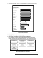
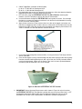
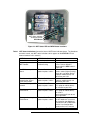
FILTERSCAN® WiFi
Air Filter Monitor
Models FS-245-B & FS-245-C
Reference Guide
Version 3.04
The information contained herein is proprietary and is not to be used for purposes other than as an aid in the
operation and/or maintenance of the of the product described herein and is not to be released or reproduced by
anyone without the written permission of CleanAlert, LLC.
Due to CleanAlert's constant pursuit of product improvement, minor discrepancies may exist between the actual
product, text, and illustrations. All information contained herein is based on the latest specifications at the time of
publication and is subject to change without notice.
FILTERSCAN® and AirFilterSentry™ are trademarks of CleanAlert, LLC.
Table of Contents
Introduction
………………..…………………….…………………………………………………………
In The Box ..............................………………………………………………………………………….
Tools Required ............………………………………………………………………………………….
Safety ………………….………………………………………………………………………………….
Application ………….…………………………….............................................................................
FCC Compliance ……………..…………………………………………………………………………..
IC Compliance ………………..…………………………………………………………………………..
2
Sign Up and Configure AirFilterSentry Notification Service …………….……………..…….
FILTERSCAN WiFi Air Filter Monitor Installation …………………….……………………...
Applying Power - Model FS-245-C (15-24V AC/DC ...............................................................
Applying Power - Model FS-245-B (Battery/Adapter) ...........................................................
Connect to Your Wireless Router .............................…..……………………………...……………
Connect to a Wireless Router "With" a WPS Button .............................................................
Connect to a Wireless Router "Without" a WPS Button ......................................................
Connect to the AirFilterSentry Notification System Server .................................................
Calibrating the FILTERSCAN WiFi ..........................................................................................
Operation -FILTERSCAN WiFi Air Filter Monitor …………………………………..……......
4
System Monitoring ……….……………………………………………………………….……………..
Alarm Modes ………..………………..………………………….………………………………………
Clogged Air Filter …………...……….…………………………………………………………………..
Low Battery ………………..…………………………..………………………………………………….
Battery Replacement ......................................................................................................................
Malfunction ……………..………………………………………………………………………..……….
Calibrating When Installing a New Air Filter ………………….……………………………………….
Automatic Adjustment ………….………………………….…………………………………………….
Software Updates ……………….………………………….…………………………………………….
Frequently Asked Questions ……………….…….……………………………………………………..
Specifications …………….…….……………………………………………………………………………
Warranty ……………..………………………………………………………………………………………
WiFi …………………..….………………….………….…………………………………..…………………
2
2
2
3
3
3
9
11
11
12
12
14
15
16
17
17
17
17
17
18
18
18
19
19
19
21
22
22
Transmitter ……………….……………………………………………………………………………… 22
Remote Update
…………………….…………………………….…………………………………….. 22
Revision History ……………………………....…………………………………………………………… 23
Appendix
………………..…………..………………………….……………………………………. 24
Glossary ……………………………..……………..……………………………………………………..
Indicators ………….…………………………..………………………………………………………….
Local Alarm Indications .................................................................................................................
Various HVAC Configurations ..…….………………………………..…………………………………
Optional Dry Contact Relay Output …………….……………………………………………………….
Disclaimer ……………………….……………….……………………………………………………….
24
24
24
25
28
28
1
Introduction
®
Congratulations on your purchase of the CleanAlert FILTERSCAN WiFi Air Filter Monitor. The
CleanAlert FILTERSCAN WiFi Air Filter Monitor continuously and automatically monitors the
clogging* of an air filter installed into a household or commercial forced air heating, air conditioning, or
heat pump system and provides alerts when the filter clogs and needs to be replaced.
™
The CleanAlert AirFilterSentry Notification Service will send you a text message alert and or
email alert notifying you of the clogging* of an air filter installed into your household or commercial
forced air heating, air conditioning, or heat pump system. The system monitoring service is located at
www.cleanalertwifi.com where you may register your FILTERSCAN WiFi Air Filter Monitor and
sign up for the CleanAlert AirFilterSentry Notification Service. In addition to receiving text and or
email notifications, you can check on the status of your air filter as it becomes more and more dirty
over time before reaching clogged* status.
*NOTE: “Clogging” is defined as when the differential air pressure in the HVAC system doubles
from its calibrated clean or new air filter value.
IMPORTANT!
Please read all instructions carefully to insure years of trouble-free operation.
In The Box
1.
FILTERSCAN WiFi Air Filter Monitor, Model FS-245-B or FS-245-C
2.
3.
4.
5.
6.
7.
4 Energizer Ultimate Lithium "AA" Batteries (FS-245-B model only)
Read This First document - Critical
Quick Start Guide
Drill Template to locate mounting holes in a return air plenum
Mounting Screws
Packaging / box
Optional: CA-360 external AC/DC wall adapter power supply. (If ordered for the Model FS245-B only, it is useful when there is a wall outlet available within 6’ of the FILTERSCAN
mounting location, and it eliminates the need for batteries.)
Optional: CA-4DP Tubing Kit. (If ordered with either FS-245-B or FS-245-C, this 6’ long
Tubing Kit is used to have the FILTERSCAN monitor differential pressure across the air
filter. It is especially useful when the FILTERSCAN is mounted in an attic or crawl space,
or when the air handler is located outside the building (since the FILTERSCAN must be
mounted indoors). Call or email to order longer length tubing.
•
•
Tools Required
1.
2.
3.
4.
5.
6.
7.
Power Drill
7/64” Drill bit
3/8” Drill bit or Step Drill
#2 Phillips Screwdriver
½” Drill Bit (for Model CA-4DP Tubing Kit only)
Eye and Ear Protection
Dust Mask
SAFETY
WARNING! READ AND UNDERSTAND ALL INSTRUCTIONS.
Failure to follow all instructions may result in electrical shock or serious
personal injury.
2
Application
FILTERSCAN WiFi Air Filter Monitor is an air filter clogging detection system. It has been
designed to monitor the change in differential pressure as a result of dirt build up on an air filter
and alert the user when the amount of clogging reaches a pre-determined threshold.
The FILTERSCAN WiFi Air Filter Monitor is compatible with most air filters ranging in
differential pressure drop from 0.10”wg to 4.0”wg and with single and multi-speed blower HVAC
systems, and most VAV (Variable Air Volume) systems. Note: The Monitor must be mounted
downstream if the VAV system is set to the constant torque mode.
The FILTERSCAN WiFi Air Filter Monitor will transmit status conditions through your
wireless Internet router to a cloud-based server database, which in turn sends text and or email
alerts to any smartphone (Android or iOS) or other Internet-connected device, such as a laptop,
tablet, or desktop computer (PC or Mac). In order to utilize this feature you will need: (1) a
wireless router with an operational WiFi Protected Setup (WPS) button, or a wireless router
without a WPS button, plus a separate WiFi enabled device such as a smartphone or laptop, and
(2) a subscription to the AirFilterSentry (AFS) Notification Service. You can check the status
of your air filter at any time by logging into your AFS account requesting a Filter Status report.
FCC Compliance
This device complies with Part 15 of the FCC Rules. Operation is subject to the following two conditions:
(1) this device may not cause harmful interference, and (2) this device must accept any interference
received, including interference that may cause undesired operation.
NOTE: This equipment has been tested and found to comply with the limits for a Class B digital device,
pursuant to Part 15 of the FCC Rules. These limits are designed to provide reasonable protection against
harmful interference in a residential installation. This equipment generates, uses and can radiate radio
frequency energy and, if not installed and used in accordance with the instructions, may cause harmful
interference to radio communications. However, there is no guarantee that interference will not occur in a
particular installation. If this equipment does cause harmful interference to radio or television reception,
which can be determined by turning the equipment off and on, the user is encouraged to try to correct the
interference by one or more of the following measures:
-- Reorient or relocate the receiving antenna.
-- Increase the separation between the equipment and the receiver.
-- Connect the equipment into an outlet on a circuit different from that to which the receiver is connected.
-- Consult the dealer or an experienced radio/TV technician for help.
Changes or modifications not expressly approved by the party responsible for compliance could void the
user’s authority to operate the equipment.
Contains FCC ID Number: T9J-RN171
IC Compliance
This Class B digital apparatus complies with Canadian ICES-003.
Cet appareil numérique de la classe B est conforme à la norme NMB-003 du Canada.
This device complies with Industry Canada license-exempt RSS standard(s). Operation is subject to the
following two conditions: (1) this device may not cause interference, and (2) this device must accept any
interference, including interference that may cause undesired operation of the device.
Cet appareil est conforme à Industrie Canada exempts de licence RSS norme. Opération est soumis aux
deux conditions suivantes: (1) cet appareil ne peut pas causer de brouillage et (2) cet appareil doit
accepter toute interférence, y compris les interférences pouvant causer un fonctionnement intempestif du
dispositif.
Model: FS-245-B
Modèle: FS-245-B
Model: FS-245-C
Modèle: FS-245-C
Contains IC Certification/Registration Number: #6514A-RN171
Numéro de Certification / d'enregistrement les IC: #6514A-RN171
3
Sign Up & Configure AirFilterSentry Notification Service
Enter the Serial Number(s) and MAC Address(es) of your FILTERSCAN WiFi unit(s), which is(are)
located on the back of the Monitor Housing(s) and on the product box.
S/N _________________________________ MAC ____:____:____:____:____:____
S/N _________________________________ MAC ____:____:____:____:____:____
S/N _________________________________ MAC ____:____:____:____:____:____
Please “Register” your FILTERSCAN WiFi Air Filter Monitor on the CleanAlert AirFilterSentry
Notification Service website www.cleanalertwifi.com, “Sign Up” for the service, and configure your
notification preferences and messages.
1. Select “All Warranty Registration” and enter the requested information (This information is
appreciated but not required).
2. Then, if you are installing from one to three Monitors, select “Sign Up For AFS Home/Home+”
or if you are installing more than three Monitors, select “Sign Up For AFS Manager” on the
Home Page.
Sign Up For AFS
Home/Home+
Log In To AFS
Notification Service
Sign Up For AFS
Pro/Pro+
All Warranty
Registration
Sign Up For
AFS Manager
Go to
CleanAlert.com
Figure 1: Home Page - Welcome Screen
3. Enter your profile information on the Sign Up page.
4
SIGN UP BELOW
*required field
*First Name
*Last Name
*Email
*Password
Note; Password must be a minimum of 8 characters. Use a
mixture of upper and lowercase letters, numerals, and
punctuation for security.
*Re-enter Password
*Plan Type
What’s This?
*I have read, understood, and agree to the terms of using this
website.
Read the Privacy Policy
Read the Terms and Conditions
Cancel
Submit
Figure 2: Sign Up Page - Create Login and Password
4. After submitting your profile information on the Sign Up page, you will receive an email with an
activation link. Upon clicking on that link your browser will open as seen below. Note: The
email entered upon Sign Up must be correct, otherwise you will not receive this confirmation
email and will have to start the Sign Up process again.
Thank you for verifying your account.
Now, just sign in to complete the sign up process. Check the “Stay Logged In”
box if you want to stay logged in.
LOG IN
LOG IN BELOW
Email
Password
Stay logged in
Cancel
Submit
Figure 3: From Confirmation Link to Login
5. Log In to your account.
6. On the Home page, select on Monitors. Then, select Add Monitor. Enter the requested
information.
5
ADD MONITOR
*required field
*Location
*Device Name
*Serial #
*MAC Address
*Device Time Zone
(GMT 5:00) Eastern Time (US & Canada)
Format for Notifications
Email
Phone Numbers for Text Notifications
Phone Help appears
here
Phone 1
Phone 2
Phone 3
Email Addresses for Email Notifications
Email Help appears
here
Email 1
Email 2
Email 3
Text/Email Messages
Text/Email Message Help appears here
Clog Notification Text
Location
Device Name %SerialNumber%
Preview:
Battery Low Notification Text
Location
Device Name %SerialNumber%
Preview:
Malfunction Notification Text
Location
Device Name %SerialNumber%
Preview:
Allow automatic updates to your FILTERSCAN software
What’s this?
Submit
Figure 4: Enter Monitor Information
a. You must name the Location – use a name or phrase that helps you identify where the
FILTERSCAN WiFi Air Filter Monitor is located (attic, basement, crawl space, etc.).
b. You must also name the Device – a name or phrase that whatever helps you identify the
FILTERSCAN WiFi Air Filter Monitor (home, beach house, Apt #37, etc.).
c. Enter the Monitor’s Serial Number and MAC address, including the “:” between character
pairs. Both S/N and MAC were recorded previously in this manual, located on the back of
the monitor, and located on the side of the Monitor box.
d. Select the Time Zone where the Monitor is located.
e. Select how you want to be notified: Email, Text, or Both.
f. Enter the smartphone number (up to 3) where you wish to receive text messages.
g. Enter the email address (up to 3) where you wish to receive email messages.
h. Enter the text and email messages you wish to receive.
6
i.
Check the Location and or the Device Name check boxes to automatically add those to
the alert messages you select. The “Preview” shows you how the text and or email will
appear.
j. Check the “Allow automatic updates to your FILTERSCAN software” box if you want to
receive automatic software updates. This remote update feature is transparent to you and
no action is required after updates are installed.
k. Click on Submit. This will send you to the Contact page.
7. Enter Contact Information.
ENTER CONTACT INFORMATION
*required field
George Smith
*First Name
*Last Name
Company
*Email 1
Email 2
Email 3
*Address 1
Address 2
*City
Country
United States
State
Pennsylvania
Province
*Zip Code
*Time Zone
(GMT 5:00) Eastern Time (US & Canada)
*Phone #1
Phone #2
Phone #3
Submit
Figure 5: Contact Information
7
8.
Enter Billing information – [NOTE: This will appear differently depending on account types].
ENTER BILLING INFORMATION
*required field
Same as Contact
*First Name
*Last Name
Company
*Email
*Address 1
Address 2
*City
*Country
*State
*Province
*Zip Code
*Phone #
Submit
Figure 6: Billing Information
9. Click on Submit.
10. Enter credit card information on the payment page.
NOTE: This will appear differently depending on payment types.
11. After payment is accepted, you will be directed back to the Home page.
NOTE: Credit card acceptance and AFS database update may take a few minutes to
complete. Please wait a few minutes before taking further action with your AFS account.
Monitors
Contractor
Connections
Filter Status
Send SMS/
Email Test
Account
Information
Register a
Product
Go To
CleanAlert.com
Figure 7: AirFilterSentry User Home Page
8
12. If you have another Monitor to sign up (Home+ and Manager accounts only), Log out and Log
in. Select “Monitors” from the Home Page, then select “Add Monitor”.
13. Go to Step 6 to sign up additional monitors.
14. If you need to change any information you’ve entered for any monitor, click on “Edit Monitor”
on the Home page.
15. Make the necessary changes and click on Submit.
16. Once all of your Monitors have been signed up, proceed to installation and connecting to your
WiFi router, after which you may begin viewing the online status reports available at
www.cleanalertwifi.com.
NOTE: If you will be using a corporate network to connect the monitor to the Internet, contact your
network administrator prior to enabling the web server of CleanAlert. Company policy may
prohibit the use of web servers for security reasons. CleanAlert is not responsible for the
use of, nor makes any claims as to the security of the web server interface over your
network. The use of the web server is the responsibility of the end user.
FILTERSCAN WiFi Air Filter Monitor Installation
The CleanAlert FILTERSCAN WiFi Air Filter Monitor, Model FS-245, MUST be installed at the
RETURN side plenum, NOT the SUPPLY side (see the Appendix) either upstream of, downstream of,
or differentially across the air filter (using the optional tubing kit Model CA-4DP). The Monitor must be
mounted downstream if the VAV system is set to the constant torque mode.
To help determine which installation position is possible with your HVAC system, refer to Figures 16
through 20, which illustrate various installation configurations, as well as the proper setting of the
Upstream/Downstream switch.
WARNING!
Ensure that the HVAC system blower motor/fan is OFF until told otherwise!
WARNING!
Do NOT insert anything into the Sensor Tube! Doing so will result in sensor
damage and malfunction.
1. Insure you have recorded the Serial Number(s) and MAC address(es) previously in this
document.
2. The FILTERSCAN WiFi Air Filter Monitor should be attached to the external wall of the
return air duct or plenum, either upstream or downstream from the air filter, and at least six
inches from the filter or any other obstructions within the duct or plenum.
3. Locate an area on the return, preferably downstream from the air filter (that is, between the air
filter and the HVAC system blower), large enough to place the Monitor template on a flat
surface and where there are NO obstacles inside the duct or plenum. There should be
sufficient clearance (6” minimum) from the surrounding walls and from any components within
the HVAC system. If there is an obstruction such that the Monitor cannot be installed as
described above, you may need to complete the installation using the optional CA-4DP Tubing
Kit.
4. Tape the Monitor template at the location found in the previous step, such that "TOP" is facing
upward. The FILTERSCAN WiFi Air Filter Monitor front panel must be clearly visible
when installed.
5. Using the template, Drill one 3/8” hole for the sensor.
6. For sheet metal plenum installation, drill four small holes (7/64") for the mounting screws
provided.
a. Attach the FILTERSCAN WiFi Air Filter Monitor by aligning its sensor tube with the
larger hole and secure the Housing using the mounting screws supplied. The sensor tube
does not extend into the duct.
7. For Duct Board plenum installation, follow the directions below. Otherwise go to Step 8.
9
a. Obtain Toggle Bolts (available at Home Depot)
(1) #1/8" x 2" SKU 261181 Package of 25 or
(2) #1/8" x 3" SKU 261203 Package of 25
b. Use toggle bolts that are one inch longer than the thickness of the duct board to allow the
toggle to expand after inserting through mounting hole.
c. Drill 3/8" holes at the four FILTERSCAN WiFi Air Filter Monitor mounting hole
locations (see Drill Template) as well as the Sensor Tube location.
d. Insert the bolt alone through the FILTERSCAN housing from the inside. Once through
the housing, screw on the toggle a few threads such that the fins fold toward the housing.
Do this for all four mounting holes.
e. Apply silicone sealant or air duct sealer to the inner sides of the toggle (see below) such
that when the toggle expands inside the duct, the silicone will seal the hole and secure the
toggle to the inside of the duct to help prevent the toggle from dropping into the duct if the
screw is removed at a later date after the sealant has cured.
Figure 8: Toggle bolt for duct board installation
f.
Insert each toggle through the duct board holes, insuring the Sensor Tube aligns with the
Sensor Tube hole.
g. Once all four toggles are fully inserted through the duct board, lightly pull the housing away
from the duct board while tightening each bolt, until all four are securely fastened, without
crushing the duct board. Make sure the Sensor Tube seal has been squeezed between
the housing and duct board to insure no air leakage.
Figure 9: Side view of FILTERSCAN WiFi monitor
8. IMPORTANT! Set the Upstream/Downstream switch shown in Figure 10 so that it matches
the FILTERSCAN WiFi Air Filter Monitor’s position with respect to the air filter (that is, OFF
for upstream mounting or ON for downstream or differential mounting). Please see the
APPENDIX for 'Various HVAC Configurations for Monitor Installation' configurations.
10
Figure 10: Inside of the FS-245-C FILTERSCAN WiFi monitor
Applying Power – Model FS-245-C (15-24V AC/DC)
SAFETY
This model product should only be installed by a licensed electrician.
1. This model is powered from the HVAC system’s auxiliary 15 to 24 VAC/DC power supply and should
2.
3.
4.
5.
be installed by a qualified electrician. A typical installation will have that power run through an installerprovided conduit to the FILTERSCAN WiFi Air Filter Monitor.
Locate the six terminals on the left-hand bottom corner of the printed circuit board illustrated in
st
rd
nd
Figure10. Connect 15 to 24V AC or DC to the 1 and 3 leftmost terminals as shown. The 2 leftmost
terminal is for earth ground connection, if available.
The three terminals on the rightmost terminals are for connecting the optional dry contact relay output.
Reference Figure 21 in the APPENDIX.
When power is applied, the beeper should sound momentarily and the STATUS LED should come on
green momentarily, then turn on and remain red. This indicates that the unit has not yet been
calibrated to the air filter and HVAC system upon which it is installed. Additionally, the WiFi Status LED
will blink a series of Red and Green. Wait until all blinking has stopped.
Go to Section Connect to a Wireless Router.
Applying Power – Model FS-245-B (Battery/Adapter)
1. This model is powered from either four AA batteries or an optional wall mount power adapter. If the
adapter is installed, the batteries may remain in place or be removed. Insert four (4) AA batteries in
the battery holder, making sure the positive and negative directions are exactly as illustrated in Figure
®
11. CleanAlert recommends using Energizer ULTIMATE LITHIUM batteries. See section “Operation
- FILTERSCAN WiFi Air Filter Monitor” for battery replacement.
2. When power is applied, the beeper should sound momentarily and the STATUS LED should come on
green momentarily, then turn on and remain red. This indicates that the unit has not yet been
calibrated to the air filter and HVAC system upon which it is installed. Additionally, the WiFi Status LED
will blink a series of Red and Green. Wait until all blinking has stopped.
3. Battery life is approximately one year when utilizing the Energizer ULTIMATE LITHIUM batteries. The
use of other batteries, such as Alkaline, will significantly decrease battery life.
11
Figure 11: Inside the FS-245-B Monitor
Connect to a Wireless Router
Determine whether your router has a WPS button and where it is located. See page 14 if your router does
not have a WPS button.
You are now ready to initiate communications between your FILTERSCAN WiFi Air Filter Monitor
through your LAN (Local Area Network) via your wireless router to the AirFilterSentry Notification
Service server. You must Sign Up to create an account on the AirFilterSentry Notification Service
server prior to performing the following.
Connect to a Wireless Router “With” a WPS Button
1. Depress the WPS button on your router for two to ten seconds until its WiFi LED begins to blink. See
your router user’s manual if you do not know what that button looks like. Timing varies with router
manufacturers.
2. Reference Figure 12 to locate the FILTERSCAN WiFi Air Filter Monitor WPS button.
3. Within several seconds (time depends on your specific wireless router), using a nonmetallic
instrument such as a pencil eraser, toothpick, or other non-metallic object, depress the WPS button
just once until you feel a click and immediately release. A series of red, green, and amber WiFi
Status Indicator flashes will occur, and finally go out. If a series of red WiFi Status LED flashes occur
at the end of the flashes, refer to Table 1 WiFi Status Indications for further steps.
4. Your FILTERSCAN WiFi Air Filter Monitor is now connected to your wireless router, and has
initiated a connection process where the FILTERSCAN WiFi Air Filter Monitor and your
wireless router communicate with each other and establish a connection with no further action
needed.
NOTE: If you will be using a corporate network to connect the monitor to the Internet, contact your
network administrator prior to enabling the web server of CleanAlert. Company policy may
prohibit the use of web servers for security reasons. CleanAlert is not responsible for the use
of, nor makes any claims as to the security of the web server interface over your network.
The use of the web server is the responsibility of the end user.
5. Go to “Connect to the AirFilterSentry Notification System Server”. See page 15.
12
WiFi Status Indicator
Zero/Clean Button
WPS Button
Figure 12: WiFi Status LED and WPS Button Locations
Table 1 WiFi Status indications (Locate the internal WiFi Status Indicator above. The Heartbeat
and other normal, non-WiFi status indications which appear on the STATUS LED are
shown elsewhere in this manual.)
WiFi Status
None
Attempting connection to
WiFi network
LED Blink Indication
Normal operation
Continuous slow
Yellow flashing
No WPS access point
found
Flashes Red 4 times,
pattern repeats 3 times.
Error Connecting to WiFi
network after Access
Point configuration
Error Connecting to WiFi
network
Flashes Red 2 times,
pattern repeats 3 times.
Error Connecting to the
Cloud Server
Flashes Red 5 Times,
pattern repeats 3 times.
Message refused by the
Cloud Server
Flashes Red 6 Times,
pattern repeats 3 times.
In process of resetting
Continuous Fast Red
Flashes Red 3 Times,
pattern repeats 3 times.
Notes
In process of connecting to the
Access Point or Wireless
Router after the WPS button is
depressed
Did not find the access point or
wireless router (highest priority).
Check to insure other devices
(laptop or mobile device) can
connect to your LAN
Check to insure other devices
(laptop or mobile device) can
connect to your LAN
Check to insure other devices
(PC, laptop or mobile device)
can connect to your LAN
Check to insure other devices
(PC, laptop or mobile device)
can access
www.cleanalertwifi.com to test
server operation
MAC address not yet entered in
the AFS database. Insure that
you signed up your Monitor as
directed in the AFS Notification
Service User Configuration
section earlier in this manual
No action required
13
WiFi Status
WiFi
WiFi set to factory
defaults
LED Blink Indication
Flashing
Continuous slow Yellow
flashing
Downloading firmware
update file
Connecting to server
Continuous Fast Yellow
Flashing
Fast Green Flashing
Notes
Connect to FILTERSCAN WiFi
network and configure the
FilterScan device.
No action required
No action required
Connect to a Wireless Router “Without” a WPS Button
Follow these steps if your wireless router DOES NOT have a WPS button. This is referred to Ad Hoc
Association.
1. Items needed:
a. A WiFi-enabled device with web browsing capabilities, such as a laptop, smartphone, or tablet
b. The wireless password or passphrase for your router
c. The SSID of your wireless router (look on the side or bottom of the router or consult its
manual)
2. Reference Figure 12 to locate the FILTERSCAN WiFi Air Filter Monitor WPS button.
3. Depress and hold the WPS button until the WiFi Status Indicator blinks green then fast red. This may
take up to 30 seconds. Release the button and wait until the WiFi Status Indicator blinks amber.
4. Using your WiFi-enabled device, connect to the “FILTERSCAN” network. On an iPhone or iPad you
do this by going to the Settings app. It may take a few minutes for the FILTERSCAN network to
appear.
5. Once the WiFi-enabled device is connected to the FILTERSCAN network, open a web browser on
your WiFi-enabled device.
6. Enter the IP address 192.168.1.1 in the URL box
Loading Pre-scanned Networks
Figure 13: FILTERSCAN WiFi Network Configuration Page
7. Wait for the page to update and show the available networks. You are looking for the SSID of your
router. This may take several minutes. If the expected network is not available, press the “Refresh”
button.
Join Network
Refresh
Figure 14: FILTERSCAN WiFi Network Configuration Page
8. Enter your router’s password and press the Join Network button.
Supported network types for ad hoc association:
• WEP128
• WPA-PSK (TKIP)
• WPA2-PSK (AES)
• WPA-PSK mixed mode (some access points, not all are supported)
14
For WEP networks, the security key entered is the hexadecimal key, not the passphrase used to
generate the key. WEP128 keys must be 26 digits long consisting of characters 0-9 and A-F.
The FILTERSCAN WiFi Air Filter Monitor does not support spaces in the WPA or WPA2
passphrases.
9. Your FILTERSCAN WiFi Air Filter Monitor is now connected to your wireless router, and has
initiated a connection process where the FILTERSCAN WiFi Air Filter Monitor and your
wireless router communicate with each other and establish a connection with no further action
needed.
NOTE: If you will be using a corporate network to connect the monitor to the Internet, contact your
network administrator prior to enabling the web server of CleanAlert. Company policy may
prohibit the use of web servers for security reasons. CleanAlert is not responsible for the use
of, nor makes any claims as to the security of the web server interface over your network.
The use of the web server is the responsibility of the end user.
Connect to the AirFilterSentry Notification System Server
1. Upon successful sign up, subscription, configuration, installation, power up, and Internet connection,
the FILTERSCAN WiFi Air Filter Monitor will be connected to the AirFilterSentry Notification
System server through your wireless router and should require no further attention. The Monitor will
start sending status messages to the server on a periodic basis.
2. To test the Internet connection:
a. Although the wireless transmission range should cover your building, it is greatest with minimum
obstructions between the FILTERSCAN WiFi Air Filter Monitor and the wireless router. Any
obstructions, such as walls, floors, and ceilings can reduce the range of transmission, and
relocation of the wireless router may be required. Retest with each location to ensure proper
operation.
b. Depress the SEND button of the FILTERSCAN WiFi Air Filter Monitor once at any time to
send its status to the AirFilterSentry Notification Service server database.
c. Then, login to your account* at www.cleanalertwifi.com to view your monitor’s status.
NOTE:
Your FILTERSCAN WiFi Air Filter Monitor status display at the AirFilterSentry
Notification Service is capable of displaying more than 100% clogged. This is possible
since the “100% clogged” point is the recommended point when it is most efficient to service
(replace or clean) the air filter. If you ignore the notification and continue to operate your
HVAC system, the air filter will become dirtier and the status will rise above 100% clogged.
To provide the most efficient air filtration and HVAC system operation, you should service the
air filter as soon as possible after being notified of a clogged condition.
*Subscription to the AirFilterSentry Notification service is required to enable this feature
15
Calibrating the FILTERSCAN WiFi Air Filter Monitor
Figure 15: Front cover of the FILTERSCAN WiFi monitor
1. After power is applied, wait for approximately 15 seconds (warm up and stabilization time).
2. Turn the HVAC system OFF at the thermostat. Ensure the HVAC system blower is turned OFF and
that no conditions exist during this part of the calibration that would cause air to be moving within the
HVAC ducts, such as opening and closing of doors or windows.
3. Install a clean, new air filter into the system.
4. Depress the ZERO/CLEAN button ONCE.
5. If the STATUS LED turns Red, depress the ZERO/CLEAN button ONCE again.
a. The STATUS LED will blink yellow for several seconds while the FILTERSCAN WiFi Air Filter
Monitor records the HVAC system’s FAN OFF condition, then turns to blinking green. This
indicates proper operation and that you are ready to move to next step. If the unit detects the zero
air flow is out of limits, the STATUS LED will blink red. In this case, check to see that the system
blower fan is OFF and that no condition described in step 1 exists. If no such condition exists, start
again at step 1. If the error condition persists, call 888-414-FLOW (3569) for instructions.
6. Adjust the thermostat temperature adjustment to either increase or decrease the room temperature by
at least ten degrees, enough to signal the HVAC system to turn on heating or cooling at maximum
blower fan speed.
7. Once the HVAC system blower fan turns on, wait at least one minute, or until the blower fan reaches
maximum speed, for the blower fan to stabilize. This is critical to proper operation in VAV blower
systems.
8. Depress the ZERO/CLEAN button once. The STATUS LED should turn from blinking green to
blinking yellow for about eight (8) minutes. This indicates that the unit is calibrating itself to the air
filter and HVAC system into which it is installed.
9. Once calibration is completed, the STATUS LED will change from blinking yellow to blink green a few
times then turn off.
10. Return the thermostat to normal operating temperature.
This concludes the installation of the FILTERSCAN WiFi Air Filter Monitor.
The SERVICE FILTER control is a fine tuning adjustment that has been calibrated during production to the
mid-range, which is the Recommended Setting. This control allows the user to change the point at which
the clog alarm will be triggered. Turning the SERVICE FILTER adjustment knob clockwise will cause the
FILTERSCAN WiFi Air Filter Monitor to issue an alarm at a lower level of filter clogging (less energy
consumption). Turning the SERVICE FILTER adjustment knob counter-clockwise will cause the
FILTERSCAN WiFi Air Filter Monitor to issue an alarm at a higher level of filter clogging (more
energy consumption). See the FAQ Section for further information.
16
Operation - FILTERSCAN WiFi Air Filter Monitor
System Monitoring
The STATUS LED will blink green approximately once per minute (called a
heartbeat) to indicate that the unit is functioning properly. Usually the
FILTERSCAN WiFi Air Filter Monitor will be in the standby mode,
conserving power. It wakes up periodically to monitor air filter condition,
battery level, and system operation. If no alarm conditions are detected,
the FILTERSCAN WiFi Air Filter Monitor goes back to sleep after
several minutes of monitoring.
NOTE: Should there be a power failure the FILTERSCAN WiFi Air
Filter Monitor will save all parameters such as the clean air filter
calibration and the current state of the air filter. When power is restored,
the FILTERSCAN WiFi Air Filter Monitor will continue operation with
no user action required. The same applies when replacing depleted
batteries.
Alarm Modes
The FILTERSCAN WiFi Air Filter Monitor provides both audible and
visual local alarms indicating a clogged air filter, a low battery, or a system
malfunction. In addition, the AirFilterSentry Notification Service allows
remote monitoring* of system conditions. *Subscription to the AirFilterSentry
Notification service is required to enable this feature.
NOTE: The HVAC system blower fan must be running when the
FILTERSCAN WiFi Air Filter Monitor attempts to check air filter
condition. Since the FILTERSCAN WiFi Air Filter Monitor checks the
air filter condition periodically, it may take several days to detect, trigger,
and alert a clogged filter condition.
NOTE: The FILTERSCAN WiFi Air Filter Monitor has a light sensor
which prevents audible alarms when there is no light present at the Monitor
location. This prevents awaking occupants while sleeping and prevents
needless beeping in a crawl space, attic, or other unoccupied location.
The visual Status LED will still operate normally regardless of lighting
conditions.
Clogged Air Filter
When the FILTERSCAN WiFi Air Filter Monitor detects a clogged air
filter, an alert condition is triggered. The red STATUS LED will illuminate,
blinking five times approximately every ten minutes until the alert condition
is reset. There will also be an audio alert which corresponds to the visual
alert indication. The clogged filter alert is reset by following the instructions
in the section "Calibrating When Installing a New Air Filter" below. In
addition, a text and or email will be sent to a designated person if you have
signed up for the AirFilterSentry Notification Service.
NOTE: A new or cleaned air filter should always be installed whenever the
CALIBRATE operation is performed.
Low Battery
When the FILTERSCAN WiFi Air Filter Monitor detects a low battery
condition, an alert condition is triggered. The STATUS LED will blink
yellow approximately once per minute to indicate a low battery in the
Monitor. Replacing the Monitor batteries (see APPENDIX) will reset the
alert condition. In addition, a text and or email will be sent to a designated
person if you have signed up for the AirFilterSentry Notification Service.
17
Battery
Replacement
Access : Remove the front cover from the FILTERSCAN WiFi Air Filter
Monitor housing. Remove the batteries.
®
Installation: Insert four (4) Energizer ULTIMATE LITHIUM batteries in
the battery holder of the FILTERSCAN WiFi Air Filter Monitor,
observing polarity, and replace the front cover.
Malfunction
When the FILTERSCAN WiFi Air Filter Monitor detects an internal
malfunction, an alert condition is triggered. The red STATUS LED will
illuminate continuously until the malfunction is corrected. In addition, a text
and or email will be sent* to a designated person if you have signed up for
the AirFilterSentry Notification Service. In the unlikely event this should
occur, remove power from the FILTERSCAN WiFi Air Filter Monitor
by removing the batteries, unplugging the optional AC Adapter, or in the
case of 15-24V AC/DC-powered models (“-C”) contacting your HVAC
system electrician to have the power to the Monitor turned off. Wait for a
minute and restore power. If your FILTERSCAN WiFi Air Filter
Monitor unit is operating with both AC Adapter and batteries installed,
both will need to be removed in order to reset the malfunction. If this does
not reset the malfunction alert, call 888-414-FLOW (3569) for instructions.
Calibrating When
Whenever a new air filter is installed, the FILTERSCAN WiFi Air
Installing a New Air Filter Filter Monitor must be calibrated. Calibration establishes the clogged air
filter detection threshold based upon the condition recorded for a new air
filter. When a new air filter is installed, its condition is recorded and saved
in nonvolatile memory. Reference the instructions on the monitor cover.
1.
2.
3.
4.
5.
6.
7.
8.
9.
10.
11.
12.
13.
14.
15.
Ensure that the HVAC system is OFF at the thermostat.
Remove the dirty air filter from the HVAC system.
Install a new, clean air filter into the HVAC system.
Make sure the FILTERSCAN WiFi Air Filter Monitor power is
ON and the low battery indication is not being displayed.
Depress the ZERO/CLEAN button on the FILTERSCAN WiFi Air
Filter Monitor.
Wait for the red STATUS LED to illuminate.
Depress the ZERO/CLEAN button again.
Wait several seconds for the STATUS LED to change from blinking
yellow to blinking green.
Turn the HVAC system ON at the system thermostat.
Set the thermostat temperature adjustment to either increase or
decrease the room temperature by ten degrees, which should be
enough to signal the HVAC system to turn heating or cooling on.
Wait one minute for the HVAC system blower fan to turn on and
stabilize. (For VAV blower systems, it may take a few minutes for the
blower fan to reach maximum speed.)
Depress the ZERO/CLEAN button again.
Wait approximately eight (8) minutes for the STATUS LED to turn
from blinking yellow to blinking green. During this time, the unit is
recording the condition of the clean air filter.
Wait several seconds for the blinking green STATUS LED to turn
OFF.
Return the thermostat to normal operating temperature.
Your FILTERSCAN WiFi Air Filter Monitor is now calibrated to the
type of air filter you have installed. Depending on the air filter type and
18
manufacturing tolerances, you may need to calibrate the FILTERSCAN
WiFi Air Filter Monitor each time a new air filter is installed.
Automatic
Adjustment
ATTENTION - HVAC systems with two-speed blowers! Typical HVAC
systems will have different blower speeds for Heat and A/C. The
FILTERSCAN WiFi Air Filter Monitor automatically adapts to the
changes in HVAC blower speeds.
Software Updates
The FILTERSCAN WiFi Air Filter Monitor has the capability of
automatically updating its software through its Internet connection to the
AirFilterSentry cloud server. If you checked the “Allow Automatic Updates
to your FILTERSCAN Software?” box on the Edit Monitor screen and
there is a later version of software available on the server, your
FILTERSCAN WiFi Air Filter Monitor will automatically download the
latest version of software and update itself without any action by you. The
update will be transparent and all operating parameters will be intact after
the update.
Frequently Asked Questions
All Models
Can the FILTERSCAN WiFi Air Filter Monitor be mounted on the
supply side of the HVAC blower?
No, only on the return side duct, either upstream or downstream of the
air filter or differentially across the air filter.
Can I install the FILTERSCAN WiFi Air Filter Monitor on a multispeed blower HVAC system?
Yes.
Can I install the FILTERSCAN WiFi Air Filter Monitor on a Variable
Air Volume (VAV) HVAC system?
As of the writing of this manual, the FILTERSCAN WiFi Air Filter
Monitor will operate with most VAV systems in production. Note: The
Monitor must be mounted downstream if the VAV system is set to the
constant torque mode.
What effect, if any, does opening or closing air vent registers have on the
FILTERSCAN WiFi Air Filter Monitor performance after it has been
calibrated to a new air filter?
Any significant changes in HVAC system pressure caused by register
changes or other factors will change the point at which the clog alert
will occur. The greater the number of system registers, the less effect
on the system’s pressure when one or two registers are changed and
therefore the less effect on when the clog alert will occur. Regular
changes to system registers could make the performance
unpredictable.
What if my FILTERSCAN WiFi Air Filter Monitor stops sending
status data? What if the Status report at my AirFilterSentry Notification
Service account does not display a recent update Date?
There could be many causes for data to not reach the AFS server.
1. First, depress the SEND button on the FILTERSCAN WiFi Air
Filter Monitor front panel. Wait for one minute then recheck the
AFS Status Display for a current update time and date.
19
2. Next, check the FILTERSCAN WiFi Air Filter Monitor
power. Insure batteries or power to the Monitor is good (Status
LED blinks green approximately once per minute).
3. Turn power off to the FILTERSCAN WiFi Air Filter Monitor
power for one minute. Then turn power back on.
4. Turn power off to your wireless router for one minute. Then turn
power back on.
5. View your AirFilterSentry Notification Service subscription as
it may have expired.
If none of the above result in updated status data, please review
Table 1 WiFi Status indications above for various WiFi Status LED
conditions.
Can I install the FILTERSCAN WiFi Air Filter Monitor on a multispeed blower HVAC system?
Yes.
Where should I set the Service Filter knob?
At the recommended setting in the center of travel. This equates to
the doubling of the initial differential pressure to cause a clog alert.
If you want to waste energy, or think your filter is not dirty enough
when a clog alert occurs at the Recommended setting, you may turn
the Service Filter knob CCW toward “Less Often”. This increases the
differential pressure needed to cause a clog alert. Results? A more
dirty filter, more energy usage, and decreased IAQ.
If you want to save more energy at the expense of higher air filter
costs, or think your filter is too dirty when a clog alert occurs at the
Recommended setting, you may turn the Service Filter knob CW
toward “More Often”. This decreases the differential pressure needed
to cause a clog alert. Results? A cleaner filter, higher air filter costs,
less energy usage, and increased IAQ.
Overall, the Service Filter knob should be to set it at the
Recommended setting for the best balance between wasted energy
and higher air filter costs.
Model FS-245-C
How is the conduit mechanically connected to the FILTERSCAN WiFi
Air Filter Monitor?
There is a conduit connector knock-out located on the lower side of
the monitor housing.
What voltage is acceptable to power the FILTERSCAN WiFi Air Filter
Monitor via the conduit?
Typically 24V AC/DC, although an input voltage as low as 15V DC is
acceptable.
Model FS-245-B
Do I have to install batteries if I power the Monitor from the optional AC
Adapter?
No.
Can I utilize both the AC Adapter and batteries for backup?
Yes, you can install batteries even though you also have an AC
adapter installed. Such power backup is unnecessary however
because the monitor’s non-volatile memory stores all operating
parameters in the event of a power failure.
20
Wireless Router
What should I do if I am unable to connect my monitor to my wireless
router?
Determine whether your routers wireless security has either not been
set or set to WPA-PSK (TKIP) or WPA2-PSK (AES). To do this, you
will need to consult your routers manual. If your routers wireless
security has been set to any other method, you will need to change it
to WPA-PSK (TKIP) or WPA2-PSK (AES).
How far can the FILTERSCAN WiFi Air Filter Monitor be mounted
from the wireless router?
The range of the WiFi signal is similar to the range of your wireless
devices (laptop, smartphone, etc.). However, obstacles such as walls
between the Router and Monitor could decrease the effective range of
the device.
Multiple Monitors
What if my building has multiple HVAC systems, each with their own
FILTERSCAN WiFi Air Filter Monitor. Will the AirFilterSentry
Notification Service allow access of all Monitors within one account?
Yes, the number of monitors though depends upon the type of
subscription you’ve purchased.
Specifications
Pressure Differential Range
Clog Filter Trigger Point
Temperature Range
Humidity
Power Requirements (-B)
Batteries, Monitor (-B)
Battery Life
Power Requirements (-C)
Insertion Depth into Duct
Clogged Air Filter Alert
Low Battery Alert
Malfunction Alert
Mounting
Monitor Dimensions
WiFi Module
WiFi Authentication
Transmission Range
FCC Identification #
Industry Canada #
0.1 to 4.0 in H2O
1.5 to 2 times initial differential pressure (at the recommended setting
on the SERVICE FILTER control)
o
o
o
o
32 to +122 F (0 to +50 C) Operating
o
o
o
o
-40 to +185 F (-40 to + 85 C) Storage
80% RH, non-condensing
6.0 VDC at 90 mA Transmitting, <20 uA Standby
(4) AA 2400 mAH
Approximately 1 year
15 to 24 VAC/DC at 11 mA Transmitting, <20 mA Standby
Does not extend into duct
Red STATUS LED & 2 KHz Beeper alternating ON & OFF five times
Yellow STATUS LED blinking approximately once per minute
Red STATUS LED continuously illuminated
5 holes, 4 @ 7/64” and 1 @ 3/8"
6” x 4.625” x 1.5”
FCC/CE/IC certified 2.4-GHz IEEE 802.11b/g transceiver
Secure using WPA2-PSK (AES)
Within your building similar to other WiFi devices, depending upon
line-of-sight and obstacles
Contains FCC ID Number: T9J-RN171
Contains IC Certification/Registration Number: #6514A-RN171
21
Warranty
Limited warranty
Please refer to www.cleanalert.com/termsofsale.html for full warranty text.
For a period of one (1) year following the date of purchase of the Product, if the Product ceases to function
and/or functions improperly due to a defect in material or workmanship, CleanAlert, LLC will repair or
replace the Product (at its sole discretion) free of charge to the customer. This warranty does not apply to:
1. Damage caused by accident, abuse or mishandling of the Product after it has left CleanAlert,
LLC’s facility;
2. Acts of God;
3. Units which have been subject to unauthorized repair and/or have been taken apart or otherwise
modified;
4. Units damaged from installation or use not in accordance with these instructions;
5. Damages exceeding the cost of the Product; and
6. Damages that are considered normal wear and tear (in CleanAlert, LLC’s sole discretion).
A Product requiring warranty service shall be sent by the customer to CleanAlert’s facility in West Chester,
PA. This warranty does NOT cover the costs of having the Product transported to CleanAlert, LLC for
warranty service. The customer is responsible for safely sending the Product to CleanAlert, LLC.
WiFi
Transmitter
The FILTERSCAN WiFi Air Filter Monitor contains a WiFi radio module operating at a frequency
of 2.4GHz, which is activated periodically. Transmissions to the AirFilterSentry Notification
Service, are very short in duration.
Each FILTERSCAN WiFi Air Filter Monitor has been assigned a unique MAC address at the
time of manufacture.
Remote Update
The FILTERSCAN WiFi Air Filter Monitor has the ability to allow the AirFilterSentry
Notification Service to update the Monitor software. During user configuration on the
AirFilterSentry Notification Service website, if you checked the “Allow Automatic Updates to your
FILTERSCAN Software?” box on the Edit Monitor screen and there is a later version of software
available on the server, your FILTERSCAN WiFi Air Filter Monitor will automatically download
the latest version of software and update itself without any action by you. The update will be
transparent and all operating parameters will be intact after the update.
1. Software updates will be made available by the AirFilterSentry Notification Service.
2. When an update is made available, the Notification Service will send an update command to
the FILTERSCAN WiFi Air Filter Monitor in response to the Monitor’s periodic status
message.
3. If you’ve elected to receive automatic updates, the Monitor then downloads and validates the
new software.
4. No further action is required on your part.
22
Revision History
Rev. #
3.00
3.03
3.04
Effective
12/19/14
1/23/15
2/5/15
Summary:
Original Approved Release
Rearrange to best order of sign up and installation
Final Review for Publishing
23
Appendix
Glossary
HVAC ………................
Heating, ventilating, and air conditioning
Dirty Air Filter ...............
An air filter which has been in use and has collected some amount of dirt
or dust particles that discolor the filter fibers or element but do not
substantially affect the air flow through it.
Clogged Air Filter .........
An air filter which has collected a sufficient amount of dirt or dust particles
to not only discolor the filter fibers or element but decrease the air flow
through the filter as well. The FILTERSCAN WiFi Air Filter Monitor
typically identifies a filter as clogged when the differential pressure within
an HVAC system increases to 1.5 to 2 times the initial differential pressure
identified when the unit was calibrated with a clean filter.
Monitor .........................
The sensor voltage detection and signal processing portion of the system.
AirFilterSentry...............
The application software and database residing on the Cloud Server that
provides all operational aspects of the AirFilterSentry Notification
Service.
Cloud Server.................
The computer server on which the AirFilterSentry Notification Service
resides and operates. The hosting service ensures database backups and
redundancy to provide maximum up-time of their systems.
MAC Address ...............
Media Access Control unique identifier assigned to the WiFi radio within
the FILTERSCAN WiFi Air Filter Monitor.
Indicators
Green STATUS LED......
The blinking Green STATUS LED at the FILTERSCAN WiFi Air Filter
Monitor indicates normal operation.
Yellow STATUS LED.....
The blinking Yellow STATUS LED at the FILTERSCAN WiFi Air Filter
Monitor indicates a process is occurring and can also indicate a low
battery condition at the Monitor or Receiver.
Red STATUS LED........
The Red STATUS LED at the FILTERSCAN WiFi Air Filter Monitor
is an alarm indicator which blinks whenever an alarm condition occurs.
Beeper ..........................
The audible beeper at the FILTERSCAN WiFi Air Filter Monitor is an
alarm indicator which beeps whenever certain alarm conditions occur.
Local Alarm Indications
Monitor/Transmitter Alarm Indications
Alarm Condition
Normal Operation
Clogged Filter
Low Battery
Sensor Failure
Alarm Indication
STATUS LED flashes green every minute.
STATUS LED flashes red five times every
ten minutes. Beeper sounds with LED flash.
STATUS LED flashes yellow every minute.
STATUS LED continuously on red.
Clear Alarm Procedure
None
Replace Filter and
Recalibrate
Replace Batteries
Contact CleanAlert at 888414-3569
24
Various HVAC Configurations for Monitor Installation
Figure 16: Installation on HVAC systems with vertical return and supply ducts
Figure 17: Installation on HVAC systems with horizontal return and vertical supply ducts
25
Figure 18: Installation on HVAC systems with horizontal return and supply ducts
Figure 19: Installation on HVAC systems with wall or ceiling-mounted air filters
26
Figure 20: Installation of the optional CA-4DP Tubing Kit mounted differentially across the filter.
27
Optional Dry Contact Relay Output Operation
1. When connecting the relay output to an external building automation system (BAS) or alarm, it
is recommended that the Common and Normally Closed contacts be used. This allows the
external system or alarm to detect when the cabling is cut.
2. During a clog alarm, the relay will activate for one second, opening the Normally Closed
contacts, and closing the Normally Open contacts.
3.
Note: If the power is lost, there will be no relay indication of such power failure.
N.C.
Common
N.O.
Figure 21: Model FS-245-C with Optional Relay Output
Disclaimer
While CleanAlert makes every effort to ensure the smooth operation of the AirFilterSentry™ Notification Service software, it
makes no warranty as to its effectiveness for a particular purpose; and makes no warranty as to its availability, because it is hosted
on a third party system over which CleanAlert has no control. CleanAlert will not be held accountable for any damage that may or
may not result from the unavailability of this service.
The data contained herein are furnished for information only and are believed to be reliable. We cannot assume responsibility for
the results obtained by others over whose methods we have no control. It is the user's responsibility to determine suitability for the
user's purpose and to adopt such precautions as may be advisable for the protection of property and of persons. In light of the
foregoing, the warranty of CleanAlert, LLC on this product shall be exclusive and in lieu of any other warranties, including, without
limitation, any warranty of fitness for a particular purpose or warranty of merchantability or any other warranties which may be
claimed to arise by operation of law, custom, trade usage, or course of dealing between CleanAlert, LLC and the customer. In no
event shall CleanAlert, LLC be liable, whether in contract or tort (including negligence) for damages in excess of the amount of
money that CleanAlert, LLC charged for the product(s), or for any indirect, incidental, special or consequential damages of any kind,
or loss of revenue or profits, or other financial loss arising out of or in connection with the ability or inability to use the product(s), to
the full extent these damages may be disclaimed by law. The discussion herein of various applications is not to be interpreted as
representation that they are free from domination of patents owned by others or as a license under any CleanAlert, LLC patents that
may cover such applications. We recommend that each prospective user test his proposed application before use, using this data
as a guide.
CleanAlert products are manufactured under one or more of the following U.S. Patents: 7,178,410; 7,490,512; and others pending.
Specifications are subject to change without notice.
© 2012-2015 CleanAlert, LLC
28