1
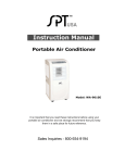
05-09-294 wa-1300 R Instruction Manual P O RTA B L E Air Conditioner Model No. WA-1300E Model No. WA-1310E Model No. WA-1300H Model No. WA-1310H ʳ It is important that you read these instructions before using your new purchase and we strongly recommend that you keep them in a safe place for future reference. 05-09-294 wa-1300 TABLE OF CONTENTS THANK YOU ENERGY SAVING TIPS………..……………………………………………….. 2 SPECIFICATIONS..……………………………………………………………….3 BEFORE USE……….……………………………………………………………. 4 PARTS………..…………………………………………………………………….5 INSTALLATION.…………………………………………………………………...6 MOUNTING OF THE EXHAUST PIPE ………………………………………... 7 INSTALLATION OF THE CARBON FILTER…………………………………...8 OPERATION ………………………………………………………………………9 NOTICE.…………………………………………………………………………..12 DRAINAGE………………………………………………………………………. 13 MAINTENANCE…………………………………………………………………. 15 TROUBLE SHOOTING………………………………………………………….16 DEFECTIVE NOTICE…………………………………………………………... 17 GUARANTEE……………………………………………………………………. 18 SAFETY POWER SUPPLY CORD……………………………………………………………........................19 1 05-09-294 wa-1300 THANK YOU Thank you for choosing the portable air conditioner from SPTUSA, a leading brand in indoor air treatment. We would like you to enjoy the many benefits this unit offers, so please take the time to read this manual carefully and take full advantage of the many advanced features that your SPTUSA Air Conditioner offers you. SPTUSA specialize in complete indoor environment control, manufacturing world-class air conditioners, dehumidifiers and air purifiers with innovative technology. In designing these advanced products, we have listened carefully to our customers and have passed their views onto our research and development laboratories. We wish you many years of enjoyable use. After reading this manual, please keep it in a safe place for future reference. Energy Saving Tips Please use the unit in the recommended room size. (Refer to PAGE 3). Do not locate the air conditioner where furniture or other objects can obstruct the airflow. Keep blinds/curtains closed during the sunniest part of the day. Close fireplace damper and floor or wall grills so that cool air does not escape through the chimney or ductwork. Keep filters clean. Set the unit to maximum cooling and high-speed fan initially, then adjust the unit to a comfortable setting. NOTE: It is recommended to turn on the air conditioner when the room temperature is around 75˚F. Do not wait until the room is excessively hot. 2 05-09-294 wa-1300 SPECIFICATION Cooling capacity WA-1300E WA-1310E 13000 BTU/hr Heating capacity - Model no. Power/Ampere consumption for cooling* Power/Ampere consumption for heating* Air volume (max. speed) Humidity removal capacity Recommended room size Power supply Compressor Refrigerant Refrigerant load* Fan speed Timer Working temperature Thermostat Exhaust pipe Net Weight Dimension WA-1300H WA-1310H 13000 BTU/hr 13000 BTU/hr 1071W/ 9.4A 1071W/ 9.4A - 1071W/ 9.4A 580m3/h 580m3/h 98 Pts/day 98 Pts/day 420sq.ft. 420sq.ft. 115V/60Hz/1phase Rotary R-22 15.2 oz 3 1~ 24 hours Cooling: 62 oF~ 110o F Heating: 41o F~ 80.6o F 62 o F ~ 90 o F 5 in x 59 in 86 lbs. 14 x 21 x 30 in (WxDxH) REMARK: 1. The data marked with '*' may vary for technical reasons. 2. Measuring condition for above is: Cooling – RT80.6 oF, RH60% Heating – RT68 oF, RH60% *RT means room temperature *RH means room humidity. • • Un-insulated rooms such as sunrooms, garages, or attics should be less than 420sq.ft. The following may effect the unit in reaching your set tempearature: Outside Temperature, Room Size, Ceiling Height, Room Insulation, Number of people in the room, Direct Sunlight and Source of Heat. 3 05-09-294 wa-1300 BEFORE USE Important! Transport the unit in an upright position only or leave in upright position for at least 2 hours before use. Keep at least 20 inches away from the wall. (Figure 1 & 4) Always place the unit on an even surface. Make sure the unit is connected to a correctly grounded power supply (refer to the rating label located at the back of the unit). FIG. 1 An opening in a window or wall is required to accommodate the exhaust hose (kit supplied) to expel the warm air. Do not cover or obstruct the appliance inlet or outlet grilles (Figure2). To avoid the risk of shock, the product should never be used in bathrooms, shower rooms or in any other steamy/wet areas (Figure 3). The unit will cool when the room temperature is between 62°F and 110°F depending on the thermostat setting. FIG. 2 Do not sit or place objects on the unit. Do not touch the unit with wet/damp hands or when standing barefoot. Avoid all contact with chemical based materials. The filter must be used with the product at all times. When removing for cleaning, always disconnect the power first. Turn off the appliance when not in use. For storage, drain all water and clean the unit / filters before storage. FIG. 3 Drainage of the water container is required before moving the unit or putting it into storage. If the electric socket is different from the plug provided, have a qualified electrician replace the plug with a suitable one. Avoid the use of adaptors, multiple sockets and/or extension cords; if their use is necessary, ensure that they conform to the current safety regulations. Do not pull the power cord or place it near a source of heat; always unroll it completely to avoid the possibility of dangerous overheating. If the power cord is damaged, it must be replaced by a service agent or " 0 2 a similarly qualified person. THE MANUFACTURER DISCLAIMS ANY RESPONSIBILITY IF THE ABOVE INSTRUCTIONS ARE NOT FOLLOWED. 4 " 20 FIG. 4 05-09-294 wa-1300 PARTS Front Back 1. Control Panel 2. Air outlet 3. Carrying handle 4. Caster FIG. 5 FIG.6 5. Air filter 6. Air inlet 7. Exhaust air outlet 8. Water stopper / drainage point 9. Cord storage Accessories 10. Inward adaptor - for insertion over hose and connect to back of the air conditioner. 11. Round connector - for insertion over hose and connects to plastic slider k it (or into hole in the wall/window). 12. Exhaust hose: Length: 14"-59" Diameter: 4.75" 13. Round cap for to cover round connector when unit not in use. 14. Plastic slider kit - for filling the open window space, with circular opening for inserting the hose & round connector. One set is 3pcs (forms up to 58.5”L x 6.5W) 15. Drain tube for continuous drainage 16. Active carbon filter 17. Remote control 18. Water tray 5 FIG. 7 05-09-294 wa-1300 INSTALLATION EXHAUST PIPE INSTALLATION The unit is a portable air conditioner that may be moved from room to room. 1. Using the slider kit / Window installation The plastic slider kit is composed of 3 se ctions, length can be adjusted as necessary. K LQF a FIG.8 Remove the 4 screws around the circular opening on the plastic kit. Insert the round connector through the circul ar opening, the “lip” of the round connector should be on the “flat side” of the slider kit. Align the screw openings and replace the 4 screws. Determine how many sections of the sli der kit your window/sliding door requires. Place the slider kit inside the window/door fr ame, with flat side of round connector facing out. To adjust the height of the slider kit: a lign the small openings on the side, when the desired height is reached, insert a small scr ew (not supplied) through one of the opening. Extend one end of the exhaust hose and insert it into the Round Connector. Tighten hose by turning clockwise. Attach the Adapter to the other end of the hose. Tighten by turning Adapter clockwise. Attach the Adapter to the back of the unit. Slide window / patio door close against the slider kit. Make sure the exhaust hose has no kinks or sharp bends. The best distance between the machine and window or wall is 31-39 inches. 2. Using the adaptor / Wall installation FIG.9 Wall or Window Round connector K LQF a • • • • • FIG.10 Cut a 5" diameter hole in the wall or window. Attach hose to unit and insert other end through the wall (or window). Attach Round Connector (part 11) from the outside. You may secure the Round connector to the wall by using small screws (not included) through the holes. When not in use, cover the opening with the cover provided. 6 05-09-294 wa-1300 Mounting of the exhaust pipe • Use only the hose provided. Attach hose to back of unit by connecting the adaptor. • Avoid kinks and sharp bends in the exhaust hose as this will cause expelled moist air to build up and the unit will overheat and shut FIG.11 down. Fig 11 & 12 shows correct position • The hose may be extended from 14 inches to 59 inches but for maximum efficiency use the shortest length possible. FIG.12 FIG.13 WARNING! The length of the exhaust pipe is specially designed according to the specification of this product. Do not replace or prolong it with your own private hose as this could cause the unit to mal-function. FIG. 14 7 05-09-294 wa-1300 Installing the Carbon Filter 1. Remove the filter frame from the unit. 2. Unclip and remove one side of the frame. 3. Remove the active carbon filter from its plastic bag. 4. Insert the active carbon filter into the filter frame. 5. Replace the other half of the frame. 6. Re-insert the filter frame inside the unit. 7. It is recommended to replace the carbon filter every 3 to 6 months. Replacement Filter: FIG. 15 To purchase Replacement Filters for this unit, contact SPTusa at 1-800-330-0388 and request model number WA1300F/WA-1310F. FIG. 16 8 05-09-294 wa-1300 OPERATION Control panel $872 212)) &22/ )$1 +($7 /R 0, +, 7,0(5 57 :) S7 1. 2. 3. 4. 5. 6. 7. 8. 9. 10. 11. 12. 13. Automatic mode indicator Cooling mode indicator Fan mode indicator Heating mode indicator (for cool & heat models only). Low ventilation indicator Medium ventilation indicator High ventilation indicator Timer operation indicator “Room temperature” indicator “Water Full” indicator “Set temperature” indicator Sleep function indicator Indicator for UV-Tio2 or Ionizer function (only for models with UV-Tio2 / Ionizer function) '2:1 83 6/((3 89,21 FIG.17 14. UV-Tio2/Ionizer switch (only for models with UV-Tio2 or Ionizer function) 15. Sleep function button 16. “Temperature up” button 17. “Temperature down” button 18. LCD display 19. ON/OFF (power) button 20. Timer 21. Speed (ventilation) button 22. Mode (function) option button 23. Receiver for remote control (see below) 23 Turning ON/OFF 1. Press ON/OFF button, the unit will start in AUTO mode (only when the unit is plugged in first time). If the ambient temperature is higher than 75oF, the unit will work in cooling mode. higher than 68oF but below or equal to 75oF, the unit will work in ventilation mode. below 68oF, the unit will work in heating mode (this is for cooling & heating models only). ** To by-pass this default setting, press mode to select COOL or HEAT mode. 2. Indicators of the functions in progress come on at the same time, e.g. Cool and Lo=Cooling mode with Low fan speed. *NOTE! The display window shows the ambient room temperature from 32oF to 122oF. 3. To turn the unit off, press ON/OFF button again. 4. When turning the unit back on, the unit will return to your last setting. Setting mode/function Press MODE button to select required working mode: automatic, cooling, fan or heating, (Heating is only available for heating & cooling models.) The indicator of your selected mode comes on. 9 05-09-294 wa-1300 Auto Mode When this mode is selected, the unit is preset to the following temperature settings and unit will only start to: Cool when room temperature is higher than 75°F Heat when room temperature is lower than 68°F (WA-1300H &WA-1310H models only) If room temperature is between 68°F and 75°F, unit will stay in Fan mode. Again, when in Auto Mode, the temperature settings cannot be changed. Setting temperature The pre-setting temperature of this machine is: 75oF for cooling, 68oF for heating. Setting the Temperature in Cooling or Heating Mode The display window’s default is to display the ambient room temperature and green indicator light under RT is on. (RT = Room Temperature) To set your desired temperature, press the Temperature up or down button (ranging from 62°F to 90°F). Each press will increase or decrease your set temperature by 1°F. When pressing the temperature up or down button, the window will change to display your set temperature. At this time, the green indicator will light under ST (Set Temperature). Once the temperature up or down button is released, the window will return to displaying the ambient temperature after a second. Note: When unit is in the following modes: Cool, or Heat - the compressor will cool/heat the room to reach the set temperature. Once the ambient temperature has reached the set temperature, the compressor will stop and unit will run in Fan mode. In Cooling or Heating mode, it will wait for a 2°F as an allowance to conserve energy. For example: In Cooling Mode with a set temperature of 70°F When compressor first stops after reaching 68°F, unit will auto-switch to Fan. Compressor will start cooling again when ambient temperature increases to 72°F or above. In Heating Mode with a set temperature of 72°F When compressor first stops after reaching 74°F, unit will auto-switch to Fan. Compressor will start heating again when ambient temperature drops to 70°F or below. 10 05-09-294 wa-1300 Setting ventilation speed 1. Press SPEED button to choose the desired ventilation speed: High, Medium or Low. The indicator respective speed will light on at the same time. 2. If the unit is in AUTO mode, it will choose the ventilation speed automatically according to the ambient temperature (the related indicators will light on), at this time, this button is invalid. Setting timer 1. Pressing the TIMER button while unit is operating will set desired operating hours (1 to 24 hours, the timer indicator will light on). When the set time has been reached, the machine will turn off automatically. The display window will show the hour(s) you set as you press the TIMER button. If the timer button is not pressed, unit will work continuously. 2. Pressing the TIMER button while unit is off will PRE-SET the time for the machine to start working. For example, if you press the timer to '2', the unit will start operating automatically after 2 hours. Sleep function 1. 2. 3. 4. 5. o By selecting the SLEEP button in cooling mode, the set temperature will increase 2 F st o nd automatically after the 1 hour, and another 2 F after the 2 hour, then keeps at that temperature. o By selecting the SLEEP button in heating model, the set temperature will decrease 2 F st o nd automatically after the 1 hour, and another 2 F after the 2 hour, then keeps at that temperature. Re-press the SLEEP button, the setting temperature will return to your set temperature. The unit will shut down automatically after running in SLEEP mode for 12 hours. Auto mode will not work in this function. UV-TiO2 / Ionizer function (This is only for model with UV or Ionizer function) 1. 2. To start the UV or Ionizer button, press UV/Ionizer button. Unit will start to clean the air and improve air quality. UV-TiO2: Oxidization and decompose viruses, organic materials, odor and bacteria. Ionizer: Negative Ionizer creates negative ions, and neutralize with the positive ions in the air. Memory IC function This unit is incorporated with a Memory IC. If the power is cut and then resumes, unit will automatically restart in your previous setting. Please allow 3~5 minutes for the compressor to regain function. All the above functions can also be performed with the supplied remote control (see fig.18). This remote control requires 2pcs AAA batteries to operate FIG. 18 11 05-09-294 wa-1300 Regulating air flow direction Adjust louver on the air vent horizontally to control air flow direction. FIG. 19 NOTICE ! The compressor will start approximately 3 minutes after the compressor is turned off (this will help prolong the life of the compressor). After switching the unit off, please wait at least 3 minutes before turning the unit back on. The cooling system will switch off if the room temperature is 2ºF lower than set. The fan, however, keeps working at the set level. If the ambient temperature rises above the chosen level +2ºF, cooling will resume. In heating mode, the compressor will switch off if the room temperature is 2ºF HIGHER than the one set. As the room temperature drops below the chosen temperature –2ºF, heating will resume. This machine is equipped with an ANTI-FROST function. While using the heating function during low temperatures, sometimes the heating will stop for a while to melt the internal frost. When this occurs, just wait for heating to resume. 12 05-09-294 wa-1300 .DRAINAGE During the process of cooling or heating, some water will be extracted from the air. Most of this water is used to cool the cooling coils and make the unit run more efficiently. This is a feature not found in most other portable air conditioners. If the unit is operated in a VERY HUMID environment, water will start to collect in the built-in water reservoir. When the water tank becomes full, the compressor and fan will stop. The water full indicator (W.F.) will lit to inform you to empty the water tank. To resume cooling or heating, please empty water by one of the following methods: Draining into a Container (Use the water tray supplied in the package) 1. Turn off the unit. 2. Position the water tray under the drain spout. 3. Remove the drain knob & rubber plug from the drain spout. Water will flow out automatically. 4. When the container is almost full, replace the rubber plug into the drain spout to stop the water. Empty the container. 5. Repeat steps 2, 3 & 4 until water is emptied. 6. Replace the rubber plug into the drain spout firmly. The Full Water indicator should be off now. 7. Replace the drain knob. NOTE Do not allow water to drip continuously into the supplied tray or other containers while operating, as it may easily overflow. Water hole Rubber plug Drain knob FIG.20 If you wish to operate the unit without the need to empty the water tank, please: Continuous Drainage 1. Remove the drain knob and rubber plug and keep them for future use. 2. Use Teflon tape to cover threading on spout, making a flat surface for the hose. This will prevent leakage. 3. Connect supplied water tube (or one with FIG.21 3/4" internal diameter) to the spout. Condensed water will now flow out this tube automatically. 4. To extend the supplied tube, please connect to a tube with a ¾" outside diameter. Rubber plug Drain knob Drain tube FIG. 22 13 05-09-294 wa-1300 Original drain Extended drain tube (OD:3/4") NOTE The drain tube must be at or below the outlet level. Water Full (full water) indicator will not FIG.23 function in this mode of drainage. If you wish to extend the water tube, please connect with another tube (outside diameter 3/4"). Special caution for heating function! While using the heating function, please note: 1. Install the exhaust hose to exhaust cool air outdoors. (Please refer to page 6 for instructions on installing the hose.) 2. It is recommended to attach drain tube for continuous drainage, as water will collect much faster in Heating mode. 3. Working range for heating function is 41ºF to 80.6ºF (for cooling function, it is 62ºF to 110ºF). For temperature outside this range, the unit may not work properly. Drain tube FIG.24 14 05-09-294 wa-1300 .MAINTENANCE Always unplug the unit before cleaning and maintenance. Cleaning the Housing Use a soft, damp cloth to wipe the body clean. Never use strong chemicals, oil-based products, detergents, chemically treated cloths or other cleaning solutions. These could possibly damage the cabinet. Cleaning the Filter First remove the black active carbon filter from the frame, tap lightly to remove loose dust and dirt. Use a vacuum cleaner or tap the white filter lightly to remove loose dust and dirt. Then rinse the white filter thoroughly under running water (no hotter than 104°F). Let dry under sun thoroughly before replacing. Do not wet the active carbon filter! Remove from frame before washing. Notice! Never operate the unit without the filters. End of season storage Unplug the unit and drain the condensed water COMPLETELY (please refer to page 13). Clean or change the filter. On a warm day, turn the unit to fan mode for a couple of hours so that the inside can dry out completely. It is recommended that the unit be put back into its original carton for storage. Do not stack heavy objects on top of the unit. Cord Storing The Power Cord When the unit is not in use, please store the power cord away as shown in Figure 25. FIG.25 15 05-09-294 wa-1300 .TROUBLE SHOOTING The unit doesn’t run or only runs in fan mode Is the machine plugged in? Is the main power supply on? Is room temperature within working temp range? Is unit set in Auto mode? Select Cool or The unit seems to do little The unit seems to do nothing The room is not cold enough Too noisy The compressor doesn’t run Heat mode and set to proper temperature. Is there direct sunlight? Please draw curtains and blinds. Are there too many windows or doors open? Are there too many people in the room? Is there something in the room that produces a lot of heat? Is the dust filter dirty? Is the air intake or outlet dirty or blocked? Is the room temperature below the set temperature? The room being cooled should have proper insulation. If the unit is being used in UN-INSULATED rooms such as sunrooms, garages, attics or the like, ideal cooling may not be attained. Is the unit positioned unevenly so as to create vibration? Is the unit placed on stable and even ground? The overheat protection feature on the compressor may be on. If this occurs, wait for the temperature of the unit to drop. Is the water tank full? Does it need draining? Setting was changed. Please allow 3 minutes for compressor to resume. ƿ Never try to repair or dismantle the unit yourself 16 05-09-294 wa-1300 .DEFECTIVE NOTICE If this product is defective or not working properly Please DO NOT return to your retail store Please contact us directly with any Service or Technical Assistance Contact us toll free at: 1-800-330-0388 REPLACEMENT FILTERS: To purchase Replacement Filters for this unit, contact SPTUSA at 1-800-330-0388 and request model number WA-1300F/WA-1310F. 17 05-09-294 wa-1300 05-09-294 wa-1300 SAFETY POWER SUPPLY CORD: This Portable Air Conditioner is provided with a Leakage Current Detection and Interruption circuit (LCDI) built into the plug of the power supply cord. This device provides protection to reduce the risk of fire due to arcing faults in the power-supply cord. Each time before using the Portable Air Conditioner, follow the “plug Testing Instructions” given below to ensure that the LCDI circuit is functioning properly. PLUG TESTING INSTRUCTIONS: 1. PRESS TEST BUTTON. UNIT SHOULD TRIP. 2. PRESS RESET BUTTON FOR USE. Note: Please do not use this item if above test fails. The conductors inside this power supply cord are surrounded by shields, which monitor the leakage current. These shields are not grounded. Periodically examine the cord for any damage. If the shield gets exposed, immediately unplug the power supply cord and do not use the Portable Air Conditioner. Do not repair a damaged cord. Replace the damaged cord with a new replacement power supply cord or obtain a new replacement power supply cord by calling Sunpentown Int’l Inc. at 1-800-330-0388. In the event the LCDI Plug of the power supply cord trips by itself, first examine the cord for any damage. If there is no damage to the cord then press the RESET button. If the LCDI Plug trips again, then immediately unplug the power supply cord. Replace the damaged cord with a new replacement power supply cord or obtain a new replacement power supply cord by calling Sunpentown Int’l Inc. at 1-800-330-0388. Do not use the TEST and RESET buttons as an ON/OFF switch. They are only meant to periodically check the LCDI plug. 19