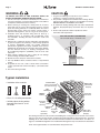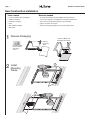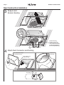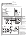
1
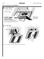
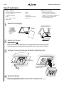
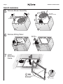
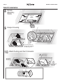
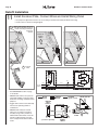
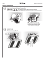
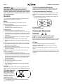
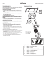
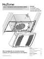
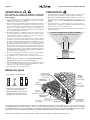
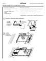
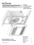
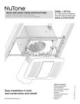
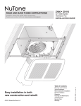
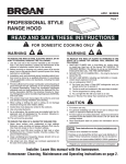
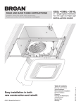
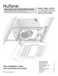
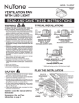
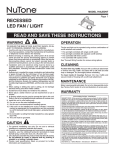
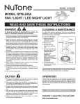
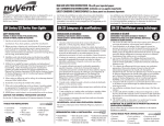
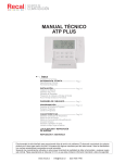
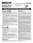
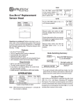
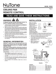
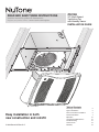
READ AND SAVE THESE INSTRUCTIONS
Installer: leave this guide with homeowner.
Register your product online at www.nutone.com/register.
ZN110H
X2 | Multi-Speed
Ventilation Fan
with Humidity Sensor
INSTALLATION GUIDE
Table of Contents
Easy installation in both
new construction and retrofit
© 2012 Broan-NuTone LLC
Warnings and Cautions
2
Typical Installation
2
New Construction Installation
3
Retrofit Installation
7
Operation12
Cleaning and Maintenance
12
Troubleshooting12
Service Parts
13
Warranty13
Page 2
ZN110H Installation Guide
WARNING
CAUTION
TO REDUCE THE RISK OF FIRE, ELECTRIC SHOCK, OR
INJURY TO PERSONS, OBSERVE THE FOLLOWING:
1. Use this unit only in the manner intended by the manufacturer.
If you have questions, contact the manufacturer at the address
or telephone number listed in the warranty.
2. Before servicing or cleaning unit, switch power off at service
panel and lock the service disconnecting means to prevent
power from being switched on accidentally. When the service
disconnecting means cannot be locked, securely fasten a
prominent warning device, such as a tag, to the service panel.
3.Installation work and electrical wiring must be done by a
qualified person(s) in accordance with all applicable codes
and standards, including fire-rated construction codes and
standards.
4. Sufficient air is needed for proper combustion and exhausting
of gases through the flue (chimney) of fuel burning equipment
to prevent backdrafting. Follow the heating equipment
manufacturer’s guideline and safety standards such as those
published by the National Fire Protection Association (NFPA),
and the American Society for Heating, Refrigeration and
Air Conditioning Engineers (ASHRAE), and the local code
authorities.
5.When cutting or drilling into wall or ceiling, do not damage
electrical wiring and other hidden utilities.
6. Ducted fans must always be vented to the outdoors.
7. Use only ON/OFF switch, mechanical timer or relay-switched
control.
8. Acceptable for use over a tub or shower when connected to
a GFCI (Ground Fault Circuit Interrupter) - protected branch
circuit.
9. This unit must be grounded.
1. For general ventilating use only. Do not use to exhaust
hazardous or explosive materials and vapors.
2. This product is designed for installation in flat ceilings. Sensor
will not function reliably if product is not installed in flat ceiling.
DO NOT MOUNT THIS PRODUCT IN A WALL.
3. To avoid motor bearing damage and noisy and/or unbalanced
impellers, keep drywall spray, construction dust, etc. off power
unit.
4. Please read specification label on product for further
information and requirements.
NOT FOR USE IN A COOKING AREA
Do not install above or inside this area
45°
45°
Cooking
Equipment
Floor
Typical Installation
• Installation is the same for:
INSULATION*
(Place around and
over Fan Housing.)
ROOF CAP*
(with built-in
damper)
FAN
HOUSING
Joists
I-Joists
Trusses
Keep duct
runs short.
POWER
CABLE*
• Fits in 2" x 8" ceiling construction.
• Infinitely adjust the fan position
between joists from 14" to 24"
on center.
Seal gaps
around
Housing.
ROUND
DUCT*
*Purchase
separately.
OR
Seal duct
joints with
tape.
ROUND
ELBOWS*
WALL CAP*
(with built-in
damper)
The ducting from this fan to the outside of the building has a strong effect on the air flow, noise and energy use of the fan. Use the shortest, straighest duct routing possible for best performance, and avoid
installing the fan with smaller ducts than recommended. Insulation around the ducts can reduce energy loss and inhibit mold growth. Fans installed with existing ducts may not achieve their rated airflow.
6-inch round rigid metal duct is recommended for best performance.
Page 3
ZN110H Installation Guide
New Construction Installation
Tools needed
Materials needed
• Power screwdriver with a Phillips bit
• Phillips screwdriver
• 6" round metal ducting recommended for best performance.
Use of other ducting is acceptable but may impact performance.
• Flathead screwdriver
• Roof cap or wall cap (built-in damper recommended)
•Pliers
• Tape to seal duct connections
• Wire insulation stripper
• Electrical wiring and supplies per local code requirements
• Wire cutter
1 Remove Packaging
Punch out Mask from
packaging. See Step 6.
Remove
Instruction
Sheet
Parts Bag holds
Knockout Plate
and six (6)
screws
2
2
Install
Mounting
Frame
1
4
3
Page 4
ZN110H Installation Guide
New Construction Installation
Snap-in and
3
Secure Housing
1
2
!
snap
4
Position Housing between joists and crimp channel on both sides of Mounting Frame to lock Housing in place.
Do not crimp Housing.
3 Screws from Parts Bag
4 Attach Duct Connector and Ducting
Top and bottom flanges
go outside Housing
2
Insert tab into slot
inside Housing
1
6" Ducting
3
Tape
Screw from
Parts Bag
Page 5
ZN110H Installation Guide
New Construction Installation
5 Connect Wires and Install Knockout Plate
• Run 120VAC electrical wiring to the installation location.
• Use proper UL-approved connectors to secure wiring to the Knockout Plate provided in Parts Bag.
• Connect wires as shown in wiring diagram.
1
Attach cable clamp to Knockout
Plate. Knockout Plate mounts to
outside of Housing and may be
oriented as desired.
3
2 Connect wires
4
Screw from
Parts Bag
120 VAC
LINE IN
GRD
GRD
WHT
WHT
BLK
BLK
• See OPERATION
section on page 12 for
details.
WHT
• MASTER switch
turns fan system on
and shuts it off for
fan cleaning and
maintenance purposes.
BLK
BLU
RED
MASTER
SENSOR/
CONTROL
MANUAL-ON
BRN
RED
14/4
(IF ALL
WALL SWITCH
OPTIONS
ARE USED)
FAN
BLK
SENSOR/
CONTROL
ORG
STANDARD OR MULTIFUNCTION WALL SWITCHES
BLACK
WHITE
MASTER
ON/OFF
SWITCH*
SENSOR
CONTROL
SWITCH*
RED
BLUE
MANUAL
ON
SWITCH*
ORANGE
BROWN
GROUND
(green or bare)
RECEPTACLES
SWITCH BOX
•SENSOR/CONTROL
switch turns humidity
control automatic
operation on/off.
• MANUAL-ON switch
directly increases fan
operation to certified
airflow rate.
• MASTER switch must be on for
humidity control or MANUAL-ON
switch to change fan operation to
certified airflow rate.
• MANUAL-ON switch is not required
to manually increase fan operation to
certified airflow rate (see page 10).
• MASTER and SENSOR/CONTROL
switches can be combined (see page
10).
KNOCKOUT
PLATE
* purchase separately
120 VAC
LINE IN
• MASTER switch along with or
separate from SENSOR/CONTROL
switch may be located where they
are not easily accessed for everyday
usage; they may need to be labeled
and located where they can’t be turned
on without being seen from fan to
comply with local and national codes.
Page 6
ZN110H Installation Guide
New Construction Installation
Insert Mask and
6
Finish Ceiling
• Install ceiling material.
• Cut out around Housing.
Mask protects unit
during construction.
Remove before
installing Grille.
CAUTION
IN ORDER TO PREVENT
MOTOR/CONTROL DAMAGE:
If the blower was unplugged, power must be
disconnected (see page 2, WARNING item 2)
before inserting motor plug into control assembly.
7 Install Grille
Plug in
Sensor
1
2
3
See Page 12 for Operations, Cleaning and Maintenance, and Troubleshooting.
Page 7
ZN110H Installation Guide
Retrofit Installation
Tools needed
Materials needed
• Power screwdriver with a Phillips bit
•Ruler
• Tape to seal duct connections
• Phillips screwdriver
•Pencil
• Flathead screwdriver
• Drywall saw
• Existing rigid duct will require the
addition of a short length of flexible duct
•Pliers
• Claw hammer or pry bar
• Wire insulation stripper
• Utility knife
• Electrical wiring and supplies per
local code requirements
• Wire cutter
1
Remove Packaging
Punch out Mask from
packaging. See Step 12.
Remove
Instruction
Sheet
Parts Bag holds
Knockout Plate
and six (6)
screws
Switch Off Power
2 WARNING
Before removing existing fan, switch power off at service panel and lock the service disconnecting
means to prevent power from being switched on accidentally. When the service disconnecting means
cannot be locked, securely fasten a prominent warning device, such as a tag, to the service panel.
3 Enlarge Ceiling Opening and Remove Existing Fan
12" (30.5 cm)
11" (27.9 cm)
parallel with joists
2
1
4
Existing ductwork and
wiring left in place
Examine Wiring
Examine the existing wiring to make sure it is not damaged. If any damage is found, DO NOT CONTINUE INSTALLATION of this product. Contact a qualified person(s) for repair.
Page 8
ZN110H Installation Guide
Retrofit Installation
5 Remove Blower Assembly
Set aside
Blower Assembly
1
2
Both sides
3
6 Remove Wiring Panel
Set aside
Wiring Panel
Set aside
screw
1
2
3
7
Insert
Mounting
Frame
4
3
5
1
Remove screws from
Mounting Frame
and set aside
2
Bend up
four tabs
Page 9
ZN110H Installation Guide
Retrofit Installation
Secure
8
Mounting
Frame
Screws set
aside
in Step 7
9
Snap-in Housing
2
!
snap
1
Pull existing wiring into
Housing as it is inserted
into Mounting Frame
10 Attach Ducting and Duct Connector
4
Screw from
Parts Bag
Pull existing
ductwork
into Housing
3
1
Insert tab into
slot inside
Housing
2
6" Ducting
Tape
Page 10
ZN110H Installation Guide
Retrofit Installation
11Install Knockout Plate, Connect Wires and Install Wiring Panel
• Use proper UL-approved connectors to secure wiring to the Knockout Plate provided in Parts Bag.
• Connect wires as shown in wiring diagram.
1
Attach cable clamp to Knockout
Plate. Knockout Plate mounts to
inside of Housing and may be
oriented as
desired.
Screw set
aside in
Step 6
2
5
Screw from
Parts Bag
6
4
3
Connect
wires
BLK
RED
MASTER
WALL
SWITCH
BLK
14/2
120 VAC
LINE IN
FAN
BLK
BLK
WHT
WHT
GRD
GRD
BRN SENSOR/
CONTROL
ORG
WHT
• See OPERATION section on page 12 for details.
• MASTER switch turns fan system on
along with humidity control and shuts them off for cleaning and maintenance purposes.
• Toggle mode can be used to manually increase fan operating airflow to
certified rate.
• MASTER switch may be located
where it is not easily accessed for
everyday usage; it may need to be
labeled and located where it can’t be
turned on without being seen from
fan to comply with local and national
codes.
BLACK
WHITE
MASTER
WALL
SWITCH*
ORANGE
BROWN
GROUND
(green or bare)
RECEPTACLES
SWITCH BOX
KNOCKOUT
PLATE
* purchase separately
120 VAC
LINE IN
Page 11
ZN110H Installation Guide
Retrofit Installation
and Secure Blower Assembly
12 Insert
CAUTION
IN ORDER TO PREVENT MOTOR/CONTROL DAMAGE:
Power must be disconnected (see page 2, WARNING item 2) before inserting motor plug into control assembly.
2
1
3 Screws from Parts Bag
If ceiling repairs are needed, place Mask in
Housing after Blower Assembly is secured.
See New Construction Installation Step 6.
Remove Mask before installing Grille.
13
Install Grille
Plug in
Sensor
1
1
2
2
3
Page 12
WARNING
Before servicing or cleaning unit,
switch power off at service panel and lock the service
disconnecting means to prevent power from being switched on
accidentally. When the service disconnecting means cannot be
locked, securely fasten a prominent warning device, such as a
tag, to the service panel.
Operation
It is normal for this ventilation fan to take approximately 5 seconds to start running after it is turned on.
ZN110H Installation Guide
To Set the User-Adjustable Airflow Rate*
Using a small, flat-blade screwdriver, carefully rotate the CFM
adjustment until the arrow points to the desired airflow rate.
To Set the User-Adjustable Time Delay*
Using a small, flat-blade screwdriver, carefully rotate the TIME
adjustment until arrow points to the desired minutes of time
delay.
* The user-adjustable controls are located in one corner of the
Fan Housing, behind the Grille.
Modes
(For reference, wiring diagrams are on pages 5 and 10.)
Continuous ventilation:
1. Turn master wall switch on (make sure any other wall
switches are off).
2. Fan operates at user-adjustable airflow rate.
Humidity sensing:
1. If master wall switch is not already on, turn it on.
2. Turn sensor/control wall switch on (make sure any other wall
switches are off). Some installations may not have a separate
sensor/control wall switch; where it is combined with master
wall switch.
3. Sensor monitors humidity level for (a) moderate to rapid rise
or (b) above set-point.
4. Fan operates at certified airflow rate to reduce humidity.
5. When humidity decreases, fan enters time delay mode. (See
below.)
Manual-on (optional manual-on wall switch must be installed):
1. Turn master and manual-on wall switches on (sensor/control
wall switch can be on or off).
2. Fan operates at certified airflow rate.
3. When manual-on wall switch is turned off, fan enters timedoff mode. (See below.)
Toggle (for manual operation when optional manual-on wall
switch is not installed):
1. If master wall switch is not already on, turn it on.
2. Turn sensor/control wall switch on (make sure any other wall
switches are off). Some installations may not have a separate
sensor/control wall switch; where it is combined with master
wall switch then turn master wall switch on and off using
following instructions.
3. Wait at least one-second.
4. Turn switch off for less than one-second.
5. Turn switch back on.
6. Fan will operate at certified airflow rate and enter time delay
mode. (See next.)
Time Delay:
Fan operates at certified airflow rate until user-adjustable TIME
delay has passed, then fan reverts to user-adjustable airflow rate.
To Set User-Adjustable
Humidity Sensitivity**
Using a small, flat-blade
screwdriver, carefully rotate
HUMIDITY adjustment until
arrow points to desired
humidity level shown in
percent relative humidity (%RH).
** User-adjustable humidity sensitivity is located in corner of
Fan Housing behind Grille.
To Turn Fan OFF
Turn the master switch OFF.
Cleaning and Maintenance
CAUTION
IN ORDER TO PREVENT MOTOR/CONTROL DAMAGE:
DO NOT remove motor plug to stop spinning motor.
Power must be disconnected (see WARNING at top left of this page)
before motor plug is removed or inserted into control assembly.
To Clean
For quiet and efficient operation, long life and attractive
appearance, remove Grille and vacuum interior of unit with a
dusting brush attachment.
Do not use cleaning sprays, solvents or water on, or near, the
sensor.
Motor is permanently lubricated and never needs oiling. If motor
is making excessive or unusual noises, replace Control Assembly
and Motor.
Page 13
Troubleshooting
Before continuing, turn off power as previously noted in WARNING
and CAUTION sections on the previous page.
Symptom: Fan does not run.
• Check for an open fuse or circuit breaker in building’s service
panel.
• Check two (2) plug-in connections for Motor and its Control are
seated firmly in place.
• Check two (2) plug-in connections for Sensor and its Control
are seated firmly in place.
• Check that Blower Wheel spins freely.
Symptom: Humidity mode does not operate fan at certified air
flow rate.
• Check two (2) plug-in connections for Sensor and its Control
are seated firmly in place.
Symptom: Fan runs erratically.
• Check that Blower Wheel is firmly attached to Motor shaft and
both spin freely.
Symptom: Fan seems noisy.
• Check that back draft damper in fan’s Duct Connector pivots
freely. Screws used to attach duct to Duct Connector may
prevent damper from opening.
• Check that back draft damper in wall or roof cap pivots freely.
Dampers are sometimes mistakenly painted shut or obstructed
by bird or insect debris.
Symptom: Fan does not properly ventilate room.
• For spot ventilation, turn both master switch and sensor/control
wall switch ON, so sensor/control operates fan at certified
airflow rate.
• For spot ventilation followed by continuous ventilation, increase
the “TIME” setting of user-adjustable time delay.
• For continuous ventilation, increase “CFM” setting of useradjustable airflow rate.
ZN110H Installation Guide
Service Parts
1
2
3
4
7
6
8
Order replacement
parts by Part No.,
not by Key No.
9
10
5
Key No. Part No.
Description
1
97018349 Mounting Frame
2
97018721 Knockout Plate & Screws
3 97018382Housing
4
97018472 Wiring Panel/Harness Assembly
5
97019010 Humidity Control Assembly & Grille Assembly (includes Key No. 10)
6
97018753 Control Assembly & Motor
7
97018331 Duct Connector
8
99020301 Blower Wheel
9
97018768 Scroll Assembly
10
99140208 Grille Spring (2 req’d)
Page 14
ZN110H Installation Guide
Warranty
NuTone Ventilation Fans Limited Warranty
WARRANTY PERIOD: NuTone warrants to the original consumer purchaser of
its NuTone Ventilation Fans (the “Fan”) that your Fan will be materially free from
defects in materials or workmanship for a period of three (3) years from the date
of original purchase. This warranty does not cover accessories, such as speed
controls, that may be purchased separately and installed with the Fan.
The limited warranty period for replacement parts, and for Fans repaired or
replaced under this limited warranty, shall continue for the remainder of the
original warranty period.
NO OTHER WARRANTIES: THE FOREGOING WARRANTIES ARE
EXCLUSIVE AND IN LIEU OF ANY OTHER WARRANTIES, EXPRESS OR
IMPLIED. NUTONE DISCLAIMS AND EXCLUDES ALL OTHER EXPRESS
WARRANTIES, AND DISCLAIMS AND EXCLUDES ALL WARRANTIES
IMPLIED BY LAW, INCLUDING WITHOUT LIMITATION THOSE OF
MERCHANTABILITY AND FITNESS FOR A PARTICULAR PURPOSE. TO
THE EXTENT THAT APPLICABLE LAW PROHIBITS THE EXCLUSION OF
IMPLIED WARRANTIES, THE DURATION OF ANY APPLICABLE IMPLIED
WARRANTY IS LIMITED TO THE PERIOD SPECIFIED FOR THE EXPRESS
WARRANTY. Some states do not allow limitations on how long an implied
warranty lasts, so the above limitation may not apply to you. Any oral or written
description of the Fan is for the sole purpose of identifying it and shall not be
construed as an express warranty.
REMEDY: During the applicable limited warranty period, NuTone will, at its
option, provide replacement parts for, or repair or replace, without charge,
any Fan or part thereof, to the extent NuTone finds it to be covered by and in
breach of this limited warranty. NuTone will ship the repaired or replaced Fan
or replacement parts to you at no charge. You are responsible for all costs for
removal, reinstallation and shipping, insurance or other freight charges incurred
in the shipment of the Fan or part to NuTone. This warranty does not cover (a)
normal maintenance and service, (b) normal wear and tear, (c) any Fans or
parts which have been subject to misuse, abuse, abnormal usage, negligence,
accident, improper or insufficient maintenance, storage or repair (other than
repair by NuTone), (d) damage caused by faulty installation, or installation or
use contrary to recommendations or instructions, (e) any Fan that has been
moved from its original point of installation, (f) damage caused by environmental
or natural elements, (g) damage in transit, (h) natural wear of finish, (i) Fans in
commercial or nonresidential use, or (j) damage caused by fire, flood or other
act of God. This warranty covers only Fans sold in the United States or through
U.S. distributors authorized by NuTone.
EXCLUSION OF DAMAGES: NUTONE’S OBLIGATION TO PROVIDE
REPLACEMENT PARTS, OR REPAIR OR REPLACE, AT NUTONE’S
OPTION, SHALL BE YOUR SOLE AND EXCLUSIVE REMEDY UNDER
THIS LIMITED WARRANTY AND NUTONE’S SOLE AND EXCLUSIVE
OBLIGATION. NUTONE SHALL NOT BE LIABLE FOR INCIDENTAL,
INDIRECT, CONSEQUENTIAL OR SPECIAL DAMAGES ARISING OUT
OF OR IN CONNECTION WITH THE FAN, ITS USE OR PERFORMANCE.
Incidental damages include but are not limited to such damages as loss of time
and loss of use. Consequential damages include but are not limited to the cost
of repairing or replacing other property which was damaged if the Fan does not
work properly.
Some states do not allow the exclusion or limitation of incidental or
consequential damages, so the above limitation or exclusion may not apply to
you. This warranty gives you specific legal rights, and you may also have other
rights, which vary from state to state.
This warranty supersedes all prior warranties and is not transferable from the
original consumer purchaser.
NUTONE SHALL NOT BE LIABLE TO YOU, OR TO ANYONE CLAIMING
UNDER YOU, FOR ANY OTHER OBLIGATIONS OR LIABILITIES,
INCLUDING, BUT NOT LIMITED TO, OBLIGATIONS OR LIABILITIES
ARISING OUT OF BREACH OF CONTRACT OR WARRANTY, NEGLIGENCE
OR OTHER TORT OR ANY THEORY OF STRICT LIABILITY, WITH RESPECT
TO THE FAN OR NUTONE’S ACTS OR OMISSIONS OR OTHERWISE.
This warranty covers only replacement or repair of defective Fans or parts
thereof at NuTone’s main facility and does not include the cost of field service
travel and living expenses.
Any assistance NuTone provides to or procures for you outside the terms,
limitations or exclusions of this limited warranty will not constitute a waiver of
such terms, limitations or exclusions, nor will such assistance extend or revive
the warranty.
NuTone will not reimburse you for any expenses incurred by you in repairing or
replacing any defective Fan, except for those incurred with NuTone’s prior written
permission.
HOW TO OBTAIN WARRANTY SERVICE: To qualify for warranty service, you
must (a) notify NuTone at the address or telephone number stated below within
seven (7) days of discovering the covered defect, (b) give the model number
and part identification and (c) describe the nature of any defect in the Fan or
part. At the time of requesting warranty service, you must present evidence of
the original purchase date.
Broan-NuTone LLC, 926 West State Street, Hartford, WI 53027
(1-888-336-6151)
www.nutone.com
If you must send the Fan or part to NuTone, as instructed by NuTone, you must
properly pack the Fan or part—NuTone is not responsible for damage in transit.
99045124C
LEA Y CONSERVE ESTAS INSTRUCCIONES
Aviso al instalador: Deje esta guía con el dueño de la casa.
Registre su producto en línea en www.nutone.com/register.
ZN110H
X2 | Ventilador
de velocidad múltiple
con sensor de humedad
GUÍA DE INSTALACIÓN
Índice
Fácil instalación en construcciones
nuevas y en aplicaciones de conversión
© 2012 Broan-NuTone LLC
Advertencias y precauciones
16
Instalación típica 16
Instalación en una construcción nueva 17
Instalación de conversión 21
Funcionamiento 26
Limpieza y mantenimiento 26
Resolución de problemas 26
Piezas de servicio 27
Garantía27
Página 16
Guía de instalación del ventilador ZN110H
ADVERTENCIA
PRECAUCIÓN
PARA REDUCIR EL RIESGO DE INCENDIOS, DESCARGAS
ELÉCTRICAS O LESIONES PERSONALES, OBSERVE LAS SIGUIENTES
PRECAUCIONES:
1. Use la unidad solo de la manera indicada por el fabricante. Si tiene
preguntas, comuníquese con el fabricante a la dirección o al número
telefónico que se incluye en la garantía.
2. Antes de dar servicio a la unidad o de limpiarla, interrumpa el suministro
eléctrico en el panel de servicio y bloquee los medios de desconexión
del servicio para evitar que la electricidad se reanude accidentalmente.
Cuando no sea posible bloquear los medios de desconexión del
servicio, fije firmemente una señal de advertencia (como una etiqueta)
en un lugar visible del panel de servicio.
3. El trabajo de instalación y el cableado eléctrico deben estar a cargo de
un personal capacitado, de acuerdo con todos los códigos y normas
correspondientes, incluidos los códigos y normas de construcción
específicos sobre protección contra incendios.
4. Es necesario que haya suficiente aire para que se lleve a cabo una
combustión y una extracción adecuadas de los gases a través del tubo
de humos (chimenea) del equipo quemador de combustible, con el fin
de evitar el contratiro. Siga las directrices y las normas de seguridad
del fabricante del equipo de calefacción, como las publicadas por la
Asociación Nacional de Protección contra Incendios (National Fire
Protection Association, NFPA), la Sociedad Americana de Ingenieros
de Calefacción, Refrigeración y Aire Acondicionado (American Society
for Heating, Refrigeration and Air Conditioning Engineers, ASHRAE) y
las autoridades de los códigos locales.
5. Al cortar o perforar a través de la pared o del cielo raso, tenga cuidado
de no dañar el cableado eléctrico ni otros servicios ocultos.
6. Los ventiladores con conductos siempre se deben conectar hacia el
exterior.
1. Solo para usarse como medio de ventilación general. No debe usarse
para la extracción de materiales o vapores peligrosos o explosivos.
2. Este producto está diseñado para instalarse solamente en un cielo raso
plano. El sensor no funcionará de forma fiable si el producto no se
instala en un cielo raso plano. NO MONTE ESTE PRODUCTO EN LA
PARED.
3. Para evitar daños a los cojinetes del motor y rotores ruidosos o
desbalanceados, mantenga la unidad de potencia protegida contra
rociados de yeso, polvos de construcción, etc.
4. Lea la etiqueta de especificaciones del producto para ver información y
requisitos adicionales.
NO USAR EL PRODUCTO EN UN ÁREA DE COCINA
No instale el equipo sobre o dentro de esta área.
45°
45°
Equipo
de cocina
Piso
7. Use solamente un interruptor de ENCENDIDO/APAGADO, un
temporizador mecánico o un control de relé-interruptor.
8. Esta unidad puede instalarse sobre una tina o ducha siempre que se
conecte a un GFCI (interruptor accionado por pérdida de conexión
a tierra) en un circuito de derivación protegido.
9. Esta unidad debe estar conectada a tierra.
Instalación típica
• La instalación es la misma para:
AISLAMIENTO*
(Colóquelo alrededor
y sobre la cubierta
del ventilador).
TAPA DE
TECHO*
(con regulador
de tiro integrado)
CUBIERTA DEL
VENTILADOR
CABLE
ELÉCTRICO*
Vigas
Vigas en “I”
Mantenga
cortos los tramos
de conductos.
Cerchas
• Cabe en una construcción de cielo
raso de 2 x 8 pulg. (5 x 20 cm)
• Ajustes ilimitados de la posición del
ventilador entre las vigas de 14 a
24 pulg. (35.5 a 61 cm) en el centro.
Selle las
separaciones
alrededor de la cubierta.
O
CONDUCTO
REDONDO*
Selle con
cinta las uniones CODOS
*Se compra
por separado. de los conductos. REDONDOS*
TAPA DE PARED*
(con regulador
de tiro integrado)
Los conductos desde este ventilador hacia el exterior del edificio tienen un gran efecto sobre el flujo de aire, el ruido y el uso de energía
del ventilador. Utilice el tramo de conductos más corto y recto posible para obtener un desempeño óptimo y evite instalar el ventilador
con conductos menores que los recomendados. El aislamiento alrededor de los conductos puede reducir la pérdida de energía e inhibir
el desarrollo de moho. Los ventiladores instalados en conductos existentes podrían no obtener el flujo de aire nominal.
Para un mejor desempeño, se recomienda utilizar conductos metálicos redondos y rígidos de 6 pulg. (15.2 cm).
Página 17
Guía de instalación del ventilador ZN110H
Instalación en una construcción nueva
Herramientas necesarias
Materiales necesarios
• Destornillador eléctrico con cabeza Phillips
•Se recomienda utilizar conductos metálicos redondos de 6 pulg. (15.2 cm)
para obtener un desempeño óptimo. Aunque el uso de otros sistemas de
conductos es aceptable, puede afectar al desempeño.
• Destornillador Phillips
• Destornillador de cabeza plana
•Tapa de techo o tapa de pared (se recomienda que tenga regulador
de tiro integrado)
•Alicates
• Desforrador de cables
• Cinta para sellar las conexiones de los conductos
• Cortador de cables
• Cableado eléctrico y suministros según los requisitos de los códigos locales
1 Saque el producto de su empaque
Retire la cubierta protectora del
empaque. Proceda con el paso 6.
Saque la hoja
de instrucciones
La bolsa de piezas
contiene la placa
de agujero ciego y
seis (6) tornillos
2
2
Instale
el marco
de montaje
1
4
3
Página 18
Guía de instalación del ventilador ZN110H
Instalación en una construcción nueva
y
3Afijecople
la cubierta
1
2
le
Acopesión
a pr
4
Coloque la cubierta entre
las vigas y doble el canal
a ambos lados del marco
de montaje para fijar la
cubierta en su lugar.
No doble la cubierta.
3 Tornillos de la bolsa de piezas
4 Acople el conector de conducto y los conductos
Las bridas superior e inferior se
instalan por fuera de la cubierta
Introduzca la pestaña
en la ranura del interior
de la cubierta
1
Conductos de
6 pulg. (15.2 cm)
3
Cinta
2
Tornillo
de la bolsa
de piezas
Página 19
Guía de instalación del ventilador ZN110H
Instalación en una construcción nueva
5 Conecte los cables e instale la placa de agujero ciego
• Tienda el cable eléctrico de 120 VCA hasta el lugar de la instalación.
•Use conectores aprobados por UL para fijar el cableado a la placa de agujero ciego incluida en la bolsa de piezas.
• Conecte los cables tal como se ilustra en el diagrama de cableado.
1
• Vea los detalles
de la sección
FUNCIONAMIENTO
en la página 26.
Acople la abrazadera para cables
a la placa de agujero ciego.
La placa de agujero ciego se
monta en el exterior de la cubierta
y puede orientarse en la dirección
que se desee.
3
2 Conecte los cables
4
Tornillo
de la bolsa
de piezas
TIERRA
120 VCA
LÍNEA DE BLANCO
ENTRADA
NEGRO
TIERRA
BLANCO
BLANCO
NEGRO
NEGRO
AZUL
ROJO
INTERRUPTOR
MAESTRO
SENSOR/
CONTROL
CAFÉ
ROJO
14/4
(SI SE UTILIZAN
ENCENDIDO TODAS LAS OPCIONES
DE INTERRUPTORES
MANUAL
DE PARED)
VENTILADOR
NEGRO
SENSOR/
CONTROL
NARANJA
INTERRUPTORES DE PARED
MULTIFUNCIONALES O ESTÁNDAR
NEGRO
BLANCO
ROJO
AZUL
ANARANJADO
MARRÓN
RECEPTÁCULOS
TIERRA
INTERRUPTOR
(Verde o sin aislamiento)
MAESTRO DE INTERRUPTOR INTERRUPTOR
CAJA DEL
ENCENDIDO/ DE CONTROL DE ENCENDIDO
INTERRUPTOR
APAGADO* DEL SENSOR*
MANUAL*
PLACA DE
AGUJERO CIEGO
* Se compra por separado
LÍNEA DE
ENTRADA DE 120 VCA
• El interruptor
MAESTRO enciende
y apaga el sistema
del ventilador para
fines de limpieza y
mantenimiento.
• El interruptor del
SENSOR/CONTROL
enciende/apaga
el funcionamiento
automático del control
de humedad.
• El interruptor de
ENCENDIDO MANUAL
aumenta directamente
el funcionamiento del
ventilador a un índice
certificada de flujo de
aire.
• El interruptor
MAESTRO debe estar
encendido para el
control de humedad
o en interruptor
de ENCENDIDO
MANUAL para cambiar
el funcionamiento
del ventilador a un
certificada flujo de aire.
• El interruptor de ENCENDIDO
MANUAL aumenta directamente el
funcionamiento del ventilador a un
índice certificado de flujo de aire (vea
la página 24).
• Se pueden combinar los interruptores
MAESTRO y SENSOR/CONTROL
(vea la página 24).
• El interruptor MAESTRO, junto o por
separado del interruptor SENSOR/
CONTROL, se puede colocar donde
no se pueda tener acceso fácilmente
para uso diario; tal vez sea necesario
etiquetarlo y situarlo donde no se
pueda encender sin ser visto desde
el ventilador para cumplir con los
códigos locales y nacionales.
Página 20
Guía de instalación del ventilador ZN110H
Instalación en una construcción nueva
Inserte la cubierta
6
protectora y finalice
el cielo raso
•Instale el material del cielo raso.
•Recorte alrededor de la cubierta.
PRECAUCIÓN
La cubierta protege
la unidad durante la
construcción. Retírela
antes de instalar la rejilla.
PARA PREVENIR DAÑOS EN
EL MOTOR/CONTROL:
Si el motor estaba desconectado, se debe
desconectar la electricidad (vea la página 16,
ADVERTENCIA, punto 2) antes de insertar el
enchufe del motor en el conjunto de control.
7 Instale la rejilla
Conecte
el sensor
1
2
3
Consulte la página 26 para obtener información sobre el funcionamiento, limpieza, mantenimiento y resolución de problemas.
Página 21
Guía de instalación del ventilador ZN110H
Instalación de conversión
Herramientas necesarias
Materiales necesarios
•Destornillador eléctrico con cabeza Phillips
•Regla
•Cinta para sellar las conexiones
de los conductos
• Destornillador Phillips
•Lápiz
• Destornillador de cabeza plana
• Sierra para panel de yeso
•Alicates
• Martillo de uñas o pata de cabra
• Desforrador de cables
• Navaja utilitaria
•Los conductos rígidos existentes
requerirán la adición de un tramo corto
de conducto flexible
•Cableado eléctrico y suministros según
los requisitos de los códigos locales
• Cortador de cables
1
Saque el producto de su empaque
Retire la cubierta protectora del
empaque. Proceda con el paso 12.
Saque la hoja
de instrucciones
La bolsa de piezas
contiene la placa
de agujero ciego y
seis (6) tornillos
Apague la unidad
2 ADVERTENCIA
Antes de quitar la unidad existente, interrumpa el suministro eléctrico en el panel de servicio y bloquee los
medios de desconexión del servicio para evitar que la electricidad se reanude accidentalmente. Cuando
no sea posible bloquear los medios de desconexión del servicio, fije firmemente una señal de advertencia
(como una etiqueta) en un lugar visible del panel de servicio.
3 Agrande la abertura del cielo raso y retire el ventilador existente
1212"
pulg.
(30.5
cm)
(30.5
cm)
11 pulg. (27.9 cm)
paralelo a las vigas
2
1
4
Conductos existentes
y cableado en su lugar
Examine el cableado
Examine el cableado existente para asegurarse de que no esté dañado. Si encuentra algún daño,
NO CONTINÚE CON LA INSTALACIÓN de este producto. Encargue la reparación a personas
debidamente capacitadas.
Página 22
Guía de instalación del ventilador ZN110H
Instalación de conversión
5 Retire el conjunto del ventilador
Ponga a un lado el
conjunto del ventilador
1
2
Ambos lados
3
6 Retire el panel de cableado
Ponga a un lado el
panel de cableado
Ponga a un
lado el tornillo
1
2
3
7
Inserte
el marco
de montaje
4
3
5
1
Saque los tornillos
del marco de montaje
y póngalos a un lado
2
Doble hacia arriba
las cuatro pestañas
Página 23
Guía de instalación del ventilador ZN110H
Instalación de conversión
el marco
8Sujete
de montaje
Tornillos
extraídos en el
paso 7
9
Encaje la cubierta a presión
2
le
Acopesión
r
p
a
1
Tire del cableado existente hacia el
interior de la cubierta a medida que
lo inserta en el marco de montaje
10 Acople el conector de conductos y los conductos
4
Tire de los
conductos
existentes
hacia el
interior
de la
cubierta
Tornillo de la
bolsa de piezas
3
1
2
Conductos de
6 pulg. (15.2 cm)
Cinta
Introduzca la
pestaña en la
ranura del interior
de la cubierta
Página 24
Guía de instalación del ventilador ZN110H
Instalación de conversión
la placa de agujero ciego, conecte los cables e instale
11Instale
el panel de cableado
•Use conectores aprobados por UL para fijar el cableado a la placa de agujero ciego incluida en la bolsa de piezas.
• Conecte los cables tal como se ilustra en el diagrama de cableado.
Acople la abrazadera para cables
a la placa de agujero ciego.
La placa de agujero ciego se
monta en el
interior de
la cubierta
y puede
orientarse en la
dirección que
2
se desee.
Tornillo
1
Tornillo
extraído en el
paso 6
5
de la bolsa
de piezas
6
4
3
Conecte
los cables
NEGRO
ROJO
INTERRUPTOR
DE PARED
MAESTRO
VENTILADOR
NEGRO
14/2
NEGRO
CAFÉ
NEGRO
120 VCA
BLANCO
LÍNEA DE
ENTRADA TIERRA
SENSOR/
CONTROL
NARANJA
BLANCO
TIERRA
BLANCO
• Vea los detalles de la sección
FUNCIONAMIENTO en la página 26.
• El interruptor MAESTRO enciendala
el sistema de ventilador junto con el
control de humedad, y los apaga para
fines de limpieza y mantenimiento.
• Se puede usar el modo alterno para
aumentar manualmente el flujo de
aire de funcionamiento del ventilador
a un nivel certificado.
• El interruptor MAESTRO se puede
colocar donde no se pueda tener
acceso fácilmente para uso diario;
tal vez sea necesario etiquetarlo
y colocarlo donde no se pueda
encender sin ser visto desde el
ventilador para cumplir con los
códigos locales y nacionales.
NEGRO
BLANCO
ANARANJADO
MARRÓN
INTERRUPTOR
DE PARED
MAESTRO*
TIERRA
(Verde o sin
aislamiento)
RECEPTÁCULOS
CAJA DEL
INTERRUPTOR
PLACA DE
AGUJERO CIEGO
* Se compra por separado
LÍNEA DE
ENTRADA DE 120 VCA
Página 25
Guía de instalación del ventilador ZN110H
Instalación de conversión
y fije el conjunto del ventilador
12 Inserte
PRECAUCIÓN
PARA PREVENIR DAÑOS EN EL MOTOR/CONTROL:
Debe desconectar la electricidad (vea la página 16, ADVERTENCIA, punto 2) antes de insertar el enchufe
del motor en el conjunto de control.
2
1
3 Tornillos de la bolsa de piezas
Si es necesario realizar reparaciones en
el cielo raso, coloque el protector en la
cubierta después de haber fijado el conjunto
del ventilador. Consulte el paso 6 sobre la
instalación en una construcción nueva. Retire la
cubierta protectora antes de instalar la rejilla.
13 Instale la rejilla
Conecte
el sensor
1
1
2
2
3
Página 26
ADVERTENCIA
Antes de dar servicio a la unidad o de
limpiarla, interrumpa el suministro eléctrico en el panel de servicio y bloquee
los medios de desconexión del servicio para evitar que la electricidad se
reanude accidentalmente. Cuando no sea posible bloquear los medios de
desconexión del servicio, fije firmemente una señal de advertencia (como una
etiqueta) en un lugar visible del panel de servicio.
Funcionamiento
Es normal que este ventilador para tomar aproximadamente 5 segundos para empezar
a correr después de que se encienda.
Modos
Guía de instalación del ventilador ZN110H
Cómo ajustar el índice de flujo de aire ajustable por el
usuario*
Utilizando un destornillador pequeño de cabeza plana, gire con cuidado el control
de ajuste CFM (pies cúbicos por minuto) hasta que la flecha apunte al índice
de flujo de aire deseado.
Cómo ajustar el tiempo de espera ajustable por el
usuario*
Utilizando un destornillador pequeño de cabeza plana, gire con cuidado el control
de ajuste del TIEMPO hasta que la flecha apunte al tiempo de espera deseado,
expresado en minutos.
* Los controles ajustables por el usuario están situados en una esquina de la
cubierta del ventilador, detrás de la rejilla.
(Como referencia, los diagramas de cableado se encuentran en las páginas 19 y
24).
Ventilación continua:
1. Encienda el interruptor de pared maestro (asegúrese de que todos los demás
interruptores de pared están apagados).
2. El ventilador funciona a un índice nominal de flujo de aire ajustable por el usuario.
Detección de humedad:
1. Si el interruptor de pared maestro todavía no está encendido, enciéndalo.
2. Encienda el interruptor de pared del sensor/control (asegúrese de que todos
los demás interruptores de pared están apagados). Es posible que algunas
instalaciones no dispongan de un interruptor de pared independiente para el
sensor/control, y que este interruptor esté combinado con un interruptor
de pared maestro.
3. El sensor controla el nivel de humedad en caso de que se produzca un (a)
ascenso de moderado a rápido o (b) si sobrepasa un nivel preestablecido.
4. El ventilador funciona a un índice certificada de flujo de aire para reducir
la humedad.
5. Cuando la humedad disminuye, el ventilador entra en el modo de retardo de
tiempo. (Vea más abajo.)
Encendido manual (se debe instalar un interruptor de pared opcional para el
encendido manual):
1. Encienda los interruptores de pared principal y de encendido manual (el
interruptor de pared del sensor/control puede estar encendido o apagado).
2. El ventilador funciona a un índice certificada de flujo de aire.
3. Cuando el interruptor de pared de encendido manual está apagado,
el ventilador pasa al modo de retardo de tiempo. (Vea más abajo.)
Alternar entre encendido y apagado (para la operación manual cuando el
interruptor de pared opcional para el encendido manual no esté instalado):
1. Si el interruptor de pared maestro todavía no está encendido, enciéndalo.
2. Encienda el interruptor de pared del sensor/control (asegúrese de que todos
los demás interruptores de pared están apagados). Es posible que algunas
instalaciones no dispongan de un interruptor de pared independiente para
el sensor/control; en los casos en que este interruptor esté combinado con
un interruptor de pared maestro, encienda y apague el interruptor de pared
maestro siguiendo las instrucciones a continuación.
3. Espere al menos 1 segundo.
4. Apague el interruptor de alimentación durante al menos de 1 segundo.
5. Vuelva a encender el interruptor.
6. El ventilador funcionará a una velocidad certificada de flujo de aire y entrará
en el modo de retardo de tiempo. (Vea a continuación.)
Retardo de tiempo:
El ventilador continúa funcionando a una velocidad certificada de flujo de aire
hasta que haya pasado por el usuario ajustable retardo de tiempo, y luego se
vuelve fan de cuadal de aire velocidad ajustable por el usuario.
Cómo configurar el nivel
de sensibilidad a la
humedad ajustable por el
usuario**
Usando un destornillador pequeño
de cabeza plana, gire con cuidado
el control de ajuste de la humedad
hasta que la flecha apunte al nivel de
humedad deseado, expresado en porcentajes de humedad relativa (%RH).
**El control del sensor de humedad ajustable por el usuario está situado en la
esquina de la cubierta del ventilador, detrás de la rejilla.
Para APAGAR el ventilador
APAGUE el interruptor maestro.
Limpieza y mantenimiento
PRECAUCIÓN
PARA PREVENIR DAÑOS EN EL MOTOR/CONTROL:
NO retire el enchufe del motor para detener el giro del motor.
La electricidad debe estar desconectada (vea la ADVERTENCIA en la parte superior
izquierda de esta página) antes de retirar o insertar el enchufe del motor en el
conjunto de control.
Para limpiarlo
Para lograr un funcionamiento silencioso y eficiente, además de una larga vida
útil y una apariencia atractiva, retire la rejilla y aspire el interior de la unidad con
un accesorio del cepillo para quitar el polvo.
No use sprays limpiadores, solventes ni agua en el sensor o cerca del mismo.
El motor está permanentemente lubricado y nunca necesitará aceite. Si el motor
hace ruidos excesivos o inusuales, reemplace el conjunto de control y el motor.
Página 27
Guía de instalación del ventilador ZN110H
Resolución de problemas
Piezas de servicio
Antes de continuar, desconecte la electricidad, como se señaló en las secciones
ADVERTENCIA y PRECAUCIÓN de la página anterior.
1
Síntoma: El ventilador no funciona.
• Compruebe si hay un fusible o un interruptor automático abierto en el panel
de servicio del edificio.
• Asegúrese de que los dos (2) conectores de enchufe del motor y de su
control estén bien afianzados en su lugar.
• Asegúrese de que los dos (2) conectores de enchufe del sensor y de su
control estén bien afianzados en su lugar.
• Compruebe que la rueda del ventilador gire sin obstrucciones.
2
3
Síntoma: El modo de humedad no hace funcionar el ventilador al índice
nominal de flujo de aire.
• Asegúrese de que los dos (2) conectores de enchufe del sensor y de su
control estén bien afianzados en su lugar.
Síntoma: El ventilador funciona de forma errática.
• Compruebe que la rueda del ventilador esté firmemente acoplada al eje
del motor y que ambos giren sin obstrucciones.
4
Síntoma: El ventilador hace demasiado ruido.
• Compruebe que el regulador de tiro invertido del conector de conductos del
ventilador gire sin obstrucciones. Los tornillos utilizados para afianzar el
conducto al conector de conductos pueden impedir que el regulador de tiro se
abra.
• Compruebe que el regulador de tiro invertido del conector de conductos de
la tapa de techo o de pared gire sin obstrucciones. Estos reguladores suelen
cerrarse accidentalmente después de ser pintados o suelen obstruirse con
pájaros o restos de insectos.
7
6
Síntoma: El ventilador no ventila adecuadamente la habitación.
• Para ventilar un área específica, ENCIENDA tanto el interruptor maestro como
el interruptor de pared del sensor/control, para que el sensor/control haga
funcionar al índice nominal de flujo de aire.
• Para ventilar un área específica seguida de ventilación continua, aumente el
nivel de “TIME” (Tiempo) del selector de tiempo de espera ajustable por el
usuario.
• Para una ventilación continua aumente el nivel de “CFM” correspondiente al
índice nominal de flujo de aire ajustable por el usuario.
8
Pida las piezas por
número de pieza, no
por número de clave.
9
10
5
N.º de clave N.º de pieza Descripción
1
2
3
4
97018349 Marco de montaje
97018721 Placa de agujero ciego y tornillos
97018382 Cubierta
97018472 Conjunto del panel de cableado/
mazo de cables
5
97019010 Conjunto de control de humedad y
Conjunto de la rejilla (incluye 10)
6
97018753 Conjunto de control y motor
7
97018331 Conector del conducto
8
99020301 Rueda del ventilador
9
97018768 Conjunto del desplazador
10
99140208 Resorte de la rejilla (se requieren 2)
Página 28
Guía de instalación del ventilador ZN110H
Garantía
Garantía limitada para los ventiladores para ventilación NuTone
PERÍODO DE LA GARANTÍA: NuTone le garantiza al comprador consumidor original
de los Ventiladores para ventilación NuTone (el “Ventilador”) que su ventilador no
presentará defectos de material o de mano de obra durante un período de tres (3) años
a partir de la fecha de la compra original. Esta garantía no cubre accesorios tales
como controles de velocidad que pueden adquirirse por separado y que se instalan
con el Ventilador.
El período de garantía limitada para los repuestos y para los Ventiladores reparados o
reemplazados bajo esta garantía limitada continuará durante el período restante de la
garantía original.
AUSENCIA DE OTRAS GARANTÍAS: LAS SIGUIENTES GARANTÍAS SON
EXCLUSIVAS Y SE RELACIONAN CON TODA OTRA GARANTÍA EXPRESA
O IMPLÍCITA. NUTONE RENUNCIA Y EXCLUYE TODA OTRA GARANTÍA
EXPRESA Y RENUNCIA Y EXCLUYE TODA GARANTÍA QUE EXIJA LA LEY,
INCLUYENDO PERO NO LIMITÁNDOSE A AQUELLAS RELACIONADAS CON LA
COMERCIABILIDAD Y LA APTITUD PARA UN FIN EN PARTICULAR. EN TANTO
LA LEY CORRESPONDIENTE PROHÍBA LA EXCLUSIÓN DE LAS GARANTÍAS
IMPLÍCITAS, LA DURACIÓN DE TODA GARANTÍA IMPLÍCITA APLICABLE SE
LIMITA AL PERÍODO ESPECIFICADO PARA LA GARANTÍA EXPRESA. Algunos
estados no permiten limitaciones sobre cuál es la duración de una garantía implícita,
de modo que la limitación antes mencionada puede no aplicarse a su caso. Toda
descripción escrita u oral del Ventilador es al sólo fin de identificarlo y no deberá
tomarse como una garantía expresa.
COMPENSACIÓN: Durante el transcurso del período aplicable de la garantía limitada,
NuTone, a su discreción, proporcionará repuestos, reparación o reemplazo, en forma
gratuita, para cualquier Ventilador o cualquiera de sus piezas, en tanto NuTone
considere que está cubierto por y en violación de esta garantía limitada. NuTone le
enviará el Ventilador reparado o su reemplazo o los repuestos en forma gratuita. Usted
es responsable de los costos de retiro, reinstalación y envío, seguros y otros cargos
por flete que se generen durante el transporte del Ventilador o del repuesto a NuTone.
Esta garantía no cubre (a) el mantenimiento y el servicio normales, (b) el desgaste
normal, (c) todo Ventilador o repuesto sometido a mal uso, abuso, uso anormal,
negligencia, accidente, mantenimiento inadecuado o insuficiente, conservación o
reparación (que no sea la reparación realizada por NuTone), (d) daños provocados
por instalación defectuosa o instalación o uso contrario a las recomendaciones
o instrucciones, (e) todo Ventilador que se haya trasladado del punto original de
instalación, (f) daño provocado por elementos naturales o ambientales, (g) daño
durante el transporte, (h) desgaste natural del acabado, (i) Ventiladores en uso
comercial o no residencial o (j) daño provocado por incendio, inundación u otro caso
fortuito. Esta garantía cubre sólo a los Ventiladores que se venden en los Estados
Unidos o a través de representantes de los Estados Unidos autorizados por NuTone.
EXCLUSIÓN DE DAÑOS: LA OBLIGACIÓN DE NUTONE DE PROPORCIONAR
REPUESTOS O LA REPARACIÓN O EL REEMPLAZO, A DISCRECIÓN DE
NUTONE, SERÁ LA ÚNICA Y EXCLUSIVA COMPENSACIÓN BAJO EL AMPARO DE
ESTA GARANTÍA LIMITADA Y LA ÚNICA Y EXCLUSIVA OBLIGACIÓN DE NUTONE.
NUTONE NO SERÁ RESPONSABLE DE DAÑOS INCIDENTALES, INDIRECTOS,
EMERGENTES O ESPECIALES QUE SURJAN DE O EN CONEXIÓN CON EL
VENTILADOR, SU USO O FUNCIONAMIENTO. Los daños incidentales incluyen,
pero no se limitan a, daños tales como pérdida de tiempo o pérdida del uso. Los daños
emergentes incluyen pero no se limitan al costo de la reparación o reemplazo de otra
propiedad que haya sufrido daños en caso del mal funcionamiento del Ventilador.
Algunos estados no permiten la exclusión o la limitación de los daños incidentales
o emergentes, de modo que la limitación o la inclusión antes mencionada puede
no aplicarse a su caso. Esta garantía le otorga derechos legales específicos y usted
también podrá gozar de otros derechos que varían según el estado.
Esta garantía reemplaza a todas las garantías anteriores y no es transferible por el
comprador consumidor original.
NUTONE NO SERÁ RESPONSABLE ANTE USTED, O ANTE CUALQUIER
PERSONA QUE RECLAME EN SU NOMBRE, DE NINGUNA OTRA OBLIGACIÓN O
RESPONSABILIDAD, QUE INCLUYE, PERO NO SE LIMITA A, LAS OBLIGACIONES
O RESPONSABILIDADES QUE SURJAN DE LA VIOLACIÓN DEL CONTRATO O DE
LA GARANTÍA, NEGLIGENCIA U OTRO AGRAVIO O CUALQUIER TEORÍA SOBRE
LA RESPONSABILIDAD ESTRICTA, CON RESPECTO AL VENTILADOR O A LOS
ACTOS U OMISIONES U OTROS POR PARTE DE NUTONE.
Esta garantía cubre sólo el reemplazo o la reparación de los Ventiladores o piezas
con defectos del mismo en la plana principal de NuTone y no incluye los costos del
transporte del servicio en campo ni los gastos de estadía.
Toda asistencia que NuTone le brinde o procure fuera de los términos, las limitaciones
o las exclusiones de esta garantía limitada no constituirá una renuncia a dichos
términos, limitaciones o exclusiones ni dicha asistencia extenderá o revivirá la garantía.
NuTone no le reembolsará ningún gasto en el que usted incurra en la reparación o
reemplazo de cualquier Ventilador defectuoso excepto por aquellos en los que incurra
previo a la obtención del permiso por escrito de NuTone.
CÓMO OBTENER EL SERVICIO DE LA GARANTÍA: Para calificar para el servicio
de garantía, usted debe (a) notificar a NuTone a la dirección o al número de teléfono
que figura a continuación dentro de los siete (7) días de haber descubierto el defecto
cubierto, (b) brindar el número de modelo y la identificación de la pieza y (c) describir
la naturaleza de cualquier defecto del Ventilador o de la pieza. A la hora de solicitar el
servicio de garantía, usted debe presentar prueba de la fecha original de la compra.
Broan-NuTone LLC, 926 West State Street, Hartford, WI 53027 (1-888-336-6151)
www.nutone.com
Si usted debe enviar el Ventilador o la pieza a NuTone, según las indicaciones
de NuTone, debe embalar el Ventilador o la pieza en forma adecuada. NuTone no
es responsable de los daños ocasionados durante el transporte.
99045124C