1
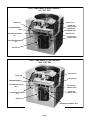
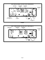
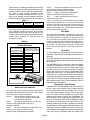
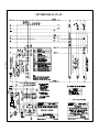
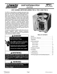
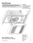
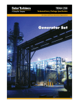
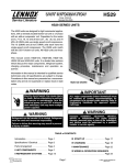
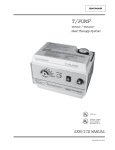
HS21
EARLY / LATE
MODEL SERIES
Corp. 9406−L3
Revised 10−2000
Service Literature
HS21 SERIES UNITS
HS21 early model units ( −411, −511, −651) and late model
units (−036, −048, −060) are high efficiency residential splitsystem condensing units which features a two-speed
compressor. Models are available in sizes ranging from 3
through 5 tons in either single or three-phase configuration.
The series features solid-state two-speed control, which regulates compressor speed in response to thermostat
demand. The HS21 is designed for use with an expansion
valve at the indoor coil.
This manual is divided into sections which discuss the components, refrigerant system, charging procedures,
maintenance and operation sequences.
Information contained in this manual is intended for use by
Lennox service technicians only. All specifications are
subject to change. Procedures outlined in this manual are
presented as a recommendation only and do not supersede or replace local or state codes. In the absence of
local or state codes, the guidelines and procedures outlined in this manual (except where noted) are
recommended only.
SPECIFICATIONS (Early Model)
Model No.
Condenser Coil
HS21-411
HS21-413
HS21-511
HS21-513
HS21-651
HS21-653
21.64/
20.81
21.64/
20.81
23.92/
23.01
3/8
2
3/8
2
3/8
2
20
24
20
24
20
24
3
1/6
3200
3
1/6
3200
4
1/4
4200
815
170
815
170
815
310
11lbs. 6oz.
3/8
7/8
11lbs. 14oz.
3/8
7/8
13lbs. 14oz.
3/8
1-1/8
Face area (sq.ft.)
outside / inside
Tube diameter (in.)
No. of Rows
Fins per inch
Diameter (in.)
No. of Blades
Condenser Fan
Motor hp
Cfm
Rpm
Watts
Refrigerant Charge (HCFC-22)
Liquid line connection (sweat)
Suction line connection (sweat)
LATE
MODEL
HS21 SHOWN
ELECTRICAL DATA (Early Model)
Model No.
Line voltage data - 60hz.
HS21-411
HS21-413
HS21-511
HS21-513
HS21-651
HS21-653
208/230/1ph
208/230/3ph
208/230/1ph
208/230/3ph
208/230/1ph
208/230/3ph
Compressor
Rated load amps
Power factor
Locked rotor amps
17.6
.98
90.0
12.7
.90
60.0
21.6
.98
120.0
15.8
.90
85.0
30.8
.92
141.0
19.9
.90
91.0
Outdoor Coil
Fan Motor
Full load amps
Locked rotor amps
1.0
1.9
1.0
1.9
1.0
1.9
1.0
1.9
1.7
2.9
1.7
2.9
40
23.0
25
16.9
45
28.0
35
20.8
60
40.2
45
26.6
Max fuse or circuit breaker size (amps)
*Minimum circuit ampacity
*Refer to National Electrical Code Manual to determine wire, fuse and disconnect size requirements.
NOTE − Extremes of operating range are plus 10% and minus 5% of line voltage
Page 1
© 1999 Lennox Industries Inc.
Litho U.S.A.
SPECIFICATIONS (Late Models)
Model No.
HS21-036
HS21-048
HS21-060
3
4
5
Nominal Tonnage
Liquid line in. (mm) o.d. connection (sweat)
3/8 (9.5)
Suction line in. (mm) o.d. connection (sweat)
7/8 (22.2)
1-1/8 (28.5)
Outer coil
21.77 (2.02)
24.06 (2.24)
Inner coil
21.11 (1.96)
23.33 (2.17)
Net
ft. (m
N t fface area sq. ft
( 2)
Condenser
Coil
Tube diameter in. (mm) & no. of rows
5/16 (7.9) 2
Fins per inch (m)
22 (866)
Diameter in. (mm) & no. of blades
Condenser
Fan
24 (610) 3
24 (610) 4
Motor hp
1/6 (124)
1/4 (187)
Cfm (L/s)
3200 (1510)
4200 (1980)
Rpm
815
Watts
170
*Refrigerant charge furnished (HCFC-22)
310
10 lbs. 10 oz. (4.80 kg)
11 lbs. 0 oz. (4.98 kg)
12 lbs. 4 oz. (5.55 kg)
328 (149)
329 (149)
352 (160)
Shipping weight lbs. (kg) 1 package
OPTIONAL ACCESSORIES - MUST BE ORDERED EXTRA
Mounting Base
MB2−L (69J07)
Low Ambient Kit
LB−57113BC (24H77)
Indoor Blower Speed Relay Kit
72G36
CCB1 EfficiencyPlus Humidity Control
35H00
EBR1 Blower Relay Kit
75H90
Compressor Monitor (Canada Only)
T6−1469 (45F08)
*Refrigerant charge is sufficient for 15 ft. (4.5 m) length line set.
ELECTRICAL DATA (Late Models)
Model No.
Line voltage data 60 hz
Rec. Max fuse/circuit breaker size (amps)
Condenser Coil
Fan Motor
HS21−048
208/230v − 1ph 208/230v − 3ph
HS21-060
208/230v − 1ph
208/230v − 3ph
208/230v − 1ph
208/230v − 3ph
40
25
45
35
60
45
23.0
16.9
28.0
20.8
40.2
26.6
Rated load amps
17.6
12.7
21.6
15.8
30.8
19.9
Power factor
.98
.90
.98
.90
.92
.90
Locked rotor amps
90.0
60.0
120.0
85.0
141.0
91.0
Full load amps
1.0
1.0
1.0
1.0
1.7
1.7
Locked rotor amps
1.9
1.9
1.9
1.9
2.9
2.9
*Minimum circuit ampacity
Compressor
HS21-036
*Refer to National or Canadian Electrical Code manual to determine wire, fuse and disconnect size requirements.
NOTE Extremes of operating range are plus 10% and minus 5% of line voltage.
Page 2
HS21 COMPONENTS (EARLY MODEL)
−411, −511, −651
LIQUID LINE
CONTROL BOX
LIQUID LINE
SERVICE VALVE
THERMOMETERWELL
COMPRESSOR
TERMINAL BOX
LOW PRESSURE SWITCH
S87
SUCTION LINE
SUCTION LINE
SERVICE VALVE
HIGH PRESSURE SWITCH
(S4)
MUFFLER
FIGURE 1
HS21 COMPONENTS (LATE MODEL)
−036, −048, −060
CONTROL BOX
LIQUID LINE
SUCTION LINE
THERMOMETERWELL
LOW PRESSURE SWITCH
(S87)
SUCTION LINE
SERVICE VALVE
LIQUID LINE
SERVICE VALVE
HIGH PRESSURE SWITCH
(S4)
MUFFLER
COMPRESSOR TERMINAL BOX
FIGURE 2
Page 3
HS21 SINGLE PHASE CONTROL BOX COMPONENTS
POTENTIAL
RELAY (K31)
COMPRESSOR
START CAPACITOR
(C7)
HIGH SPEED
CONTACTOR
(K69)
LOW SPEED
CONTACTOR
(K1)
DUAL
CAPACITOR
(C12)
TWO SPEED
CONTROL
(A14)
DISCONNECT
TAB
TRANSFORMER
(T19)
FIGURE 3
HS21 THREE PHASE CONTROL BOX COMPONENTS
OUTDOOR FAN
RELAY (K10)
LOW SPEED
CONTACTOR
(K1)
HIGH SPEED
CONTACTOR
(K69)
FAN CAPACITOR
(C1)
TWO SPEED
CONTROL
(A14)
DISCONNECT
TAB
TRANSFORMER
(T19)
FIGURE 4
Page 4
I−APPLICATION
1−Control Transformer T19
All major components (indoor blower/coils) must be
matched according to Lennox recommendations for the
compressor to be covered under warranty. Refer to Engineering Handbook for approved system matchups. A
misapplied system will cause erratic operation, can result in
early failure of compressor or other components, and could
affect the warranty.
ELECTROSTATIC DISCHARGE (ESD)
Precautions and Procedures
All units are equipped with a line voltage to 24VAC
transformer which supplies power to unit controls as
shown in table 1. The transformer is rated at 70VA and
has two primary voltage taps (red − 208V, orange − 230V,
and black − common). Refer to unit wiring diagram for
detailed information regarding unit wiring.
CAUTION
Electrostatic discharge can affect electronic
components. Take precautions during unit installation and service to protect the unit’s electronic
controls. Precautions will help to avoid control
exposure to electrostatic discharge by putting
the unit, the control and the technician at the
same electrostatic potential. Neutralize electrostatic charge by touching hand and all tools on an
unpainted unit surface before performing any
service procedure.
2−Contactors K1 and K69
The compressor is energized by a set of contactors (K1 and
K69) located in the control box. Contactors in HS21 units are
energized as shown in table 2.
Contactor K1 energizes low speed compressor operation in
all units (single-phase and three-phase.) In single-phase units
K1 is a double-pole double-break contactor and in threephase units K1 is a double-break contactor with three sets of
normally open contacts and two sets of normally closed contacts. K1 is also equipped with a set of single-pole
double-throw auxiliary contacts located on the side of the contactor. The contactor is energized in response to low speed
thermostat demand (from two-speed control jackplug
J44/P44 pin 9).
TABLE 2
Compressor Speed
II−UNIT COMPONENTS
HS21 unit components are shown in figures 1 and 2.
Low
High
A−Control Box Components
HS21 control box is shown in figures 3 and 4. The control
box is located in the top front section of the unit.
TABLE 1
HS21 Component
Two-Speed Control A14
Contactor K1
Contactor K69
High Pressure Limit S4
Low Pressure Limit S87
Fan Relay K10 (3 phase)
Potential Relay K31 (1 phase)
Crankcase Heater HR1
Compressor Fan Dual Capacitor
C12 (1 phase)
Compressor Start Capacitor C7
(1 phase)
Bleed Resistor R21 (1 phase)
Fan Capacitor C1 (3 phase)
Compressor B1
Outdoor Fan B4
Source of Power
24VAC from
Outdoor Unit
Transformer T19
Contactors Energized
Single-Phase
Three-Phase
K1
K1 & K69
K1
K69
In single-phase units, K1 also de-energizes the crankcase
heater and energizes the condenser fan during compressor
operation.
Contactor K69 energizes high speed operation in all units
(single-phase and three-phase). K69 is a double-break contactor with three sets of normally open contacts and two sets
of normally closed contacts for single-phase models, and is a
three pole double break contactor for three-phase models.
This contact arrangement provides unique switching characteristics for two-speed operation. K69 is also equipped with a
set of single-pole double-throw auxiliary contacts located on
the side of the contactor. The contactor is energized in response to high speed thermostat demand from JP44-8
(two-speed control jackplug J44/P44 pin 8).
DANGER
Line Voltage
Electric Shock Hazard.
May cause injury or death.
Line voltage is present at all components when unit is not in operation on
units with single pole contactors.
Disconnect all remote electrical power
supplies before opening this panel.
Unit may have multiple power supplies.
Page 5
Contactor Operation: Single-Phase Units
Low speed demand energizes contactor K1. K1 de-energizes the crankcase heater and energizes the
compressor and condenser fan. High speed demand
energizes both contactors K1 and K69. K69 N.O. contacts close to redirect the circuit to the high speed start
windings and the N.C. contacts open to de-energize the
low speed start windings. K69−2 N.C. contacts and
K69−2 N.O. contacts also switch when K69 is energized
to ensure that K1 is energized with K69 during high
speed operation (refer to unit wiring diagram).
Contactor Operation: Three-Phase Units
Low speed demand energizes contactor K1. K1 energizes the compressor and locks out contactor K69. High
speed demand de-energizes K1 and energizes contactor K69. K69 locks out K1, through the K69−1 contacts
and energizes the compressor on high speed.
K1 is wired so that when de-energized, the contactor forms a
parallel common connection to the motor windings for high
speed, forming a parallel Delta" connection for Copeland
compressors. When K1 is energized, the contactor forms a
series Delta connection to the compressor windings. Refer
to operation sequence in back of this manual for more information.
3−Outdoor Fan Relay K10 (three-phase only)
All three-phase HS21 series units use an outdoor fan
relay (K10) to control the operation of the condenser
fan and the crankcase heater. The relay energizes the
condenser fan and de-energizes the crankcase heater
during demand.
4−Potential Relay K31 (single-phase only)
All single-phase HS21 units use a potential relay to control the
operation of the compressor starting circuit. The relay is normally closed when the compressor (contactor K1) is
de-energized. Capacitor (C7) is connected in series to a set of
normally closed K31 contacts and assists the compressor in
starting. When K1 energizes, the compressor immediately
begins start-up. K31 remains de-energized during compressor start-up and the start capacitor (C7) remains in the circuit.
As the compressor gains speed K31 is energized by electromotive forces generated by the compressor. When K31
energizes, its contacts open to take the start capacitor out of
the circuit.
5−Fan Capacitor C1 (three-phase units only)
All three-phase HS21 series units use single-phase permanent split capacitor (PSC) fan motors which require an
external run capacitor. Ratings will be printed on side of capacitor.
6−Start Capacitor C7 (single-phase only)
All single-phase HS21 units are equipped with a start capacitor connected in parallel with the compressor side of
the dual capacitor. The capacitor is switched off by the potential relay when the compressor nears full speed. The
start capacitor is rated 145-175mfd. @ 330VAC in all singlephase units.
7−Bleed Resistor R21 (single-phase only)
All single-phase HS21 units are equipped with a bleed resistor
connected in parallel with start capacitor C7. The resistor is
used to slowly discharge the capacitor when not in use. R21 is
a 15,000 ohm 2 watt resistor.
8−Dual Capacitor C12 (single-phase only)
All single-phase HS21 units use a single dual capacitor to
maximize motor efficiency in both the fan motor and the
compressor, which use PSC motors. A dual capacitor has
two independent capacitors inside one can. Each side of the
capacitor has different ratings. Ratings will be printed on side
of capacitor. The dual capacitor is wired in parallel with the
start capacitor and is electrically connected as shown in the
unit wiring diagram.
9−Disconnect Tab
The disconnect tab has 10 pins where 10 wire connections
are made from the various components in the control box.
The disconnect tab simplifies the connections between the
components in the control box.
10−TSC5 Two Speed Control A14
The TSC (A14) two-speed control (figure 7) is a Lennox-built
control designed for use with two-speed condensing units.
The control provides automatic switching from low speed to
high speed operation and back. A14 is electrically connected
as shown in the unit wiring diagram. The two speed control is
covered in detail in section III.
Page 6
B−Unit Components
1−Compressor B1
5−Low Pressure Switch S87
All compressors are rated at 208/230 VAC and may be singlephase or three-phase. All compressors are equipped with
internal pressure relief valves set at 450+50 psig. Compressors in all units use insertion-type crankcase heaters. See
ELECTRICAL DATA" or compressor nameplate for specifications. Figure 5 shows the compressor terminal box.
C−Optional Equipment
1−Humidity control A20
TYPICAL TWO SPEED COMPRESSOR
TERMINAL BOX
COPELAND SINGLE PHASE SHOWN
T3
T8
T1
The CCB1 EfficiencyPlus Comfort Management System
may be used with the HS21 unit to control humidity. The EfficiencyPlus automatically controls the compressor and the
indoor blower, to maintain a selected level of relative humidity throughout the conditioned space during a thermostat
demand. The EfficiencyPlus DS" output is designed to directly control the variable speed motors used in the CB21,
G21V, CB31MV and G32V indoor units.
T7
T2
SINGLE
PHASE
S1 S2
2−EBR1 Control Kit A51
FIGURE 5
2−Compressor Heater HR1 (all units)
A crankcase heater is used on all HS21 models. The wellmounted, insertion-type heater is self-regulating.
Heaters are rated at 40 watts for all HS21 models. The
heater is thermostat-actuated and operates only when
demand is satified.
3−Outdoor Fan Motor B4
The table on page 1 of this manual shows the specifications
of outdoor fans used in all HS21 units. In single-phase units,
the outdoor fan is controlled by the compressor contactor K1.
In three-phase units, the outdoor fan is controlled by relay
K10. See figure 6 if outdoor fan motor replacement is necessary
FAN GUARD
EBR1 Blower Relay Kit provides the option of varying indoor
blower speeds of multi-tap motors when using the EfficiencyPlus with a two-speed HS21. When the EfficiencyPlus is
used with the HS21, most of the dehumidification is provided
by forcing the compressor into high speed when the thermostat calls for low speed. The kit provides more
dehumidification by simultaneously decreasing the indoor
blower speed.
3−Room Thermostat S1
The HS21 unit can be used with numerous types of thermostats. The two-heat two−cool electromechanical thermostat
(51H34) is recommended. The subbase is furnished with the
thermostat and features system selector switch (Off-HeatAuto-Cool) and fan switch (Auto-On) for continuous or
intermittent blower operation. The thermostat also has an indicator light to indicate low or high speed compressor
operation.
4−Low Pressure (Low Ambient) Switch S11
The HS21 unit will operate satisfactorily down to 45°F (7°C)
outdoor air temperature without any additional controls. For
cases where operation of the unit is required at low ambients, a Low Ambient Control Kit LB-57113BC (24H77) can
be added in the field, enabling the unit to operate properly
down to 30°F (-1°C).
1/4"
Condenser fan
and motor
All units are equipped with a SPST N.C. low pressure
switch mounted on the compressor suction line. The switch
opens, shutting off the compressor, when suction line pressure drops below 25+5 psig. When the pressure rises
above 55+5 psig the switch automatically resets (closes).
The switch is electrically connected in series with high pressure switch S4 in the two-speed control’s safety circuit.
Wiring
Drip loop
FIGURE 6
4−High Pressure Limit Switch S4
All units are equipped with a SPST N.C. high pressure
limit switch mounted on the compressor discharge line.
When the pressure rises above 410+10 psig, the switch
opens to shut off the compressor. The switch is manually
reset and is electrically connected in series with low pressure switch S87 in the two-speed control’s safety circuit.
Page 7
III−TSC5 TWO-SPEED CONTROL OPERATION
Normal Operation Sequence
The TSC (A14) two-speed control contains relays which
energize compressor operation in response to thermostat
demand. High speed operation can be energized and deenergized without passing through low speed. The control
also contains safety timed-off delays and compressor
over-temperature sensing which protect the compressor.
A timed-off delay in the control prevents short cycling by locking out compressor operation for five minutes after the end of
a thermostat demand or after a power failure. The control also
counts unit fault conditions." When the compressor stops due
to a safety limit trip, or if the compressor winding temperature
becomes too hot, the control’s internal cycle counter accumulates one fault. If three unit faults are counted during the same
thermostat demand, the control locks out" and stops all unit
operation. The control can be reset by breaking and remaking
thermostat demand. Unit faults are erased when power is interrupted. When thermostat demand changes stages,
compressor operation stops for approximately one minute to
allow refrigerant pressure to equalize in the system.
A manual override button aids servicing and troubleshooting,
on the control. The manual override button, when pressed
and released, bypasses the five-minute delay so low speed or
high speed operation can be immediately energized. However, the control provides a one-minute delay between speed
changes, which can not be bypassed.
Do not use the override button immediately after power-up. If
the button is pushed during the ten-second power-up delay, it
has no effect. The control completes the five-minute delay.
The control continually self-tests its internal circuits and uses
the diagnostic lights to indicate control failure.
1− The control begins a five-minute delay during which the
unit is not operational (control and outdoor unit do not respond to thermostat demand). Once the five-minute
delay is complete, the control waits in OFF mode for
thermostat demand.
2− After receiving a thermostat demand, the TSC delays
three seconds before responding.
3− Low speed demand (JP44-9) energizes low speed operation OR high speed demand (JP44-8) energizes high
speed operation.
4− During unit operation, if low speed demand changes to
high speed demand or if high speed demand changes to
low speed, the control delays three seconds before responding. Then, all unit operation stops for 60+5 seconds
(control de-energizes JP44-8 and JP44-9). This allows
refrigerant pressure to equalize in the system. At the end
of the 60+5 second delay, the control responds to whatever thermostat demand is present. If no thermostat
demand is present, the control resets (see unit fault conditions section) and returns to step 2 above.
5− When thermostat demand is satisfied, all unit operation
stops after a three-second delay (control de-energizes
JP44-8 and JP44-9), the control resets (see unit fault
conditions section) and returns to step two.
6− General Operation
On power-up, the control begins a ten-second initial
delay.
TSC5 (A14) TWO-SPEED CONTROL COMPONENTS
MODE
SELECTION
JUMPERS
OPTION 1 ENABLE
JUMPER
OPTION 2 ENABLE
JUMPER
DIAGNOSTIC LEDs
D8, D4, D2, D1
HEARTBEAT
LED
MANUAL
OVERRIDE
BUTTON
COMPRESSOR
SENSOR
CONNECTORS
Y1 LED
Y2 LED
OPTION 1
CONNECTOR
OPTION 2
CONNECTOR
SERVICE RELAY
CONNECTORS
MAIN CONTROL
PLUG
LOW SPEED HIGH SPEED
LED
LED
FIGURE 7
Page 8
TSC5 (A14) MAIN CONTROL PLUG
JP44-1
JP44-2
JP44-3
JP44-4
JP44-5
JP44-6
JP44-7
JP44-8
JP44-9
24VAC POWER (INPUT)
24VAC COMMON
24VAC (SPARE, NOT USED)
2nd STAGE THERMOSTAT DEMAND
THERMOSTAT COMMON (C)
1st STAGE THERMOSTAT DEMAND
24VAC FROM SAFETY SWITCHES
TO INTERNAL CONTACTOR COIL (INPUT)
HIGH SPEED (24VAC OUTPUT)
LOW SPEED (24VAC OUTPUT)
JP44
3
2
1
6
5
4
9
8
7
FIGURE 8
Two-Speed Control Fault Conditions
If the control is in low speed operation, high speed operation,
OFF" mode or speed change delay, the control counts" or
accumulates faults on an internal cycle counter. Only faults
which occur during compressor operation and which cause
the compressor to shut off are counted. After a fault is
counted, the control stops unit operation, resets and begins a
five-minute time delay (step 2, operation sequence). If the
control senses a fault at the end of five minutes, the unit will
not restart. If the control counts three faults during the same
thermostat demand, the control locks out unit operation.
IMPORTANT
If the control locks out, it can be reset by breaking
thermostat demand for about five seconds then remaking thermostat demand. Also, anytime thermostat demand is removed or power is interrupted, the
control resets to zero faults.
IMPORTANT
If the cycle counter counts three faults during the
same thermostat demand, the control locks out. The
outdoor unit remains inoperable until thermostat demand is broken. This indicates further troubleshooting is needed. Though the control can be reset by
breaking thermostat demand, the unit may remain inoperable. The high pressure or low pressure conditions may still exist and must be located and corrected before the unit can be placed back in service.
See diagnostic codes to determine problem.
IMPORTANT
Intermittent continuity (bad connection or failing
components) can cause false lockout or lit diagnostic lights. Check electrical connections thoroughly.
A fault occurs when:
1− Compressor operation is monitored by high and low
pressure switches. These controls are wired in series. If
either one trips, compressor operation is interrupted and
one fault is counted. The control locks out compressor
operation for a minimum of five minutes when a safety
device terminates operation. High pressure switch must
be reset manually but low pressure switch resets automatically.
It is likely that the control could count three unit faults
from the low pressure switch during a single thermostat demand since this switch resets automatically.
However, the cycle counter can only count unit faults
from the high pressure switch if the reset button is
pushed without interrupting thermostat demand.
2− On all units using the TSC two-speed control, terminals
S1 and S2 on the control are connected to temperature
sensors (thermistors) which monitor the temperature of
the compressor motor windings. The two-speed control
measures the resistance through the sensors. The sensors increase their resistance as temperature increases
(for example, too much superheat). When the resistance
through the sensors increases above a preset limit, the
control stops compressor operation for a minimum of
five minutes. As the compressor windings cool, the resistance through the sensors drops below the reset
limit, the control resets automatically and one fault is
counted.
Page 9
Check sensors by measuring resistance (ohms) through
the sensors with the wires disconnected from the control
(unit not running). The sensor wires are not polarity sensitive. Table 3 shows winding temperature sensor
resistance values which will cause the TSC to lock out.
When unit is operating normally, resistance through the
sensors should be below the trip value shown in table 3.
TABLE 3
Compressor Winding
Temperature Sensor
TSC5 Copeland Compressor
Trip Ohms
Temp. Rise
Reset Ohms
Temp. Fall
25K to 35K
8.4K to 10K
The control can be checked by comparing the resistance measured through the sensors to the voltage
measured across the sensor terminals with the unit
running. Table 4 shows voltage measured across twospeed control terminals S1 and S2 with the
compressor running.
TABLE 4
COMPRESSOR WINDING SENSOR
OPERATING RANGE
Resistance Through
Compressor Winding
Temperature Sensor
K-ohms (ohms x 1000)
0
1.0
5.5
6.9
8.4
10.0
16.0
20.0
24.0
25.0
30.0
35.0
Voltage Across TSC5
compressor sensor terminals
with Unit Running DC Volts
0
1.70 − 1.82
6.07 − 6.48
6.86 − 7.33
7.55 − 8.07
8.16 − 8.72
9.69 − 10.36
10.34 − 11.05
10.82 − 11.57
10.93 − 11.68
11.35 − 12.14
11.68 − 12.48
Latch 3:
After the unit operates in low speed for 30
minutes consecutively, it switches to high
speed until low speed demand is satisfied.
Recall:
Used in conjunction with the bypass
button to recall the stored problem codes.
Test:
Used in conjunction with the control
button to start test mode.
Latch 2 or 3 modes are recommended in high humidity
areas. If the jumper falls off or is removed, the control will
continue to operate in the previously set mode until the
control is reset due to loss of power, then the control will
default to the Normal mode. The latch feature does not affect the indoor blower operation.
TEST MODE
The control has a test mode. To initiate this mode, move
the jumper to the test position and push the control button.
The unit will operate in low speed for 10 seconds, turn off
for ten seconds, then operate in high speed for 10 seconds. The control will only go into the test mode if there is
no thermostat demand and 5 minutes has elapsed since
the unit ran. The indoor blower does not run during this
mode. The test mode cannot run more than once every 5
minutes.
LED LIGHTS
Y1 and Y2 lights are connected directly to the inputs from the
thermostat. They indicate low and high speed demand, respectively.
The HI and LO lights are connected directly across the contactor coils. They indicate if the high and low speed contactors
are energized.
The HEARTBEAT light is connected to the microcontroller
unit (MCU). It indicates when the control’s MCU is operating
correctly, and also when the control is in delay mode. It blinks
at a rate of four times a second when the MCU is operating
properly and at a rate of once every two seconds when in the
delay mode (such as the 1 or 5 minute delay). If the LED is
continuously on or off (assuming the power is on), the MCU is
not operating properly and the control needs to be replaced.
The D1, D2, D4, and D8 (see figure 7) diagnostic lights display diagnostic codes to aid in unit troubleshooting. Refer to
Diagnostic Code Table (table 5).
Reset
Range
Trip
Range
+
DC volts
Measured with unit running.
Diagnostic Code Display
MODE SELECTION JUMPERS
The control has six mode selection jumpers for selection of
operating modes and problem code recall or test. Choose
one of the first four modes for operation.
Normal:
Normal operation (default mode). Unit
runs on high or low speed as the indoor
thermostat load demands.
Latch 1:
After high speed demand is met, the unit
remains in high speed until the low speed
demand is satisfied.
Latch 2:
After the unit operates in low speed for 15
minutes consecutively, it switches to high
speed until low speed demand is satisfied.
A problem code is normally displayed only for the duration of
the error. There is one exception. During a lockout, the code
for the problem causing the lockout flashes once a second
even if the problem condition no longer exists. If other problems occur during a lockout condition, the codes for those
problems will be saved in memory, but not displayed. The
stored problem codes are displayed by recalling them from
memory. The diagnostic codes can be re-displayed by setting
the jumper to the recall position. The stored codes are displayed by pushing the push button. As previously mentioned,
the push button is used to bypass the five-minute delay and to
initiate the test mode. In addition, the button is used to step
back through the stored diagnostic codes and erase the diagnostic code memory. Diagnostic codes are recalled in the
Page 10
reverse order of actual occurrence. Each subsequent button
push will display additional codes until the last one, which will
stay on with additional button pushes. Hold the button down
until the lights go off (approximately five seconds) to erase the
memory. The control has a nonvolatile memory that stores the
63 most recent diagnostic codes. These codes are stored in
memory, even in the event of a power loss.
Not all codes cause lockouts or indicate problems. The purpose of the diagnostic lights is to let the installer or service
technician know what is going on with the entire system, not
just the two−speed control. Some codes do indicate malfunctions or problems with either the control or the HS21, while
others inform the technician of the unit’s status. All codes,
except for three, are stored in memory and may be recalled.
Code 1 − Power Loss for Two Electrical Cycles
This code indicates that the unit’s power skipped two
electrical cycles (33−40 milliseconds). It may suggest that
power to the unit is dirty" or is of low quality. Code 1 is
stored.
Code 2 − Input Indication
This code indicates that a change has been made and
that the control acknowledges the change. It does not indicate a problem condition. It indicates activity such as
jumper setting changes, delay overrides, or addition of an
optional safety device to Option 1 or 2. Code 2 is not
stored.
Code 3 − Unsteady Thermostat Input
Code 3 indicates intermittent inputs from the room thermostat. Most likely, there is a loose connection at the
thermostat when this condition appears. Code 3 is
stored.
Code 4 − Pressure Switch Opens < Two Minutes
If the low or high pressure switch opens after the compressor
has run for less than two minutes, Code 4 will be displayed.
This may indicate blockage or fan failure. Code 4 is stored. If
the unit still operates after code is displayed, the low pressure
switch stops operation (low pressure is auto−reset). Check for
low system charge.
Code 5 − Pressure Switch Opens > Two Minutes
If the low or high pressure switch opens after the compressor has run for more than two minutes, Code 5 is
displayed. This may indicate an improper charge or coil
obstruction. Code 5 is stored. If the unit still operates after
code is displayed, the low pressure switch stops operation (low pressure is auto−reset). Check for low system
charge.
TABLE 5
TSC5 DIAGNOSTICS CODES
CODE
NUMBER
DISPLAY LIGHTS
CONDITION
8
4
2
1
1
Power loss for two
cycles
OFF
OFF
OFF
ON
2
Input Indication
OFF
OFF
ON
OFF
3
Unsteady Input
OFF
OFF
ON
ON
4
Pressure Switch Open
<2 minutes
OFF
ON
OFF
OFF
5
Pressure Switch Open
> 2 minutes
OFF
ON
OFF
ON
6
Hot Compressor < 5
min. (or open sensor)
OFF
ON
ON
OFF
7
Hot Compressor > 5 min.
(or open sensor)
OFF
ON
ON
ON
8
Option 1 < 5 minutes
ON
OFF
OFF
OFF
9
Option 1 > 5 minutes
ON
OFF
OFF
ON
10
Option 2 Open
ON
OFF
ON
OFF
11
Compressor Sensor
Problem
ON
OFF
ON
ON
12
Not Used on TSC5
ON
ON
OFF
OFF
13
Not Used
ON
ON
OFF
ON
14
Test Mode
ON
ON
ON
OFF
15
No Jumper in place
Indication
ON
ON
ON
ON
Code 6 − Hot Compressor < Five Minutes
Code 6 indicates the compressor temperature exceeded
its limit after running less than five minutes. Code 6 is
stored.
Code 7 − Hot Compressor > Five Minutes
Code 7 indicates the compressor temperature exceeded
its limit after running more than five minutes. Code 7 is
stored.
Code 8 − Option 1 < Five Minutes
Code 8 occurs if the Option 1 safety device switch opens
after the compressor runs less than five minutes. Code 8 is
stored.
Code 9 − Option 1 > Five Minutes
Code 9 occurs if the Option 1 safety device switch opens after the compressor runs more than five minutes. Code 9 is
stored.
Code 10 − Option 2
Code 10 is displayed if the Option 2 safety device switch
opens. Code 10 is stored.
Page 11
Code 11 − Compressor Temperature Sensor Shorted
This code indicates that the compressor temperature sensor
wires have shorted together. Code 11 is stored.
CAUTION
Do not remove the jumpers unless additional
protection controls are going to be installed. If OPT
1 jumper is not connected to the NO pin, the control
will lock out the compressor. If OPT 2 is not connected to the NO pin, the display only shows the
problem code.
Code 12 − Not used on TSC5
This code does not pertain to the two−speed control (TSC5)
used on condensing units.
Code 13 − Not Used
This code may be used in future models of the two−speed
control, but at this time has no function and, therefore, is not
stored.
Code 14 − Test Mode
Code 14 does not indicate a problem. The control is in TEST
mode when this code is displayed. See Mode Jumper Selections section.
Code 15 − No Jumper in Place
Code 15 is displayed when the mode jumper is not in place.
Make sure jumper is placed securely across the selected set
of pins for the appropriate mode of operation.
SERVICE RELAY
The control has a built-in service relay. This relay controls
the thermostat service light or communicates with an alarm
device. The relay signals the alarm device in such a manner
that the alarm device can distinguish between a lockout and
a non-lockout condition. The relay contacts are normally
open when no problems or lockout conditions occur. A nonlockout condition is reported by closing the contacts for the
duration of the next no-demand period. If the control goes
into a lockout state, the relay will close and remain closed
until the next loss of demand. If the service light on the room
thermostat is connected to the service relay, the light will
turn on if the control is in a lockout. It will not turn on if the
control is detecting non-lockout problems. In order for the
service relay to indicate only a lockout condition, one side of
the relay must be wired to the alarm and the other side to
Y2. During a simultaneous Y1 and Y2 demand with a nonlockout condition, the alarm will energize for a very short
duration (.2 seconds). If both an alarm device and thermostat service lights are used, an additional external relay may
be required depending on the thermostat used.
OPTIONAL INPUTS
The control has two optional inputs for additional protection
devices. If options 1 or 2 are going to be used, move the three
pin mini-jumper to the YES side. OPT 1 input will lock out the
compressor on the third count. OPT 2 input will not lock out
the compressor at any time, but will display and store the
problem code (see Diagnostic code Table). These inputs are
designed for normally closed switches connected to 24VAC.
IV−REFRIGERANT SYSTEM
A−Plumbing
Field refrigerant piping consists of liquid and suction lines from
the indoor coil to the outdoor unit (sweat connections). Use
Lennox L10 series line sets as shown in table 6 or field fabricated refrigerant lines. Install filter drier, provided with unit, in
the liquid line as close as possible to the expansion device.
TABLE 6
HS21 UNIT
LIQUID
LINE
−410
−036
−510
−048
3/8 In
−650
−060
VAPOR
LINE
L10 LINE
SETS
L15 LINE
SETS
3/4 In
L10−41
20 ft − 50 ft.
L15−41
15 ft. − 50 ft.
7/8 In
L10−65
30 ft. − 50 ft.
L15−65
15 ft. − 50 ft.
1−1/8 In
FIELD FABRICATED
B−Discharge Muffler
All units are equipped with a discharge muffler located in the
discharge line of the compressor. The muffler attenuates discharge gas pulsations from the compressor to lower sound
levels. The discharge muffler is located immediately in front of
the compressor in the compressor compartment. See figure 1
or 2.
C−Thermometer Well
All units are equipped with a thermometer well for use in measuring liquid line temperature when charging the unit. The
thermometer well is used in all Lennox recommended charging procedures. It is located in the liquid line adjacent to the
liquid line service valve.
D−Service Valves
The liquid line and suction line service valves and gauge ports
are accessible by removing the compressor access cover.
Full service liquid and suction line valves are used. See figures 9 and 11. The service ports are used for leak testing,
evacuating, charging and checking charge.
Page 12
1−Liquid Line Service Valve
A full-service liquid line valve made by one of several
manufacturers may be used. All liquid line service valves
function the same way, differences are in construction. Valves
manufactured by Parker are forged assemblies. Valves
manufactured by Primore are brazed together. Valves are not
rebuildable. If a valve has failed it must be replaced. The liquid
line service valve for HS21−411, −511, and −060 is illustrated
in figure 9. The liquid line service valve for HS21−036, −048
and −060 is illustrated in figure 10.
The valve is equipped with a service port. There is no schrader valve installed in the liquid line service port. A service port
cap is supplied to seal off the port.
The liquid line service valve is a front and back seating valve.
When the valve is backseated the service port is not pressurized. The service port cap can be removed and gauge
connections can be made.
CAUTION
A schrader valve is not provided on the liquid line
service port. The service port cap is used to seal the
liquid line on the service valve. Access to service
port requires backseating the service valve to isolate
the service port from the system. Failure to do so will
cause refrigerant leakage.
LIQUID LINE SERVICE VALVE
HS21−411, −511, −651
TO
LINE
SET
TO CONDENSER
COIL
NO SCHRADER
IMPORTANT
SERVICE
PORT CAP
SERVICE PORT OPEN
TO LINE SET WHEN
FRONT SEATED AND
CLOSED (OFF) WHEN
BACK SEATED
A schrader valve is not
provided on the liquid
line service port. Valve
must be backseated to
turn off pressure to
service port.
KNIFE EDGE SEAL
VALVE STEM
USE SERVICE
WRENCH
(PART #18P66,
54B64 or 12P95)
STEM
CAP
FIGURE 9
To Access Service Port:
1− Remove the stem cap. Use a service wrench
to make sure the service valve is backseated.
2− Remove service port cap and connect high pressure
gauge to service port.
3− Using service wrench, open valve stem (one turn clockwise) from backseated position.
4− When finished using port, backseat stem with service
wrench. Tighten firmly.
5− Replace service port and stem cap. Tighten finger tight,
then tighten an additional 1/6 turn.
To Close Off Service Port:
1− Using service wrench, backseat valve.
a−Turn stem counterclockwise.
b−Tighten firmly.
To Open Liquid Line Service Valve:
1− Remove the stem cap with an adjustable wrench.
2− Using service wrench, backseat valve.
a−Turn stem counterclockwise until backseated.
b−Tighten firmly.
3− Replace stem cap, finger tighten then tighten an additional 1/6 turn.
To Close Liquid Line Service Valve:
1− Remove the stem cap with an adjustable wrench.
2− Turn the stem in clockwise with a service wrench to
front seat the valve. Tighten firmly.
3− Replace stem cap, finger tighten then tighten an additional 1/6 turn.
2−Suction Line (Seating Type) Service Valve
A full service non-backseating suction line service valve is
used on all HS21 series units. Different manufacturers of
valves may be used. All suction line service valves function
the same way, differences are in construction.
Valves manufactured by Parker are forged assemblies.
Primore and Aeroquip valves are brazed together. Valves
are not rebuildable. If a valve has failed it must be replaced. The suction line service valve for HS21−411, −511
and −060 is illustrated in figure 11. The suction line service
valve for HS21−036, −048 and −060 is illustrated in figure
12.
The valve is equipped with a service port. A schrader valve
is factory installed. A service port cap is supplied to protect
the schrader valve from contamination and assure a leak
free seal.
To Access Schrader Valve:
1− Remove service port cap with an adjustable wrench.
2− Connect gauge to the service port.
3− When testing is completed, replace service port cap.
Tighten finger tight, then an additional 1/6 turn.
To Open Suction Line Service Valve:
1− Remove stem cap with an adjustable wrench.
2− Using service wrench and 5/16" hex head extension
back the stem out counterclockwise until the valve stem
just touches the retaining ring.
3− Replace stem cap tighten firmly. Tighten finger tight,
then tighten an additional 1/6 turn.
Page 13
DANGER
LIQUID LINE SERVICE VALVE
HS21−036, −048, −060
(VALVE OPEN)
Do not attempt to backseat this valve. Attempts to
backseat this valve will cause snap ring to explode
from valve body under pressure of refrigerant.
Personal injury and unit damage will result.
STEM CAP
SERVICE
PORT
OUTLET TO
COMPRESSOR
SERVICE
PORT
CAP
To Close Suction Line Service Valve:
1− Remove stem cap with an adjustable wrench.
2− Use service wrench and 5/16" hex head extension turn
stem clockwise to seat the valve. Tighten firmly.
3− Replace stem cap. Tighten finger tight, then tighten an
additional 1/6 turn.
INLET (TO
INDOOR COIL)
V−CHARGING
SCHRADER VALVE
The unit is factory-charged with the amount of HCFC-22
refrigerant indicated on the unit rating plate. This
charge, as shown in the specification table on page 1, is
based on a matching indoor coil and outdoor coil with 15
feet of line set.
For varying lengths of line set, refer to table7 for refrigerant
charge adjustment. A blank space is provided on the unit rating plate to list actual field charge.
FIGURE 10
SUCTION LINE SERVICE VALVE
HS21−411, −511, −651
VALVE OPEN
INSERT HEX WRENCH
HERE (PART #49A71 AND
SERVICE WRENCH)
SNAP RING
KNIFE
EDGE
SEAL
INLET
(FROM INDOOR COIL)
OUTLET
(TO COMPRESSOR)
SERVICE PORT
FIGURE 11
SUCTION LINE (BALL TYPE) SERVICE VALVE
HS21−036, −048, −060
(VALVE OPEN)
SERVICE PORT
CAP
UNIT SIDE
Ounce per 5 foot (ml per mm) adjust
from 15 foot (4.5 m) line set*
1 ounce per 5 feet (30 ml per 1524 mm)
2 ounce per 5 feet (60 ml per 1524 mm)
3 ounce per 5 feet (90 ml per 1524 mm)
*If line set is greater than 15 ft. (4.5m) add this amount. If line set
is less than 15 feet (4.5m) subtract this amount
STEM CAP
SCHRADER VALVE
SERVICE
PORT
CAP
TABLE 7
LIQUID LINE
SET DIAMETER
1/4 in. (6 mm)
5/16 in. (8mm)
3/8 in. (10 mm)
Units are designed for line sets up to 50 ft. Consult Lennox Refrigerant Piping Manual (Corp. 9351-L9) for line
sets over 50 ft.
A−Leak Testing
After the line set has been connected to the indoor and
outdoor units, check the line set connections and indoor
unit for leaks.
WARNING
Refrigerant can be harmful if it is inhaled. Refrigerant must be used and recovered responsibly.
Failure to follow this warning may result in personal
injury or death.
SCHRADER
VALVE
SERVICE
PORT
WARNING
STEM
FIELD SIDE
BALL
(SHOWN OPEN)
Danger of explosion: Can cause
equipment damage, injury or death.
Never use oxygen to pressurize a refrigeration or air conditioning system.
Oxygen will explode on contact with
oil and could cause personal injury.
STEM CAP
FIGURE 12
Page 14
WARNING
IMPORTANT
Danger of explosion: Can cause equipment damage, injury or death. When using a high pressure gas
such as dry nitrogen to pressurize a refrigeration or
air conditioning system, use a regulator that can
control the pressure down to 1 or 2 psig (6.9 to 13.8
kPa).
Using an Electronic Leak Detector or Halide
1 − Connect a cylinder of HCFC-22 to the center port of
the manifold gauge set.
2 − With both manifold valves closed, open the valve on
the HCFC-22 cylinder (vapor only).
3 − Open the high pressure side of the manifold to allow
the HCFC-22 into the line set and indoor unit. Weigh in
a trace amount of HCFC-22. [A trace amount is a maximum of 2 ounces (57 g) or 3 pounds (31 kPa)
pressure.] Close the valve on the HCFC-22 cylinder
and the valve on the high pressure side of the manifold
gauge set. Disconnect the HCFC-22 cylinder.
4 − Connect a cylinder of nitrogen with a pressure regulating valve to the center port of the manifold gauge set.
5 − Connect the manifold gauge set high pressure hose to
the vapor valve service port. (Normally, the high pressure hose is connected to the liquid line port; however,
connecting it to the vapor port better protects the manifold gauge set from high pressure damage.)
6 − Adjust the nitrogen pressure to 150 psig (1034 kPa).
Open the valve on the high side of the manifold gauge
set which will pressurize line set and indoor unit.
7 − After a few minutes, open a refrigerant port to ensure
the refrigerant you added is adequate to be detected.
(Amounts of refrigerant will vary with line lengths.)
Check all joints for leaks. Purge nitrogen and
HCFC-22 mixture. Correct any leaks and recheck.
2 − Connect micron gauge.
Use a thermocouple or thermistor electronic vacuum
gauge that is calibrated in microns. Use an instrument
that reads from 50 microns to at least 10,000 microns.
1 − Connect manifold gauge set to the service valve ports:
low pressure gauge to vapor line service valve
high pressure gauge to liquid line service valve
2 − Connect micron gauge.
3 − Connect the vacuum pump (with vacuum gauge) to
the center port of the manifold gauge set.
4 − Open both manifold valves and start the vacuum
pump.
5 − Evacuate the line set and indoor unit to an absolute
pressure of 23,000 microns (29.01 inches of mercury). During the early stages of evacuation, it is
desirable to close the manifold gauge valve at least
once to determine if there is a rapid rise in absolute
pressure. A rapid rise in pressure indicates a relatively large leak. If this occurs, repeat the leak testing
procedure.
NOTE − The term absolute pressure means the total
actual pressure within a given volume or system,
above the absolute zero of pressure. Absolute pressure in a vacuum is equal to atmospheric pressure
minus vacuum pressure.
6 − When the absolute pressure reaches 23,000 microns
(29.01 inches of mercury), close the manifold gauge
valves, turn off the vacuum pump and disconnect the
manifold gauge center port hose from vacuum pump.
Attach the manifold center port hose to a nitrogen cylinder with pressure regulator set to 150 psig (1034
kPa) and purge the hose. Open the manifold gauge
valves to break the vacuum in the line set and indoor
unit. Close the manifold gauge valves.
3 − Connect the vacuum pump (with vacuum gauge) to
the center port of the manifold gauge set.
4 − Open both manifold valves and start the vacuum
pump.
B−Evacuating the System
Evacuating the system of noncondensables is critical for
proper operation of the unit. Noncondensables are defined as any gas that will not condense under
temperatures and pressures present during operation of
an air conditioning system. Noncondensables and water
vapor combine with refrigerant to produce substances that
corrode copper piping and compressor parts.
CAUTION
Danger of Equipment Damage.
Avoid deep vacuum operation. Do not use compressors to evacuate a system.
Extremely low vacuums can cause internal arcing
and compressor failure.
Damage caused by deep vacuum operation will void
warranty.
7 − Shut off the nitrogen cylinder and remove the manifold
gauge hose from the cylinder. Open the manifold
gauge valves to release the nitrogen from the line set
and indoor unit.
Page 15
8 − Reconnect the manifold gauge to the vacuum pump,
turn the pump on, and continue to evacuate the line
set and indoor unit until the absolute pressure does
not rise above 500 microns (29.9 inches of mercury)
within a 20−minute period after shutting off the vacuum
pump and closing the manifold gauge valves.
9 − When the absolute pressure requirement above has
been met, disconnect the manifold hose from the vacuum pump and connect it to an upright cylinder of
HCFC-22 refrigerant. Open the manifold gauge valves
to break the vacuum from 1 to 2 psig positive pressure
in the line set and indoor unit. Close manifold gauge
valves and shut off the HCFC-22 cylinder and remove
the manifold gauge set.
C−Charging
The following procedures are intended as a general guide for
use with expansion valve systems only. For best results, indoor temperature should be between 70 °F and 80 °F.
Outdoor temperature should be 60 °F or above. Slight variations in charging temperature and pressure should be
expected. Large variations may indicate a need for further
servicing.
The outdoor unit should be charged during warm weather.
However, applications arise in which charging must occur
in the colder months. The method of charging is determined by the unit’s refrigerant metering device and the
outdoor ambient temperature.
Measure the liquid line temperature and the outdoor ambient temperature as outlined below:
1 − Connect the manifold gauge set to the service valves:
low pressure gauge to vapor valve service port
high pressure gauge to liquid valve service port
Connect the center manifold hose to an upright cylinder of HCFC-22. Close manifold gauge set valves.
2 − Set the room thermostat to call for heat. This will
create the necessary load for properly charging the
system in the cooling cycle.
3 − Use a digital thermometer to record the outdoor ambient temperature.
4 − When the heating demand has been satisfied, switch
the thermostat to cooling mode with a set point of 68F
(20C). When pressures have stabilized, use a digital
thermometer to record the liquid line temperature.
5 − The outdoor temperature will determine which charging method to use. Proceed with the appropriate
charging procedure.
Weighing in the Charge Fixed Orifice or
TXV Systems – Outdoor Temp < 65F (18C)
If the system is void of refrigerant, or if the outdoor ambient
temperature is cool, the refrigerant charge should be
weighed into the unit. Do this after any leaks have been repaired.
1 − Recover the refrigerant from the unit.
2 − Conduct a leak check, then evacuate as previously
outlined.
3 − Weigh in the unit nameplate charge.
If weighing facilities are not available or if you are charging
the unit during warm weather, follow one of the other procedures outlined below.
Approach and Normal Operating Pressures
TXV Systems – Outdoor Temp. > 65F (18C)
The following procedure is intended as a general guide and
is for use on expansion valve systems only. For best results,
indoor temperature should be 70°F (21°C) to 80°F (26°C).
Monitor system pressures while charging.
1 − Record outdoor ambient temperature using a digital
thermometer.
2 − Attach high pressure gauge set and operate unit for
several minutes to allow system pressures to stabilize.
3 − Compare stabilized pressures with those provided in
tables 10 and 11, Normal Operating Pressures." Minor variations in these pressures may be expected
due to differences in installations. Significant differences could mean that the system is not properly
charged or that a problem exists with some component in the system. Pressures higher than those listed
indicate that the system is overcharged. Pressures
lower than those listed indicate that the system is undercharged. Verify adjusted charge using the
approach method.
4 − Outdoor temperature should be 65°F (18°C) or above.
Use the same digital thermometer used to check outdoor ambient temperature to check liquid line
temperature. Verify the unit charge using the approach method. The difference between the ambient
and liquid temperatures should match values given in
table 3. Refrigerant must be added to lower approach
temperature and removed to increase approach temperature. Loss of charge results in low capacity and
efficiency.
Page 16
5 − If the values don’t agree with the those in tables 8 and
9, add refrigerant to lower the approach temperature
or recover refrigerant from the system to increase the
approach temperature.
TABLE 8
VI−MAINTENANCE
WARNING
Electric shock hazard. Can cause injury or death. Before attempting to perform any service or maintenance, turn
the electrical power to unit OFF at disconnect switch(es). Unit may have
multiple power supplies.
APPROACH METHOD - EXPANSION VALVE SYSTEMS
Liquid Line °F Warmer Than Outside
Model
(Ambient) Temperature
4+1
4+1
3+1
HS21-411/413
HS21-511/513
HS21-651/653
TABLE 9
Maintenance and service must be performed by a qualified installer or service agency. At the beginning of each
cooling season, the system should be checked as follows:
APPROACH METHOD - EXPANSION VALVE SYSTEMS
Liquid Line °F Warmer Than Outside
Model
(Ambient) Temperature
7+1
7+1
8+1
HS21-036
HS21-048
HS21-060
4− When unit is properly charged liquid and suction line
pressures should approximate those in tables 10 or 11.
IMPORTANT
1 − Clean and inspect the outdoor coil. The coil may be
flushed with a water hose. Ensure the power is turned
off before you clean the coil.
2 − Condenser fan motor is prelubricated and sealed. No
further lubrication is needed.
3 − Visually inspect connecting lines and coils for evidence of oil leaks.
Use tables10 or 11 as a general guide for performing
maintenance checks. Tables 10 and 11 are not a procedure for charging the system. Minor variations in
these pressures may be expected due to differences
in installations. Significant deviations could mean
that the system is not properly charged or that a
problem exists with some component in the system.
Used prudently, tables 10 and 11could serve as a
useful service guide.
4 − Check wiring for loose connections.
5 − Check for correct voltage at unit (unit operating).
6 − Check amp−draw condenser fan motor.
Unit nameplate _________ Actual ____________ .
NOTE − If owner complains of insufficient cooling, the unit
should be gauged and refrigerant charge checked. Refer
to section on refrigerant charging in this instruction.
TABLE 10
NORMAL OPERATING PRESSURES - HIGH SPEED OPERATION
HS21-510
HS21-650
HS21-410
OUTDOOR COIL
LIQ. SUC. LIQ. SUC.
LIQ. SUC.
ENTERING AIR
+ 10
+ 10
+ 10
+ 10
+ 10 + 10
TEMPERATURE
PSIG PSIG PSIG PSIG PSIG PSIG
65° F (TXV)
69
138
73
160
72
149
72
165
76
185
74
173
75° F (TXV)
85° F (TXV)
74
192
78
220
76
202
95° F (TXV)
76
223
80
255
79
232
78
257
82
285
81
265
105° F (TXV)
TABLE 11
NORMAL OPERATING PRESSURES - HIGH SPEED OPERATION
HS21-048
HS21-060
HS21-036
OUTDOOR COIL
LIQ. SUC. LIQ. SUC.
LIQ. SUC.
ENTERING AIR
+ 10
+ 10
+ 10
+ 10
+ 10 + 10
TEMPERATURE
PSIG PSIG PSIG PSIG PSIG PSIG
65° F (TXV)
70
142
72
142
72
149
75
173
74
168
74
173
75° F (TXV)
85° F (TXV)
77
202
76
196
76
202
95° F (TXV)
78
238
77
227
78
218
80
267
79
260
79
265
105° F (TXV)
Indoor Coil
1 − Clean coil, if necessary.
2 − Check connecting lines and coils for evidence of oil
leaks.
3 − Check the condensate line and clean it if necessary.
Indoor Unit
1 − Clean or change filters.
2 − Adjust blower speed for cooling. Measure the pressure
drop over the coil to determine the correct blower CFM.
Refer to the unit information service manual for pressure
drop tables and procedure.
3 − Belt Drive Blowers − Check belt for wear and proper
tension.
4 − Check all wiring for loose connections
D−Oil Charge
5 − Check for correct voltage at unit (blower operating).
Factory oil charge in all HS21 series units is 70 fl. oz. Suniso
3GS.
6 − Check amp−draw on blower motor
Unit nameplate_________ Actual ____________.
Page 17
VII−Miscellaneous
If the fan orifice should ever need to be removed for service,
make sure the control box seals watertight before placing the
unit back in service. Figure 13 shows the components used
to make the control box watertight. Two screws securing the
top of the control box to the cabinet must have rubber washers installed. Also, the control box must be installed with a
foam-rubber weatherstrip installed along the top edge (between the control box and the cabinet).
HS21 CONTROL BOX WEATHERPROOFING
SCREWS WITH RUBBER WASHERS. WASHERS
PREVENT WATER FROM DRIPPING INTO CONTROL AREA. MAKE SURE WASHERS ARE IN GOOD
CONDITION AND MAKE SURE SCREWS SEAT SECURELY AND ARE NOT CROSS-THREADED.
WEATHERSTRIPPING BETWEEN CONTROL BOX
AND FAN ORIFICE PANEL.
USED TO PREVENT FAN
FROM THROWING WATER
INTO CONTROL BOX.
FIGURE 13
VIII−Operation Sequence - Compressor
Single-Phase Compressor Start-Up
Figure 14 shows single-phase compressor windings.
This compressor has a two speed capacitor-start, capacitor-run motor. For starting, the start and run capacitors
are in parallel to provide the proper starting torque. The
start capacitor is disconnected by the start relay when the
compressor comes up to speed. The run capacitor remains connected to the start winding and the motor runs
as a two-phase induction motor with improved power factor and torque characteristics provided by the capacitor.
Low speed compressor operation is provided by powering
the run windings (internally connected in series) from terminals 1 (common) and 7. The windings form a four-pole motor
operating at 1800 RPM. The four low speed start windings
are in series and are connected to terminals 1 (common) and
8. They are used with the start and run capacitors and start
relay to start and bring the motor up to speed.
High speed compressor operation is provided when the run
windings are connected in parallel; terminals 1 (common)
and 7 to L1 and terminal 2 to L2. The windings form a twopole motor operating at 3600 RPM. The two high speed start
windings are in series and are connected to terminals 1
(common) and 3.
Three-Phase Compressor Start-Up
Figure 15 shows the windings of three-phase two-speed
compressors. The compressors have two-speed, threephase induction motors. Capacitors are not needed to
provide the proper phase and torque characteristics.
Low speed operation is provided when the motor windings
are connected in a series Delta" circuit. The motor operates
at 1800 RPM.
High speed operation is provided when the motor windings
are connected in a parallel Delta" circuit. Normally closed
contacts on the low speed contactor provide this connection. The motor operates at 3600 RPM.
Page 18
SINGLE-PHASE MOTOR WINDINGS LOW SPEED
MOTOR LEAD TERMINALS
SINGLE-PHASE MOTOR WINDINGS HIGH SPEED
MOTOR LEAD TERMINALS
1
1
COMMON
COMMON
2
2
7
RUN WINDINGS
7
RUN WINDINGS
RUN
CAP.
START
CAP.
RUN
CAP.
START
CAP.
HIGH SPEED
START WINDINGS
3
HIGH SPEED
START WINDINGS
3
8
8
LOW SPEED
START WINDINGS
LOW SPEED
START WINDINGS
START RELAY
START RELAY
FIGURE 14
THREE-PHASE MOTOR WINDINGS LOW SPEED
SERIES DELTA" CIRCUIT
THREE-PHASE MOTOR WINDINGS HIGH SPEED
PARALLEL DELTA" CIRCUIT
T4
L1
L1
T1
T1
T6
L2
L3
COMPRESSOR
CONTACTOR K1-1
T3
T4
T2
L2
T3
T5
L3
FIGURE 15
Page 19
T6
T2
T5
IX − WIRING DIAGRAMS AND SEQUENCE OF OPERATION
HS21 SINGLE PHASE
−036, −048, 060
Page 20
HS21 SINGLE PHASE −411, −511, −651
4
17 21 24
20 5
22
16
18
4
11
Page 21
6
12
2
7 19
23
8
1
15
10
13
9
14
3
HS21 SINGLE PHASE UNITS
Electromechanical Thermostat Connected to HS21−411,511,651,036,048,060
SINGLE-PHASE STARTING SEQUENCE:
1− Line voltage feeds through L1 and L2 to energize outdoor transformer T19 and outdoor
unit. Crankcase heater is energized through relay K1 auxiliary contacts.
2− Transformer T19 provides 24VAC to TSC (A14) and contactors K1 and K69.
3− The indoor transformer supplies 24VAC to the indoor unit and the indoor thermostat.
4− On power-up, 24VAC is fed through JP44-1 and JP44-7 to the TSC. The TSC begins a 10 second power-up delay.
5− The TSC begins a 5 minute delay during which the outdoor unit is not operational.
After a 5 minute delay, the TSC waits in OFF" mode for 1st stage or 2nd stage
demand.
Page 22
SINGLE-PHASE COMPRESSOR START-UP:
Low Speed
6− 1st stage demand: If all safety circuits check out, TSC energizes JP44-9.
7− Contactor K1 is energized through K69-2 N.C. contacts. K1-2 contacts open to
de−energize the crankcase heater. All other K1 contacts close to start outdoor fan
operation and to begin compressor low speed start-up.
8− Compressor B1 terminal 1 and the outdoor fan circuit are energized by K1 contacts L1-T1. Compressor terminal 7 is energized by contactor K1 terminal L2-T2
through contactor K69 terminal T1-X1. Compressor terminal 8 (start winding) is
energized by contactor K1 terminal L2-T2 through the start (C7) and run (C5) capacitors and contactor K69 terminal T3-X3.
9− Outdoor fan B4 is energized when contactor K1 contacts L1-T1 and L2-T2 close.
10−As the compressor nears full speed, potential relay K31 energizes and K31 contacts open to de-energize the start capacitor.
High Speed
11−2nd stage demand: If all safety circuits check out, TSC energizes JP44-8.
12−Contactor K69 energizes and K69-2 auxiliary contacts close to energize contactor
K1. K1-2 auxiliary contacts open to de-energize the crankcase heater. All other K1
contacts close. K69 contacts L1-T1, L2-T2 and L3-T3 close while contacts T1-X1
and T3-X3 open.
13−Compressor B1 terminal 3 (start winding) is energized by contactor K1 terminal
L2-T2 through the start (C7) and the dual (C12) capacitors and through contactor
K69 terminal L3-T3. Compressor terminal 2 is energized by contactor K1 terminal
L2-T2, and contactor K69 terminal L2-T2. Compressor terminal 1 is energized directly by contactor K1 terminal L1-T1. Compressor terminal 7 is energized by contactor K1 terminal L1-T1 and through contactor K69 terminal L1-T1.
14−Outdoor fan B4 is energized when contactor K1 contacts L1-T1 and L2-T2 close.
15−As the compressor nears full speed, potential relay K31 energizes and K31 contacts open to de-energize start capacitor C7.
SINGLE-PHASE COOLING SEQUENCE:
16−1st stage cooling demand energizes TB15-Y1. TB15-Y1 energizes TSC terminal
JP44-6.
NOTE-2nd stage cooling demand may be energized directly without passing
through 1st stage.
17−TSC delays 3 seconds before responding to the new command.
18−If the unit is changing from 2nd stage to 1st stage demand, TSC initiates speed
change delay and de-energizes JP44-8 and JP44-9 to stop all unit operation for
60+5 seconds. After TSC completes the 60+5 second speed change delay or if
the unit is starting up in 1st stage directly from OFF mode, TSC checks safety circuits by looking for 24VAC at JP44-7 and by checking resistance through wires
connected to S1 and S2.
19−If all safety circuits check out, TSC energizes K1 and compressor begins low
speed start-up.
20−2nd stage cooling demand energizes TB15-Y1 and TB15-Y2. TB15-Y2 energizes
TSC terminal JP44-4. TB15-Y1 energizes TSC terminal JP44-6.
21−TSC delays 3 seconds before responding.
22−If the unit is changing from 1st stage to 2nd stage demand, the TSC initiates
speed change delay and de-energizes JP44-8 and JP44-9 to stop all unit operation for 60+5 seconds. After TSC completes the 60+5 second speed
change delay or if the unit is starting up in 2nd stage directly from OFF mode,
TSC checks safety circuits by looking for 24VAC at JP44-7 and by checking
resistance through wires connected to S1 and S2.
23−If all safety circuits check out, TSC energizes K1 and K69. Compressor begins
high speed start-up.
24−When thermostat demand is satisfied or if thermostat is switched OFF, all outdoor
unit operation stops after a delay of 3 seconds. TSC then starts a 5 minute timedoff delay.
HS21 THREE PHASE −036, −048, −060
Page 23
HS21 THREE PHASE −413, −513, −653
4
2
5
16 21 24
10
19
22 17 14
1
4
Page 24
3
7
18
11
14
23
13
1
8
6
15
12
20
9
HS21 THREE PHASE UNITS
Electromechanical Thermostat Connected to HS21−413,513,653,036,048,060
THREE-PHASE STARTING SEQUENCE:
1− Line voltage feeds through L1, L2, and L3 to energize outdoor transformer T19 and
outdoor unit. Crankcase heater is energized through relay K10-1 outdoor fan contacts.
2− Transformer T19 provides 24VAC to TSC (A14) and contactors K1 and K69.
3− The indoor transformer supplies 24VAC to the indoor unit, the indoor thermostat
and the outdoor fan relay K10.
4− On power-up, 24VAC is fed through JP44-1 and JP44-7 to the TSC. The TSC begins a 10 second power-up delay.
5− The TSC begins a 5 minute delay during which the outdoor unit is not operational.
After a 5 minute delay, the TSC waits in OFF" mode for 1st stage or 2nd stage
demand.
Page 25
THREE-PHASE COMPRESSOR START-UP:
Low Speed
6− Low speed demand energizes outdoor fan relay K10 and JP44−6. K10-1 switches
to energize the outdoor fan and de-energize the crankcase heater. Outdoor fan
begins operating immediately.
7− After appropriate time delay and if all safety circuits check out, TSC energizes
JP44-9. Contactor K1 is energized through K69-2 N.C. contacts.
8− K1 N.O. contacts close to begin compressor low speed start-up. K1 N.C. contacts
open to disconnect the high speed wiring circuitry.
9− Compressor B1 terminal 1 is energized by K1 contacts L1-T1. Compressor terminal 2 is energized by contactor K1 terminal L2-T2. Compressor terminal 3 is energized by contactor K1 terminal L3-T3. This arrangement forms a series DELTA
connection to the motor windings for low speed.
High Speed
10−High speed demand energizes JP44-4.
11−After appropriate time delay and if all safety circuits check out, TSC energizes
JP44-8. Contactor K69 is energized through K1-2 N.C. contacts.
12−When contactor K1 is de-energized, contacts K1-1 normally closed contacts form
a parallel DELTA connection to the motor windings for high speed.
13−N.O. K69-1 contacts close to begin compressor high speed start-up. Compressor
terminal 4 is energized by contactor K69 terminal L1-T1. Compressor terminal 6 is
energized by contactor K69 terminal L2-T2. Compressor terminal 5 is energized
by contactor K69 terminal L3-T3.
THREE-PHASE COOLING SEQUENCE:
14−1st stage cooling demand energizes TB15-Y1. TB15-Y1 energizes TSC terminal
JP44-6 and relay K10.
NOTE-2nd stage cooling demand may be energized directly without passing
through 1st stage.
15−Relay contacts K10-1 switch to energize the outdoor fan and to de-energize the
crankcase heater.
16−TSC delays 3 seconds before responding to the new command.
17−If the unit is changing from 2nd stage to 1st stage demand, TSC initiates speed
change delay and de-energizes JP44-8 and JP44-9 to stop all unit operation for
60+5 seconds. Outdoor fan continues to operate. After TSC completes the 60+5
second speed change delay or if the unit is starting up in 1st stage directly from
OFF mode, TSC checks safety circuits by looking for 24VAC at JP44-7 and by
checking resistance through wires connected to S1 and S2.
18−If all safety circuits check out, TSC energizes K1 and compressor begins low
speed start-up.
19−2nd stage cooling demand energizes TB15-Y1 and TB15-Y2. TB15-Y2 energizes
TSC terminal JP44-4. TB15-Y1 energizes TSC terminal JP44-6 and outdoor fan
relay K10.
20−Relay contacts K10-1 switch to energize the outdoor fan and to de-energize the
crankcase heater.
21−TSC delays 3 seconds before responding.
22−If the unit is changing from 1st stage to 2nd stage demand, the TSC initiates speed
change delay and de-energizes JP44-8 and JP44-9 to stop all unit operation for
60+5 seconds. After TSC completes the 60+5 second speed change delay or if
the unit is starting up in 2nd stage directly from OFF mode, TSC checks safety
circuits by looking for 24VAC at JP44-7 and by checking resistance through wires
connected to S1 and S2.
23−If all safety circuits check out, TSC energizes K69. Compressor begins high speed
start-up.
24−When thermostat demand is satisfied or if thermostat is switched OFF, all outdoor
unit operation stops after a delay of 3 seconds. TSC then starts a 5 minute timedoff delay.
FIELD WIRING DIAGRAM HS21 WITH CB21
SINGLE-PHASE
LINE VOLTAGE
FIELD WIRING
208-230/60/1
L2 L1
COMPRESSOR
CONTACTOR
REFER TO UNIT RATING
PLATE FOR MAXIMUM
CIRCUIT
AMPACITY
AND MAXIMUM FUSE
SIZE.
THREE-PHASE
LINE VOLTAGE
FIELD WIRING
208-230/60/3
L3L2L1
COMPRESSOR
CONTACTOR
USE COPPER
CONDUCTOR ONLY
FIELD WIRING DIAGRAM HS21 WITH CB31MV
K20 INDOOR
BLOWER RELAY
(Black)
(Orange)
CIRCUIT 1
4
1
6
3
5
7
9
REFER TO UNIT RATING PLATE FOR
MINIMUM CIRCUIT AMPACITY AND
MAXIMUM OVERCURRENT PROTECTION SIZE.
FIELD−SUPPLIED
WIRE NUTS
4
3
3
NOTE−USE COPPER
CONDUCTORS ONLY
FACTORY
INSTALLED
JUMPER
4
TO EXTERNAL LOAD 24VAC
AT .50AMP MAXIMUM
CB1
CIRCUIT
BREAKER
NEC/CEC CLASS 2 3VA
3
5
CCB1−1
TERMINAL
BLOCK
Page 26
FACTORY-SUPPLIED, FIELD-INSTALLED
JUMPERS REQUIRED
Humidity
Jumpers
Outdoor Unit
Control
Required
Y1 to Y2 and
Single-Speed
With CCB1
O to R
Condensing Unit
Humidity
Two-Speed
Control
O to R
Condensing Unit
DS to Y1 , Y1
Without
Single-Speed Conto Y2 and O to
CCB1
densing Unit
R and
Humidity
DS to Y1
Two-Speed
Control
O to R
Condensing Unit