1
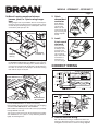
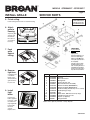
MODELS QTRE080FLT • QTRE110FLT
QTRE SERIES
FAN / LIGHT / NIGHT LIGHTS
Page 1
READ AND SAVE THESE INSTRUCTIONS
WARNING
CLEANING & MAINTENANCE
TO REDUCE THE RISK OF FIRE, ELECTRIC SHOCK, OR INJURY TO PERSONS, OBSERVE THE FOLLOWING:
1. Usethisunitonlyinthemannerintendedbythemanufacturer.
Ifyouhavequestions,contactthemanufacturerattheaddress
ortelephonenumberlistedinthewarranty.
2. Beforeservicingorcleaningunit,switchpoweroffatservice
panel and lock the service disconnecting means to prevent
powerfrombeingswitchedonaccidentally.Whentheservice
disconnecting means cannot be locked, securely fasten a
prominentwarningdevice,suchasatag,totheservicepanel.
3. Installation work and electrical wiring must be done by a
qualified person(s) in accordance with all applicable codes
and standards, including fire-rated construction codes and
standards.
4. Sufficientairisneededforpropercombustionandexhausting
of gases through the flue (chimney) of fuel burning equipment to prevent backdrafting. Follow the heating equipment
manufacturer’sguidelineandsafetystandardssuchasthose
publishedbytheNationalFireProtectionAssociation(NFPA),
andtheAmericanSocietyforHeating,RefrigerationandAir
ConditioningEngineers(ASHRAE),andthelocalcodeauthorities.
5. When cutting or drilling into wall or ceiling, do not damage
electricalwiringandotherhiddenutilities.
6. Ductedfansmustalwaysbeventedtotheoutdoors.
7. Acceptableforuseoveratuborshowerwhenconnectedto
aGFCI(GroundFaultCircuitInterrupter)-protectedbranch
circuit.
8. Thisunitmustbegrounded.
Forquietandefficientoperation,longlife,andattractiveappearance-lowerorremovegrilleandvacuuminteriorofunitwiththe
dustingbrushattachment.
CAUTION
1. Forgeneralventilatinguseonly.Donotusetoexhausthazardousorexplosivematerialsandvapors.
2. This product is designed for installation in ceilings up to a
12/12pitch(45degreeangle).Ductconnectormustpointup.
DONOTMOUNTTHISPRODUCTINAWALL.
3. Toavoidmotorbearingdamageandnoisyand/orunbalanced
impellers,keepdrywallspray,constructiondust,etc.offpower
unit.
4. Pleasereadspecificationlabelonproductforfurtherinformationandrequirements.
Installer: Leave this manual with
the homeowner.
Themotorispermanentlylubricatedandneverneedsoiling.Ifthe
motorbearingsaremakingexcessiveorunusualnoises,replace
theblowerassembly(includesmotorandimpeller).
OPERATION
Thefan,light,andnightlightcanbeoperatedseparately.Usea
3-functionwallcontrol.Donotuseadimmerswitchtooperate
thelight.See“ConnectWiring”fordetails.Useofspeedcontrols
otherthantheBroanModels78Vand78Wmaycauseamotor
hummingnoise.
WARRANTY
BROAN-NUTONETHREEYEARLIMITEDWARRANTY
Broan-NuTonewarrantstotheoriginalconsumerpurchaserofitsproducts
thatsuchproductswillbefreefromdefectsinmaterialsorworkmanship
foraperiodofthreeyearsfromthedateoforiginalpurchase.THEREARE
NOOTHERWARRANTIES,EXPRESSORIMPLIED,INCLUDING,BUT
NOTLIMITEDTO,IMPLIEDWARRANTIESOFMERCHANTABILITYOR
FITNESSFORAPARTICULARPURPOSE.
During this three-year period, Broan-NuTone will, at its option, repair or
replace,withoutcharge,anyproductorpartwhichisfoundtobedefective
undernormaluseandservice.
THIS WARRANTY DOES NOT EXTEND TO FLUORESCENT LAMP
STARTERS,TUBES,HALOGENANDINCANDESCENTBULBS,FUSES,
FILTERS,DUCTS,ROOFCAPS,WALLCAPSANDOTHERACCESSORIESFORDUCTING.Thiswarrantydoesnotcover(a)normalmaintenance
andserviceor(b)anyproductsorpartswhichhavebeensubjecttomisuse,negligence,accident,impropermaintenanceorrepair(otherthanby
Broan-NuTone),faultyinstallationorinstallationcontrarytorecommended
installationinstructions.
Thedurationofanimpliedwarrantyislimitedtothethree-yearperiodas
specifiedfortheexpresswarranty.Somestatesdonotallowlimitationonhow
longanimpliedwarrantylasts,sotheabovelimitationmaynotapplytoyou.
BROAN-NUTONE’SOBLIGATIONTOREPAIRORREPLACE,ATBROANNUTONE’S OPTION, SHALL BETHE PURCHASER’S SOLEAND EXCLUSIVEREMEDYUNDERTHISWARRANTY.BROAN-NUTONESHALL
NOT BE LIABLE FOR INCIDENTAL, CONSEQUENTIAL OR SPECIAL
DAMAGESARISING OUT OF OR IN CONNECTIONWITH PRODUCT
USE OR PERFORMANCE. Some states do not allow the exclusion or
limitationofincidentalorconsequentialdamages,sotheabovelimitation
maynotapplytoyou.
Thiswarrantygivesyouspecificlegalrights,andyoumayalsohaveother
rights, which vary from state to state.This warranty supersedes all prior
warranties.
To qualifyfor warranty service,you must (a) notify Broan-NuTone at the
addressortelephonenumberstatedbelow,(b)givethemodelnumberand
partidentificationand(c)describethenatureofanydefectintheproductor
part.Atthetimeofrequestingwarrantyservice,youmustpresentevidence
oftheoriginalpurchasedate.
Broan-NuToneLLC,926W.StateStreet,Hartford,Wisconsin53027
www.broan.com800-558-1711
Register your product online at: www.broan.com/register
MODELS QTRE080FLT • QTRE110FLT
Page 2
TYPICAL INSTALLATIONS
Housing mounted to I-joists.
Housing mounted anywhere between I-joists using hanger bars.
INSULATION
(Can be placed
around and over
fan housing.)
FAN
HOUSING
* Purchase
separately
4-IN.
ROUND
DUCT *
ROOF
CAP *
4-IN. ROUND
ELBOW(S) *
WALL
CAP *
Theunitwilloperatemostquietlyandefficientlywhenlocated
wheretheshortestpossibleductrunandminimumnumber
ofelbowswillbeneeded.
Use a roof cap or wall cap that has a built-in damper to
reducebackdrafts.
Housing mounted to joists.
Housing mounted anywhere between joists using hanger bars.
Plantosupplytheunitwithproperlinevoltageandappropriatepowercable.
INSTALL HOUSING & DUCT
1a. Mount
housing
to joist or
I-joist.
Housing mounted anywhere be- Housing mounted anywhere between trusses using hanger bars. tween trusses using hanger bars.
PLAN THE INSTALLATION
COOKING AREA
Do not install above or
inside this area.
45o
NOT FOR USE IN
A COOKING AREA.
45o
Cooking
Equipment
Floor
Useapliersto
bendhousing
TABSout
TABS
to900.Hold
housingin
placesothat
thehousing
tabscontact
thebottom
SPACER
ofthejoist.
(useformountingtoI-Joist)
Thehousing
mountswith
four(4)screws
ornails.Screw
ornailhousing
tojoistthrough
lowestholesin
eachmounting
flange,then
through
I-JOIST
highestholes.
NOTE:MountingtoI-JOIST(shown)requiresuseof
SPACERS(included)betweenthehighestholeof
eachmountingflangeandtheI-joist.
OR
MODELS QTRE080FLT • QTRE110FLT
Page 3
1b. Mount housing anywhere between
trusses, joists, or I-joists using hanger
bars.
Slidinghangerbarsareprovidedtoallowforaccuratepositioningofhousinganywherebetweenframing.Theycanbe
usedonalltypesofframing(I-joist,standardjoist,andtruss
construction)andspanupto24”.
2. Attach
damper/duct
connector.
Snapdamper/
ductconnector
ontohousing.
Makesureconnectorisflushwith
topofhousingand
damperflapfalls
closed.
TAB
SCREWS(4)
3. Install
4-inch round
ductwork.
ST
D
Connect4-inch
roundductwork
todamper/duct
connector.Run
ductworktoaroof
caporwallcap.
Tapeallductwork
connectionsto
makethemsecureandairtight.
MOUNTING
CHANNEL(2)
HANGER
BAR(4)
Attach the MOUNTING CHANNELS to the housing using
theSCREWSsupplied.MakesureTABSface“up”asshown.
Usethesetofchannelmountingholes(marked“STD”)to
mountthehousingflushwiththebottomofthedrywall.Use
the other set of holes (not marked) to mount the housing
flushwiththetopofthedrywall.
HOLEFOROPTIONAL
SCREWMOUNTING(4)
NAIL(4)
CONNECT WIRING
*SCREW(2)
BOTTOMEDGE
OFFRAMING
ExtendHANGERBARStothewidthoftheframing.
Hold ventilator in place with the hanger bar tabs wrapping
aroundtheBOTTOMEDGEOFTHEFRAMING.
NAILventilatortoframingorfastenwithscrews(notprovided)
throughHOLESnearnails.
Toensureanoise-freemount:Securehangerbarstogether
*with
SCREWS or use a pliers to crimp mounting channels
tightlyaroundhangerbars.
4. Connect electrical wiring.
Run120VAChousewiringtoinstallationlocation.Use
properULapprovedconnectortosecurehousewiringto
wiringplate.Connectwiresasshowninwiringdiagrams.
MODELS QTRE080FLT • QTRE110FLT
Page 4
INSTALL GRILLE
SERVICE PARTS
5. Finish ceiling.
Replacement parts
can be ordered on our
website. Please visit
us at www.broan.com
Installceilingmaterial.Cutoutaroundhousing.
6. Attach
grille to
housing.
Squeezegrille
springsand
insertthem
intotabson
eachsideof
housing.
SERVICE NOTE
To remove Blower
Assembly:
Unplug motor.
Remove thumbscrew (11)
from motor plate flange.
Find the single TAB on the
motor plate (located next to
the receptacle).
Push up near motor plate
tab while pushing out on
side of housing. Or insert a
straight-blade screwdriver
into slot in housing (next to
tab) and twist screwdriver.
7. Push
grille
against
ceiling.
8. Remove
light lens.
Carefullyinsert
asmallflatbladescrewdriverbetween
grilleandlens.
Prylensout.
9. Install
light
bulbs.
Fluorescent
bulbssupplied.
Purchasea4W
incandescent
nightlightbulb.
Insertbulbs
intotheir
sockets.
Replacelens.
Key No.
Part No.
1
2
3
4
5
6
7
8
9
10
11
12
13
97016466
97016449
98010102
99170245
97018011
97017855
97017856
97018273
99140199
99111401
99271381
99420665
97018014
QTHB1
Description
Housing
DuctConnector-4”
WiringPlate
Screw,#8-18X.375
WirePanel/HarnessAssembly
BlowerAssembly(QTRE080FLT)
BlowerAssembly(QTRE110FLT)
GrilleAssembly(includeskeynos.8,9&10)
GrilleSpring(2req’d)
Lens
Bulb,GU24,18WFluorescent(2req’d)
Thumbscrew,#8-18x.375
Spacer(2supplied)
HangerBarKit
Orderservicepartsby“PartNo.”-notby“KeyNo.”
99044456A