1
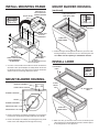
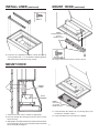
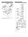
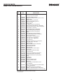
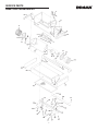
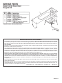
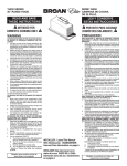
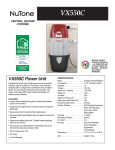
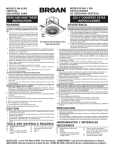
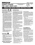
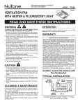
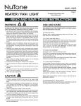
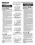
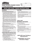
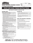
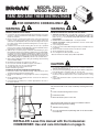
MODEL 103023 WOOD HOOD KIT READ AND SAVE THESE INSTRUCTIONS ! FOR DOMESTIC COOKING ONLY ! WARNING WARNING TO REDUCE THE RISK OF FIRE, ELECTRIC SHOCK, OR INJURY TO PERSONS, OBSERVE THE FOLLOWING: 1. Use this unit only in the manner intended by the manufacturer. If you have questions, contact the manufacturer at the address or telephone number listed in the warranty. 2. Before servicing or cleaning unit, switch power off at service panel and lock the service disconnecting means to prevent power from being switched on accidentally. When the service disconnecting means cannot be locked, securely fasten a prominent warning device, such as a tag, to the service panel. 3. Installation work and electrical wiring must be done by a qualified person(s) in accordance with all applicable codes and standards, including fire-rated construction codes and standards. 4. Sufficient air is needed for proper combustion and exhausting of gases through the flue (chimney) of fuel burning equipment to prevent backdrafting. Follow the heating equipment manufacturer’s guideline and safety standards such as those published by the National Fire Protection Association (NFPA), and the American Society of Heating, Refrigeration and Air Conditioning Engineers (ASHRAE), and the local code authorities. 5. When cutting or drilling into wall or ceiling, do not damage electrical wiring and other hidden utilities. 6. Ducted fans must always be vented to the outdoors. 7. Do not use this unit with an additional speed control device. 8. To reduce the risk of fire, use only metal ductwork. 9. Use with approved cord-connection kit only. 10.This unit must be grounded. TO REDUCE THE RISK OF A RANGE TOP GREASE FIRE: 1. Never leave surface units unattended at high settings. Boilovers cause smoking and greasy spillovers that may ignite. 2. Always turn hood ON when cooking at high heat or when cooking flaming foods. 3. Clean ventilating fans frequently. Grease should not be allowed to accumulate on fan or filter. 4. Use proper pan size. Always use cookware appropriate for the size of the surface element. TO REDUCE THE RISK OF INJURY TO PERSONS IN THE EVENT OF A RANGE TOP GREASE FIRE, OBSERVE THE FOLLOWING:* 1. SMOTHER FLAMES with a close-fitting lid, cookie sheet, or metal tray, then turn off the burner. BE CAREFUL TO PREVENT BURNS. If the flames do not go out immediately, EVACUATE AND CALL THE FIRE DEPARTMENT. 2. NEVER PICK UP A FLAMING PAN — You may be burned. 3. DO NOT USE WATER, including wet dishcloths or towels - violent steam explosion will result. 4. Use an extinguisher ONLY if: A. You know you have a Class ABC extinguisher and you already know how to operate it. B. The fire is small and contained in the area where it started. C. The fire department is being called. D. You can fight the fire with your back to an exit. * Based on “Kitchen Fire Safety Tips” published by NFPA. CAUTION 1. For general ventilating use only. Do not use to exhaust hazardous or explosive materials and vapors. 2. To avoid motor bearing damage and noisy and/or unbalanced impellers, keep drywall spray, construction dust, etc. off power unit. 3. For best capture of cooking impurities, your range hood should be mounted so that the bottom of the hood is 18-24” above the cooking surface. 4. Please read specification label on product for further information and requirements. This wood hood kit can be easily installed by following three basic steps: • Install a wood mounting frame in hood • Install the hood kit • Mount the hood in place on the wall This wood hood kit requires the previous installation of Broan Model 103123 Rough-in Kit including: 16” • 120 VAC electrical wiring • 3¼” x 10” metal ductwork (extending down to 16” above bottom of wood hood) 16” MIN. 19¼” MAX. INSTALLER: Leave this manual with the homeowner. HOMEOWNER: Use and care information on page 5. INSTALL MOUNTING FRAME SHEET METAL NUT MOUNT BLOWER HOUSING (continued) BRACKETS TO BE FLUSH WITH WOOD FRAMING PUSH HOUSING IN THIS DIRECTION #10 x 7/8 1/4-20 x 1/2 DUCT OPENING C L TO CENTER LINE OF SLOTS IN BRACKETS FRONT OF WOOD HOOD BACK OF WOOD HOOD 4. Fasten housing to mounting brackets with four (4) screws. Push housing toward top of wood hood, as far as mounting slots will allow. Make sure duct opening is toward back of hood. LENGTH OF FRONT & REAR BOARDS TO BE INSIDE WIDTH OF WOOD HOOD LENGTH OF (2) SIDE FRAMING PIECES (Mounting Brackets must fit inside frame) INSTALL LINER 1. Construct a wood frame which will fit the hood and allow the ductwork to line up with damper assembly. Attach the mounting brackets with the sheet metal nuts toward the hood front. Secure frame to hood using dimensions shown. CLEARANCE HOLE #8 x 3/8 MOUNT BLOWER HOUSING SHEET METAL NUT DAMPER ASSEMBLY SHEET METAL SCREW CLEARANCE HOLE BLOWER HOUSING WHEEL BLOWER ASSEMBLY MOUNTING ROD FRONT OF WOOD HOOD KNURLED NUT 2. Remove the blower assembly by unplugging it, loosening the knurled nuts and pivoting mounting rods away from blower. 3. Remove the damper assembly by unscrewing the two (2) sheet metal screws and sliding it back through the housing. 2 5. Make sure two (2) clearance holes in liner are lined up with sheet metal nuts on mounting brackets. Then screw liner pieces to mounting frame in nine (9) places. INSTALL LINER (continued) MOUNT HOOD (continued) #8 x ½ NOTE: Lamp Receptacles are toward REAR of hood. 6. Fasten the two, adjustable front liners to hood with eight (8) screws provided. Use a 7/ 64” dia. drill bit to drill through liners and fasten them securely where they overlap. 10. Plug in control unit and fasten to hood as shown. MOUNT HOOD POWER CORD DUCT OPENING NOTE: Filter Tabs are toward REAR of hood. 11. Install aluminum filter. Rotate two (2) retaining clips (on the hood liner) to hold filter in place. 7. Secure hood to wall, soffit or cabinets as appropriate. 12. Install an F20T12 fluorescent tube (not supplied). 8. Reach up through duct opening and connect power cord to blower housing. 9. Slide damper assembly up into ductwork and refasten to blower housing (using the two (2) screws removed in Step 3). Reinstall blower assembly and plug it in. 3 WOOD HOODS WIDER THAN 30” WIRING DIAGRAM DETERMINE FROM WIDTH OF HOOD SIDE LINER TOP LINER SIDE LINER 13. Add two (2) metal liners (not supplied) between top and side liners. Dimensions are shown above. 4 USE AND CARE SERVICE CAUTION ALWAYS DISCONNECT ELECTRIC POWER SUPPLY TO HOOD BEFORE SERVICING. OPERATION For best results, always turn on your hood before you begin cooking. Let hood run for a few minutes after you turn off range to allow hood to clear the air in the kitchen. Refer to page 4 for wiring diagram. Your hood uses an F20T12 fluorescent tube, available at most hardware stores or home centers. If tube flickers or does not light, check the prongs on ends of tube to make sure that they are properly seated in tube holders. Slide prongs into holders and rotate tube so that holders grip prongs and hold tube in place. If tube continues to flicker or does not light, replace tube. If ends of tube light but center does not, the starter may be defective. Your hood uses an FS-2 starter, located on underside of control unit. Remove old starter by pushing it in and turning it clockwise. Purchase a new starter at your local hardware store or home center, and install it by pushing it in and turning clockwise. If tube still does not light, order a 97007428 Ballast Transformer Kit from your Broan Distributor or from the Broan Service Department. Write Broan Mfg. Co., Inc., P. O. Box 140, Hartford, WI 53027. SPEED CONTROL The speed control allows unlimited selection of blower speeds and sound levels. The control turns the blower on to high speed and dials down to low speeds. HEAT SENTRY ™ Your hood is equipped with a Heat Sentry™ thermostat. This thermostat is a device that will turn or speed up the blower if it senses excess heat above the cooking surface. If blower is not on, or if it is running at low speed, the Heat Sentry™ will override the normal blower control and turn blower on to high speed. The blower will run until temperatures drop to normal levels. The blower will then return to its original setting. LIGHT TO REMOVE BLOWER FOR SERVICE The light switch is located just to the left of the speed control. CLEANING 1. Remove fluorescent tube. CAUTION ALWAYS DISCONNECT ELECTRIC POWER SUPPLY TO HOOD BEFORE CLEANING. 2. Rotate filter retaining clips out of way and remove filter. Clean hood with a mild detergent suitable for painted surfaces. DO NOT USE ABRASIVE CLOTH, STEEL WOOL PADS OR SCOURING POWDERS. To clean blower, remove filter and vacuum blower. Blower motor is lifetime lubricated and never needs oiling. Do not immerse blower in water. FILTER The aluminum filter in your hood should be cleaned frequently with detergent to avoid grease buildup. The filter is dishwasher safe. To remove filter, rotate retaining clips on either side of filter opening out of the way and pull filter out of hood. When replacing filter, make sure pull tabs on filter are toward the bottom and to the back of hood. BLOWER HOW TO AVOID A COMMON RANGE-TOP GREASE FIRE Your range hood provides a protective barrier between the cooking surface and the cabinets. Keep fan, filters and grease laden surfaces CLEAN according to instructions. Always turn hood ON when cooking at high heat to keep the cooking area and the hood cooler. Use high heat settings only when necessary. Never leave cooking surface unattended. Boil-over causes smoking and greasy spillovers that may ignite. Always use adequate-sized utensils. If preparing flaming foods, such as Cherries Jubilee, always turn hood ON to HIGH to prevent a high heat situation which can cause damage or fire. KNURLED NUT 3. Unplug blower and back off knurled nuts to ends of blower mounting rods. Do not remove nuts completely from rods. Support blower with one hand, slip rods out of brackets and swing them out of the way. Do not grasp blower by blower wheels. Wheels may be damaged. 4. Reinstall blower by slipping blower mounting rods into mounting brackets. Tighten knurled nuts securely, and plug blower in. Replace filter and fluorescent tubes. HOW TO EXTINGUISH A COMMON RANGE-TOP GREASE FIRE Never pick up a flaming pan. If dropped, flames can spread quickly. DO NOT USE WATER! A violent steam explosion may result. Wet dishcloths or towels are also dangerous. Smother flames with a close fitting lid, cookie sheet or metal tray. Flaming grease can also be extinguished with baking soda or a multi-purpose dry chemical extinguisher. Turn off surface units - if you can do so without getting burned. 5 SERVICE PARTS Model 103023 Wood Hood Kit KEY NO. PART NO. 97010327 1 2 3 4 5 6 7 8 9 10 11 12 13 14 15 16 17 18 19 20 21 22 25 26 27 28 29 30 31 32 33 34 35 36 37 38 39 40 41 42 43 44 45 97009818 97006078 98005221 99100379 97007406 97007487 93270619 99200202 97007488 99260473 99020138 99170245 98005212 99100491 97010736 99420464 99260476 97007314 99020139 97007486 98006455 97013583 99150470 98006454 97007725 99150491 97007726 97007428 99030132 99260481 99270670 97007424 97009817 99270550 98005860 99150490 99360118 99260491 99030310 99270553 99270650 99400054 99160319 46 99150591 47 48 ** 99160356 99150492 97007489 DESCRIPTION Complete Blower Assembly (Includes Key Nos. 12, 13, 14, 15, 16, 19 & 20) Control Box Wiring Harness Damper Assembly (Includes Key Nos. 3 & 4) Damper Flap Damper Bushing (2 Required) Blower Housing Wiring Harness Blower Housing Harness Clip ¼-20 Machine Screw (4 Required) Blower Box Mounting Bracket (2 Required) Sheet Metal Nut #10-24 U-Type (2 Required)* Blower Wheel - Clockwise #8-18 Tapping Screw (10 Required) Motor Retaining Ring (2 Required) Rubber Motor Mount (4 Required) Motor Blower Mounting Rod (2 Required) Blower Mounting Rod Nut (2 Required) Blower Scroll Housing Blower Wheel - Counterclockwise Liner Front Piece (2 Required) Liner Side Piece - Right Hand Liner Top Piece #8AB Sheet Metal Screw (13 Required) Liner Side Piece - Left Hand Aluminum Filter #8B Sheet Metal Screw (2 Required) Control Housing Cover Ballast Transformer Kit Speed Control Sheet Metal Nut, #10-16 U-Type* Ground Clip Heat Sentry™ Bracket Assembly Control Housing Fluorescent Lampholder (2 Required) Lampholder Retainer (2 Required) #10B Sheet Metal Screw (2 Required) Knob 3/8 Hex Nut Light Switch Fluorescent Starter FS-2* Fluorescent Starter Base Hole Plug #6-32 x 3/8 Pan Head Machine Screw (4 Required)* #10-12 x .625 Slotted Pan Head Sheet Metal Screw (8 Required)* #10-24 Machine Screw (2 Required)* #8AB x ½ Sheet Metal Screw (8 Required)* Parts Bag (Includes Key Nos. 8, 25, 46, 47 & 48) * Standard Hardware. May be purchased locally. **Not Illustrated 6 SERVICE PARTS Model 103023 Wood Hood Kit 11 10 2 8 3 12 12 13 4 17 13 48 28 7 BROAN-NUTONE ONE YEAR LIMITED WARRANTY Broan-NuTone warrants to the original consumer purchaser of its products that such products will be free from defects in materials or workmanship for a period of one year from the date of original purchase. THERE ARE NO OTHER WARRANTIES, EXPRESS OR IMPLIED, INCLUDING, BUT NOT LIMITED TO, IMPLIED WARRANTIES OF MERCHANTABILITY OR FITNESS FOR A PARTICULAR PURPOSE. During this one-year period, Broan-NuTone will, at its option, repair or replace, without charge, any product or part which is found to be defective under normal use and service. THIS WARRANTY DOES NOT EXTEND TO FLUORESCENT LAMP STARTERS AND TUBES. This warranty does not cover (a) normal maintenance and service or (b) any products or parts which have been subject to misuse, negligence, accident, improper maintenance or repair (other than by Broan-NuTone), faulty installation or installation contrary to recommended installation instructions. The duration of any implied warranty is limited to the one-year period as specified for the express warranty. Some states do not allow limitation on how long an implied warranty lasts, so the above limitation may not apply to you. BROAN-NUTONE’S OBLIGATION TO REPAIR OR REPLACE, AT BROAN-NUTONE’S OPTION, SHALL BE THE PURCHASER’S SOLE AND EXCLUSIVE REMEDY UNDER THIS WARRANTY. BROAN-NUTONE SHALL NOT BE LIABLE FOR INCIDENTAL, CONSEQUENTIAL OR SPECIAL DAMAGES ARISING OUT OF OR IN CONNECTION WITH PRODUCT USE OR PERFORMANCE. Some states do not allow the exclusion or limitation of incidental or consequential damages, so the above limitation or exclusion may not apply to you. This warranty gives you specific legal rights, and you may also have other rights, which vary from state to state. This warranty supersedes all prior warranties. To qualify for warranty service, you must (a) notify Broan-NuTone at the address or telephone number below, (b) give the model number and part identification and (c) describe the nature of any defect in the product or part. At the time of requesting warranty service, you must present evidence of the original purchase date. Broan-NuTone LLC Hartford, Wisconsin www.broan.com 800-558-1711 99040917Y