1
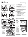
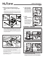
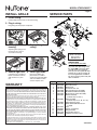
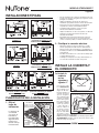
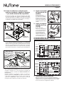
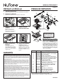
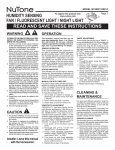
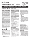
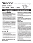
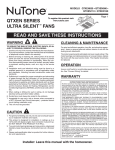
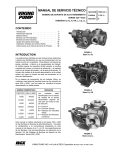
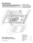
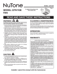
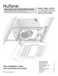
MODEL QTXEN110SFLT
Page 1
HUMIDITY SENSING
FAN / FLUORESCENT LIGHT / NIGHT LIGHT
READ AND SAVE THESE INSTRUCTIONS
To register this product visit:
www.nutone.com
WARNING
OPERATION
TO REDUCE THE RISK OF FIRE, ELECTRIC SHOCK, OR INJURY TO PERSONS,
OBSERVE THE FOLLOWING:
The humidity control and fan can be operated separately. Do not use a dimmer
switch to operate the humidity control or
light. See “Connect Wiring” for details.
1. Use this unit only in the manner intended
by the manufacturer. If you have questions,
contact the manufacturer at the address or
telephone number listed in the warranty.
2. Before servicing or cleaning unit, switch
power off at service panel and lock the service disconnecting means to prevent power
from being switched on accidentally. When
the service disconnecting means cannot be
locked, securely fasten a prominent warning
device, such as a tag, to the service panel.
3. Installation work and electrical wiring must be
done by a qualified person(s) in accordance
with all applicable codes and standards,
including fire-rated construction codes and
standards.
4. Sufficient air is needed for proper combustion and exhausting of gases through the
flue (chimney) of fuel burning equipment to
prevent backdrafting.Follow the heating equipment manufacturer’s guideline and safety
standards such as those published by the
National Fire Protection Association (NFPA),
and the American Society for Heating, Refrigeration and Air Conditioning Engineers
(ASHRAE), and the local code authorities.
5. When cutting or drilling into wall or ceiling, do
not damage electrical wiring and other hidden
utilities.
6. Ducted fans must always be vented to the
outdoors.
7. Acceptable for use over a tub or shower when
connected to a GFCI (Ground Fault Circuit
Interrupter) - protected branch circuit.
8. This unit must be grounded.
CAUTION
1. For general ventilating use only. Do not use
to exhaust hazardous or explosive materials
and vapors.
2. This product is designed for installation in flat
ceilings only. DO NOT MOUNT THIS PRODUCT IN A WALL.
3. To avoid motor bearing damage and noisy
and/or unbalanced impellers, keep drywall
spray, construction dust, etc. off power unit.
4. Please read specification label on product for
further information and requirements.
Installer: Leave this manual
with the homeowner.
SENSOR OPERATION
This humidity-sensing fan responds to: (a)
rapid to moderate humidity increases and
(b) humidity above a 50%-80% relative
humidity (RH) set-point. (a) and (b) are
set with “HUMIDITY” adjustment. Fan may
occasionally turn on when environmental
conditions change. If the fan continuously
responds to changing environmental conditions, “HUMIDITY” adjustment may be
required (see section below).
STATUS INDICATOR
This indicator can only be seen by looking
directly at it. Normal mode is 5-seconds on
and off. If it blinks rapidly for 5-seconds and
then off, check sensor connections on grille
and fan housing.
MANUAL ON WITH TIMED OFF
For odor or vapor control, the fan can be
energized by cycling its wall-mounted switch
if one is installed. Once the fan has been
turned on in this manner, it will remain on
for the set “MINUTES” period.
To manually energize the fan:
1. Go to Step 2 if switch is already on;
otherwise, turn switch on for more than
1 second.
2. Switch off for less than 1 second.
3. Switch back on and fan will turn on.
HUMIDITY ADJUSTMENT
“HUMIDITY” has been factory set for most
shower applications. If the fan is in a tub
area or is used for dampness control, the
“HUMIDITY” may need to be decreased
toward 50% RH. If the control is responding
too often to changing environmental conditions, adjustment toward 80% RH may be
required. To adjust the “HUMIDITY”:
1. Turn power off at electrical service
panel.
2. Through the grille, locate the “HUMIDITY”
screwdriver slot.
3. Using a small, flat-blade screwdriver,
carefully rotate “HUMIDITY” adjustment
toward 50 or 80.
4. Turn power on and check operation by
turning on shower or other humidity
source until fan turns on.
5. Repeat above steps if necessary.
TIMER ADJUSTMENT
This humidity-sensing fan has a timer. It is
user-adjustable from 5 to 60 minutes and is
factory-set at 20 minutes. The timer controls
how long the fan remains on after (a) rise
in humidity and (b) humidity level are both
below the user-adjustable “HUMIDITY”
setting or after being energized by cycling
power switch.
To adjust the timer:
1. Disconnect power at electrical service
panel.
2. Through the grille, locate the “MINUTES”
screwdriver slot.
3. Using a small, flat-blade screwdriver,
carefully rotate “MINUTES” adjustment
to desired setting (5 to 60 minutes).
4. Check operation by cycling power switch
as instructed under “MANUAL ON WITH
TIMED OFF” or by turning on a humidity
source until fan turns on.
5. Check timer setting with watch or clock
after turning humidity source off if it was
turned on in Step 4.
6. Repeat above steps if necessary.
CLEANING &
MAINTENANCE
For quiet and efficient operation, long life,
and attractive appearance - lower or remove
grille and vacuum interior of unit with a dusting brush attachment.
The motor is permanently lubricated and
never needs oiling. If the motor bearings
are making excessive or unusual noises,
replace the motor/blower wheel assembly.
SENSOR CLEANING
The humidity sensor is mounted in the grille.
The sensor will operate most reliably when
cleaned occasionally as follows:
1. Disconnect power at service entrance.
2. Remove the grille. Use a dry dustcloth,
clean toothbrush, or lightly vacuum to
clean sensor and grille. DO NOT USE
ABRASIVE CLOTH, STEEL WOOL
PADS, OR SCOURING POWDERS.
3. DO NOT USE cleaning sprays, solvents,
or water on or near the sensor!
MODEL QTXEN110SFLT
Page 2
TYPICAL INSTALLATIONS
Housing mounted to
I-joists.
Housing mounted anywhere
between I-joists using
hanger bars.
• Locateunitabove(GFCIprotectedcircuitrequired)or
within 5 feet of shower head.
• Locateunitawayfromheatingorcoolingsources
which can affect humidity levels.
• Donotlocatenearwindow.Unitmayrespondtothe
outdoor humidity level.
• Unitmustbeinstalledinceilingtoproperlysense
moisture.
• Locateunitonlyonflatceilingsupto12feethighfor
proper sensing.
• Thefanwilloperatemostefficientlywhenlocated
where the shortest possible duct run and minimum
number of elbows will be needed.
2. Plan the wiring.
• Plantosupplytheunitwithproperlinevoltageand appropriate power cable. Power cable should be
routed to the switch box first and then to the unit
(See “CONNECT WIRING” on page 3).
• Donotoperatethisunitwithaspeedcontrol. Damage to the sensor unit will result.
• Lightornight-lightmaybeinstalledwithawall- mounted motion control.
Housing mounted to joists.
Housing mounted
anywhere between
joists using hanger bars.
INSTALL HOUSING &
DUCT
1a. Mount
housing
to joist or
I-joist.
Housing mounted anywhere
between trusses using
hanger bars.
Housing mounted anywhere
between trusses using hanger
bars.
PLAN THE INSTALLATION
1. Choose the
installation
location.
The location of
your humidity
sensing
fan is very
important. Use
the following
guidelines for
best operation:
INSULATION
(Can be placed
around and over fan
housing.)
FAN
HOUSING 6-IN.
ROUND DUCT*
Purchase
* separately 6-IN. ROUND
ELBOW(S)*
ROOF
CAP*
WALL
CAP*
Use a pliers to
bend housing
TABS
TABS out
to 900. Hold
housing in
place so that
the housing
SPACER
tabs contact
(use for mounting to I-Joist)
the bottom
of the joist.
The housing
mounts with
four (4) screws
or nails. Screw
or nail housing
to joist through
lowest holes in
each mounting
I-JOIST
flange, then
through highest holes. NOTE: Mounting to I-JOIST
(shown) requires use of SPACERS (included)
between the highest hole of each mounting flange
and the I-joist.
OR
MODEL QTXEN110SFLT
Page 3
1b. Mount housing anywhere between
trusses, joists, or I-joists using hanger
bars.
Sliding hanger bars are provided to allow for accurate positioning of housing anywhere between framing. They can be
used on all types of framing (I-joist, standard joist, and truss
construction) and span up to 24”.
2. Attach damper/
duct connector.
Snap damper / duct connector onto housing. Make
sure connector is flush
with top of housing and
damper flap falls closed.
TAB
SCREWS (4)
3. Install
6-inch round ductwork.
MOUNTING
CHANNEL (2)
HANGER
BAR (4)
Connect 6-inch round
ductwork to damper / duct
connector. Run ductwork
to a roof cap or wall cap.
Tape all ductwork connections to make them
secure and air tight.
CONNECT WIRING
Attach the MOUNTING CHANNELS to the housing using the
SCREWS supplied. Make sure TABS are oriented as shown.
Use the set of mounting holes (marked “STD”) to mount the
housing flush with the bottom of the drywall. Use the other
set of holes (not marked) to mount the housing flush with
the top of the drywall.
WIRING OPTION #1
MODEL 66V, 66W
3-FUNCTION CONTROL (PURCHASE SEPARATELY)
LIGHT
(ON/OFF)
BLK
BLU
RED
RED
LIGHT
COM
NIGHT LIGHT
(ON/OFF)
HOLE FOR OPTIONAL
SCREW MOUNTING (4)
* SCREW (2)
BLK
FAN
(AUTO/OFF)
ORG
BLK
HUMIDITY
CONTROL
BRN
BLK
120
VAC
LINE
IN
NIGHT LIGHT
WHT
WHT
WHT
GRD
GRD
FAN
WHT
WHT
WHT
SWITCH BOX
UNIT
WIRING OPTION #2 - Fan can be turned ON, OFF, or set to operate automatically.
MODEL 77DV, 77DW
4-FUNCTION CONTROL (PURCHASE SEPARATELY)
BLK
NAIL (4)
BOTTOM EDGE
OF FRAMING
Extend HANGER BARS to the width of the framing.
Hold ventilator in place with the hanger bar tabs wrapping
around the BOTTOM EDGE OF THE FRAMING.
NAIL ventilator to framing or fasten with screws (not provided)
through HOLES near nails.
*
To ensure a noise-free mount: Secure hanger bars together
with SCREWS or use a pliers to crimp mounting channels
tightly around hanger bars.
FAN
(ON/OFF/AUTO)
BLK
RED
RED
ORG
BLU
BLK
BRN
COM
NIGHT LIGHT
(ON/OFF)
LIGHT
(ON/OFF)
BLK
120
VAC WHT
LINE
IN
GRD
HUMIDITY
CONTROL
FAN
WHT
WHT
WHT
WHT
RED
RED
BLK
BLU
NIGHT LIGHT
COM
BLK
WHT
LIGHT
WHT
GRD
SWITCH BOX
1. Connect electrical wiring.
UNIT
Run 120 VAC house wiring to installation location. Use
proper UL approved connector to secure house wiring to
wiring plate. Connect wires as shown in wiring diagrams.
MODEL QTXEN110SFLT
INSTALL GRILLE
Page 4
SERVICE PARTS
1. Finish ceiling.
Install ceiling material. Cut out around housing.
2. Plug in wiring.
12
2
13
1
Plug wiring into the proper receptacles.
12
6
3
7
13
3. Attach grille to
housing.
4. Push grille against
ceiling.
Squeeze grille springs and
insert them into slots on
each side of housing.
TAB
5
15
9
14
10
8
5. Remove light lens. 6. Install light bulbs.
Fluorescent bulbs supplied. Purchase a 4W incandescent night-light bulb
and screw bulbs into their
sockets. Replace lens.
WARRANTY
NUTONE THREE YEAR LIMITED WARRANTY
NuTone warrants to the original consumer purchaser of its products that such products will
be free from defects in materials or workmanship for a period of three years from the date of
original purchase. THERE ARE NO OTHER WARRANTIES, EXPRESS OR IMPLIED, INCLUDING,
BUT NOT LIMITED TO, IMPLIED WARRANTIES OF MERCHANTABILITY OR FITNESS FOR A
PARTICULAR PURPOSE.
During this three-year period, NuTone will, at its option, repair or replace, without charge, any
product or part which is found to be defective under normal use and service.
THIS WARRANTY DOES NOT EXTEND TO FLUORESCENT LAMP STARTERS AND TUBES. This
warranty does not cover (a) normal maintenance and service or (b) any products or parts which
have been subject to misuse, negligence, accident, improper maintenance or repair (other than
by NuTone), faulty installation or installation contrary to recommended installation instructions.
The duration of an implied warranty is limited to the three-year period as specified for the
express warranty. Some states do not allow limitation on how long an implied warranty lasts,
so the above limitation may not apply to you.
NuTone’S OBLIGATION TO REPAIR OR REPLACE, AT NUTONE’S OPTION, SHALL BE THE
PURCHASER’S SOLE AND EXCLUSIVE REMEDY UNDER THIS WARRANTY. NUTONE SHALL
NOT BE LIABLE FOR INCIDENTAL, CONSEQUENTIAL OR SPECIAL DAMAGES ARISING OUT
OF OR IN CONNECTION WITH PRODUCT USE OR PERFORMANCE. Some states do not allow
the exclusion or limitation of incidental or consequential damages, so the above limitation
may not apply to you.
This warranty gives you specific legal rights, and you may also have other rights, which vary
from state to state. This warranty supersedes all prior warranties.
To qualify for warranty service, you must (a) notify NuTone at the address or telephone number
stated below, (b) give the model number and part identification and (c) describe the nature of
any defect in the product or part. At the time of requesting warranty service, you must present
evidence of the original purchase date.
Broan-NuTone LLC Hartford, Wisconsin www.nutone.com 888-336-3948
Replacement parts can be
ordered on our website.
Please visit us at
www.nutone.com
SERVICE NOTE
To remove Blower Assembly:
Unplug motor. Remove thumbscrew
(15) from motor plate flange. Find
the single TAB on the motor plate
(located next to the receptacle).
Push up near motor plate tab while
pushing out on side of housing. Or
insert a straight-blade screwdriver
into slot in housing (next to tab) and
twist screwdriver.
11
Carefully insert a small flatblade screwdriver between
grille and lens. Pry lens
out.
4
Key No.
Part No.
1
2
3
4
5
6
7
97016466
97016450
98010102
99170245
97017086
97017999
97017083
97017087
8
97016967
9
10
99140199
99271381
11
12
13
14
15
99111345
97018014
QTNHB1
99271344
99420665
Description
Housing
Duct Connector-6”
Wiring Plate
Screw, #8-18 X .375
Wire Panel/Harness Assembly
Motor/Blower Wheel Assembly
Motor Plate & Control Assembly
Blower Assembly
(includes key nos. 6 & 7)
Grille Assembly
(includes key nos. 9, 10, 11 & 14)
Grille Spring (2 req’d)
Bulb, GU24, 18W Fluorescent
(2 req’d)
Lens
Spacer (2 supplied)
Hanger Bar Kit
Sensor Wire Harness
Thumbscrew, #8-18 x .375
Order service parts by “Part No.” - not by “Key No.”
99045066A
MODELO QTXEN110SFLT
Para registrar este producto, visite:
www.nutone.com
VENTILADOR CON SENSOR DE
HUMEDAD / LÁMPARA FLUORESCENTE / LÁMPARA DE NOCHE
Página 5
LEA Y CONSERVE ESTAS INSTRUCCIONES
ADVERTENCIA
OPERACIÓN
PARA REDUCIR EL RIESGO DE INCENDIOS,
DESCARGAS ELÉCTRICAS O LESIONES PERSONALES, OBSERVE LAS SIGUIENTES PRECAUCIONES:
El control de humedad y el ventilador pueden
funcionar separadamente. No utilice un
reductor de intensidad para hacer funcionar
el control de humedad o la lámpara (vea los
detalles en la sección “Conexión eléctrica”).
1. Use la unidad sólo de la manera indicada por el
fabricante. Si tiene preguntas, comuníquese con
el fabricante en la dirección o el número telefónico
que se incluye en la garantía.
2. Antes de dar servicio a la unidad o de limpiarla,
interrumpa el suministro eléctrico en el panel de
servicio y bloquee los medios de desconexión del
servicio para evitar que la electricidad se reanude
accidentalmente. Cuando no sea posible bloquear
los medios de desconexión del servicio, fije firmemente una señal de advertencia (tal como una
etiqueta) en un lugar visible del panel de servicio.
3. Una o más personas calificadas deben realizar
el trabajo de instalación y el cableado eléctrico,
de acuerdo con todos los códigos y normas correspondientes, incluidos los códigos y normas
de construcción específicos de protección contra
incendios.
4. Se necesita suficiente aire para que se lleve a
cabo una combustión adecuada y la descarga de
los gases a través del tubo de humos (chimenea)
del equipo quemador de combustible, a fin de
evitar las contracorrientes. Siga las directrices
y las normas de seguridad del fabricante del
equipo de calentamiento, como las publicadas
por la Asociación Nacional de Protección contra
Incendios (National Fire Protection Association,
NFPA), la Sociedad Americana de Ingenieros de
Calefacción, Refrigeración y Aire Acondicionado
(American Society for Heating, Refrigeration and
Air Conditioning Engineers, ASHRAE) y las autoridades de los códigos locales.
5. Al cortar o perforar a través de la pared o del cielo
raso, tenga cuidado de no dañar el cableado eléctrico ni otros servicios ocultos.
6. Los ventiladores con conductos deben siempre
conectarse hacia el exterior.
7. Esta unidad puede instalarse sobre una tina o ducha siempre que se conecte a un GFCI (interruptor
accionado por pérdida de conexión a tierra) en un
circuito de derivación protegido.
8. Esta unidad debe conectarse a tierra.
PRECAUCIÓN
1. Sólo para usarse como medio de ventilación
general. No se use para descargar materiales ni
vapores peligrosos o explosivos.
2. Este producto está diseñado para instalarse solamente en un cielo raso plano. NO MONTE ESTE
PRODUCTO EN LA PARED.
3. Para evitar daños a los cojinetes del motor y rotores
ruidosos y/o no equilibrados, mantenga la unidad
de accionamiento al resguardo de rociados de
yeso, polvos de construcción, etc.
4. Léase la etiqueta de especificaciones que tiene el
producto para ver información y requisitos adicionales.
Aviso al instalador: Deje este
manual con el dueño de la casa.
OPERACIÓN DEL SENSOR
Este ventilador detector de humedad responde
ante: (a) incrementos de humedad rápidos a
moderados, y (b) humedad superior a un punto
de referencia de humedad relativa de 50% a
80%. Las opciones (a) y (b) se configuran con el
ajuste humedad “HUMIDITY”. Ocasionalmente se
puede encender el ventilador cuando cambian las
condiciones ambientales. Si el ventilador responde
continuamente a las condiciones ambientales
cambiantes, es posible que se requiera ajustar
la humedad “HUMIDITY” (vea la sección a
continuación).
INDICADOR DE ESTADO
Este indicador sólo se puede ver si se le observa
de frente. El modo normal es de 5 segundos
encendido y apagado. Si parpadea rápidamente
durante 5 segundos y luego se apaga, revise las
conexiones del sensor en la rejilla y en la caja del
ventilador.
ENCENDIDO MANUAL Y APAGADO
PROGRAMADO
Para el control de olores o vapores, el ventilador
puede activarse ciclando el interruptor montado
en la pared, si se tiene instalado. Una vez que
se ha encendido de esta manera, el ventilador
permanecerá encendido durante el periodo
establecido en minutos “MINUTES”. Para encender
manualmente el ventilador:
1. Si el interruptor de alimentación ya está
encendido, proceda con el paso 2; de otra
manera, encienda el interruptor durante más
de 1 segundo.
2. Apague el interruptor de alimentación durante
menos de 1 segundo.
3. Vuelva a encender el interruptor de
alimentación; el ventilador se encenderá.
AJUSTE DE LA HUMEDAD
La humedad “HUMIDITY” viene ajustada de fábrica
para la mayoría de las aplicaciones de regadera.
Si el ventilador se encuentra en el área de la tina
o se está usando para el control de la humedad,
es posible que se necesite disminuir la humedad
“HUMIDITY” a una humedad relativa de 50%.
Si el control está respondiendo con demasiada
frecuencia a condiciones ambientales cambiantes,
quizás sea necesario ajustar la humedad relativa a
80%. Para ajustar la humedad “HUMIDITY”:
1. Apague la unidad en el panel de servicio
eléctrico.
2. A través de la rejilla, localice la ranura de
destornillador marcada como humedad
“HUMIDITY”.
3. Usando un destornillador pequeño de punta
plana, gire cuidadosamente el ajuste de
humedad “HUMIDITY” hacia 50 u 80.
4. Encienda la unidad y revise el funcionamiento
abriendo la regadera u otra fuente de humedad
hasta que el ventilador se encienda.
5. Repita los pasos anteriores si es necesario.
AJUSTE DEL TEMPORIZADOR
Este ventilador con sensor de humedad tiene un
temporizador que el usuario puede ajustar de 5
a 60 minutos; está configurado de fábrica en 20
minutos. El temporizador controla el tiempo en que
se mantiene encendido el ventilador (a) después
de un aumento en la humedad, y (b) si el nivel de
humedad está por debajo del ajuste de humedad
“HUMIDITY” realizado por el usuario, o después de
que se activó al ciclar el interruptor de encendido.
Para ajustar el temporizador:
1. Desconecte la energía en el panel de servicio
eléctrico.
2. A través de la rejilla, localice la ranura de
destornillador de los minutos “MINUTES”.
3. Usando un destornillador pequeño de punta
plana, gire cuidadosamente el ajuste de los
minutos “MINUTES” hasta la posición deseada
(de 5 a 60 minutos).
4. Revise la operación ciclando el interruptor de
alimentación de acuerdo con las instrucciones
de la sección “ENCENDIDO MANUAL CON
APAGADO PROGRAMADO” o encendiendo
una fuente de humedad hasta que el ventilador
se prenda.
5. Revise el ajuste del temporizador con un reloj
después de apagar la fuente de humedad, si la
encendió en el Paso 4.
6. Repita los pasos anteriores si es necesario.
LIMPIEZA Y
MANTENIMIENTO
Para lograr un funcionamiento silencioso
y eficiente como también larga vida y una
apariencia atractiva del producto, baje o retire
la rejilla y aspire el interior de la unidad con el
accesorio del cepillo para sacudir polvo.
El motor está permanentemente lubricado y
nunca necesitará aceite. Si los cojinetes del
motor están haciendo ruido excesivo o inusitado,
reemplace el conjunto del motor/rueda del
ventilador.
LIMPIEZA DEL SENSOR
El sensor de humedad está montado en la rejilla.
El funcionamiento del sensor será más fiable
si se limpia ocasionalmente. Para ello, haga lo
siguiente:
1. Desconecte la energía en la entrada de
servicio.
2. Quite la rejilla. Limpie el sensor y la rejilla
con un paño sacudidor seco o un cepillo de
dientes limpio, o aspírelos ligeramente. NO
USE PAÑOS ABRASIVOS, ALMOHADILLAS
D E L A N A D E AC E RO N I P O LVO S
ABRASIVOS.
3. ¡NO USE sprays limpiadores, solventes ni
agua en o cerca del sensor!
MODELO QTXEN110SFLT
Página 6
INSTALACIONES TÍPICAS
Montaje de la cubierta en
viguetas “I”.
Montaje de la cubierta en cualquier
parte entre las viguetas “I” por
medio de barras de suspensión.
• C
oloque la unidad sobre o dentro de una distancia de 1.5 m
(5 pies) de la cabeza de la regadera (se requiere un circuito
protegido con un GFCI).
• Ubiquelaunidadlejosdefuentesdecalefaccióno
enfriamiento que puedan afectar los niveles de humedad.
• Nolapongacercadeunaventana.Launidadpuede
responder a los niveles de humedad del exterior.
• Launidadsedebeinstalarenelcielorasopara
detectar adecuadamente la humedad.
• Ubiquelaunidadsóloencielosrasosplanosconalturade
hasta 3.6 m (12 pies) para obtener una detección
adecuada de humedad.
• Elventiladorfuncionarámáseficientementecuandose
ubique en un área en la que se necesite el tramo más
corto de conductos posible y un número mínimo de codos.
2. Planifique la conexión eléctrica.
• A
limentelaunidadconlatensióndelíneayelcable
eléctrico apropiados. El cable eléctrico debe tenderse
primero hacia la caja de interruptores y seguidamente a
la unidad (consulte la sección “CONEXIÓN ELÉCTRICA”
de la página 3).
• Noutiliceestaunidadconuncontroldevelocidadporque
se podría dañar el sensor.
• Lalámparaolalámparadenochepodríainstalarsecon
un control de movimiento montado en la pared.
Montaje de cubierta en
viguetas.
Montaje de la cubierta en cualquier
parte entre las viguetas por
medio de barras de suspensión.
INSTALE LA CUBIERTA Y
EL CONDUCTO
1a. Instale la
cubierta
en las
viguetas o
viguetas “I”.
Montaje de la cubierta en cualquier Montaje de la cubierta en cualquier
parte entre armaduras por medio
parte entre armaduras por medio
de barras de suspensión.
de barras de suspensión.
PLANIFICACIÓN DE LA INSTALACIÓN
1. Elija el
lugar de
instalación.
La ubicación de
su ventilador
con sensor de
humedad es
muy importante.
Siga estos lineamientos para
obtener el mejor
funcionamiento:
AISLAMIENTO
(Puede ser colocado
alrededor y sobre de la
cubierta del ventilador.)
CUBIERTA DE
VENTILADOR
CONDUCTO
REDONDO DE 6 PULG.*
* Se compran
CODO REDONDO
por separado
DE 6 PULG.*
TAPA DE
TECHO *
TAPA
DE
PARED*
LENGÜETAS
Con alicates, doble
l a s L E N G Ü E TAS
de la cubierta a un
ángulo de 90º. Sostenga la cubierta en
SEPARADOR
su lugar de manera
(se usa para el montaje a la
que las lengüetas
vigueta “I”)
de la cubierta hagan
contacto con la parte
inferior de la vigueta.
Para el montaje de
la cubierta se utilizan
cuatro (4) tornillos
o clavos. Atornille o
clave la cubierta a
la vigueta a través
de los orificios más
VIGUETA “I”
bajos de cada brida
de montaje, y seguidamente a través de los más altos.
NOTA: El montaje en la VIGUETA “I” (mostrada) requiere utilizar
SEPARADORES (incluidos) entre el orificio más alto de cada
brida de montaje y la vigueta “I”.
O BIEN
MODELO QTXEN110SFLT
Página 7
1b. Instale la cubierta en cualquier parte
entre las armaduras, viguetas o viguetas
“I” por medio de barras de suspensión.
Se proporcionan barras de suspensión deslizantes para facilitar
la colocación adecuada de la cubierta en cualquier parte entre la
estructura. Estas barras se adaptan a toda clase de estructuras
(construcciones de viguetas “I”, viguetas estándar y armaduras) y
se extienden a un máximo de 61 cm (24 pulg.).
LENGÜETA
TORNILLOS (4)
CANAL DE
MONTAJE (2)
BARRA DE
SUSPENSIÓN (4)
Fije los CANALES DE MONTAJE a la cubierta con los TORNILLOS
incluidos. Asegúrese de que las LENGÜETAS estén de cara hacia
arriba, tal como se muestra. Utilice el conjunto de orificios de montaje
(marcados como “STD”) para montar la cubierta al ras con la parte
inferior de la tablarroca. Utilice el otro conjunto de orificios (sin marca)
para montar la cubierta al ras con la parte superior de la tablarroca.
ORIFICIO PARA
MONTAJE OPCIONAL
CON TORNILLO (4)
* TORNILLO (2)
2. Acople el conectador
del regulador de tiro/
conducto.
Conecte a presión el
conectador del regulador de
tiro/conducto en la cubierta.
Asegúrese de que el conector esté al ras con la parte
superior de la cubierta y que
la aleta del regulador caiga
cerrada.
3. Instale el conducto
redondo de 15 cm
(6 pulg.)
Conecte el conducto
redondo de 15 cm (6 pulg.) al
conector del regulador/conducto. Extienda el conducto
hacia una tapa de techo
o tapa de pared. Encinte
todas las conexiones de los
conductos para fijarlas y hacerlas herméticas al aire.
CONEXIÓN ELÉCTRICA
OPCIÓN DE CONEXIÓN n.º 1
MODELO 66V, 66W
CONTROL DE 3 FUNCIONES (SE COMPRA POR SEPARADO)
LÁMPARA
(ENCENDIDO/
APAGADO)
AZUL
NEGRO
LÁMPARA
COM
ROJO
ROJO
LÁMPARA DE
NOCHE
(ENCENDIDO/
APAGADO)
LÁMPARA DE
NOCHE
BLANCO
VENTILADOR
NEGRO
VENTILADOR
(AUTO/APAGADO)
NARANJA
CONTROL DE
HUMEDAD
CAFÉ
NEGRO
LÍNEA
DE
ENTRADA BLANCO
DE
TIERRA
12O V CA
BLANCO
NEGRO
BLANCO
BLANCO
BLANCO
TIERRA
CAJA DEL
CONMUTADOR
UNIDAD
OPCIÓN DE CONEXIÓN n.º 2: El ventilador se puede encenderse, apagarse o
ajustarse para que funcione automáticamente.
MODELO 77DV, 77DW
CONTROL DE 4 FUNCIONES (SE COMPRA POR SEPARADO)
VENTILADOR
BLANCO
NEGRO
VENTILADOR
(ENCENDIDO/
APAGADO/AUTO)
CLAVO (4)
BORDE INFERIOR
DE LA ESTRUCTURA
Abra las BARRAS DE SUSPENSIÓN hasta el ancho de la estructura.
Sostenga el ventilador en su sitio envolviendo las lengüetas de
la barra de suspensión alrededor del BORDE INFERIOR DE LA
ESTRUCTURA.
CLAVE el ventilador a la estructura o sujételo con tornillos (no
incluidos) a través de los ORIFICIOS que están cerca de los clavos.
*
Para lograr un montaje silencioso: Acople y fije las barras de
suspensión con TORNILLOS, o doble con un alicate los canales de
montaje bien justos alrededor de las barras de suspensión.
NEGRO
ROJO
ROJO
NARANJA
BLU
NEGRO
CAFÉ
COM
LÁMPARA DE
NOCHE
(ENCENDIDO/
APAGADO)
LÁMPARA
(ENCENDIDO/
APAGADO)
LÍNEA NEGRO
DE
ENTRADA BLANCO
DE
12O V CA TIERRA
CONTROL DE
HUMEDAD
BLANCO
BLANCO
BLANCO
ROJO
ROJO
NEGRO
AZUL
BLANCO
BLANCO
LÁMPARA DE NOCHE
COM
NEGRO
LÁMPARA
TIERRA
CAJA DEL
CONMUTADOR
UNIDAD
1. Conecte los cables eléctricos.
Extienda el cableado de la casa de 120 V CA al lugar de la
instalación. Utilice una conexión aprobada por UL para afianzar el
cableado de la casa a la placa de cableado. Conecte los cables
tal como se ilustra en los diagramas de cableado.
MODELO QTXEN110SFLT
INSTALE LA REJILLA
Página 8
PIEZAS DE REPUESTO
1. Termine el cielo raso.
Instale el material del cielo raso. Recorte alrededor de la cubierta.
2. Conecte el cableado.
12
2
13
1
Enchufe las conexiones en los receptáculos adecuados.
12
6
3
7
13
3. Acople la rejilla a la
cubierta.
Apriete los resortes de la
rejilla e insértelos en las
ranuras que se encuentran a
cada lado de la cubierta.
4. Empuje la rejilla
contra el cielo raso.
5
15
L E N G Ü E TA
9
Se pueden hacer los pedidos
de las piezas de repuesto en
nuestro sitio web. Le rogamos
visitarnos a www.nutone.com
14
8
10
11
5. Quite la lente de la
lámpara.
Con cuidado, inserte un
destornillador plano pequeño
entre la rejilla y la lente. Haga
palanca con el destornillador y
saque la lente.
4
6. Instale las bombillas.
Bombilla fluorescentes
suministradas. Compre una
bombilla incandescente para
lámpara de noche (de 4 watts)
y inserte los bombillas a sus
receptáculos. Vuelva a colocar
la lente.
GARANTÍA
GARANTÍA LIMITADA DE TRES AÑOS DE NUTONE
NuTone garantiza al consumidor comprador original de sus productos que tales productos estarán
libres de defectos en materiales o mano de obra durante un período de tres años a partir de la fecha
de la compra original. NO EXISTEN OTRAS GARANTÍAS, EXPRESAS NI IMPLÍCITAS, INCLUIDAS
(PERO SIN LIMITARSE A) GARANTÍAS IMPLÍCITAS DE COMERCIALIZACIÓN O IDONEIDAD PARA
UN PROPÓSITO PARTICULAR.
Durante este período de tres años, NuTone, a su criterio, reparará o reemplazará, sin cargo alguno,
cualquier pieza o producto que se encuentre defectuoso bajo condiciones normales de uso y servicio.
ESTA GARANTÍA NO SE EXTIENDE A ARRANCADORES NI A TUBOS DE LAS LÁMPARAS FLUORESCENTES. Esta garantía no cubre (a) mantenimiento y servicio normales ni (b) ningún producto o
piezas que se hayan sometido a uso inadecuado, negligencia, accidente, mantenimiento o reparación
inadecuada (no hecha por NuTone), instalación incorrecta o instalación que vaya en contravención
de las instrucciones de instalación recomendadas.
La duración de una garantía implícita se limita al período de tres años como se especifica para la
garantía explícita. Algunos estados no permiten la limitación de la duración de una garantía implícita,
de manera que las limitaciones antedichas pueden no aplicar a usted.
LA OBLIGACIÓN DE NuTone DE REPARAR O REEMPLAZAR, A OPCIÓN DE NUTONE, SERÁ EL
ÚNICO Y EXCLUSIVO RECURSO DEL COMPRADOR BAJO ESTA GARANTÍA. NUTONE NO SERÁ
RESPONSABLE POR DAÑOS INCIDENTALES, RESULTANTES O ESPECIALES QUE SURJAN DE,
O EN RELACIÓN CON, EL USO O RENDIMIENTO DEL PRODUCTO. Algunos estados no permiten
la exclusión o la limitación de daños incidentales o resultantes, de manera que es posible que la
limitación antedicha no se aplique en su caso.
Esta garantía le da derechos legales específicos, y usted puede tener otros derechos que podrían
variar entre los estados. Esta garantía sustituye a todas las garantías anteriores.
Para tener derecho al servicio de la garantía, usted debe (a) notificar a NuTone a la dirección y
número de teléfono que aparecen abajo, (b) proporcionar el número de modelo y la identificación
de la pieza y (c) describir la naturaleza de cualquier defecto en el producto o pieza. En el momento
de solicitar el servicio de la garantía, debe presentar comprobante de la fecha de la compra original.
Broan-NuTone LLC Hartford, Wisconsin www.nutone.com 888-336-3948
Clave n.º
Pieza n.º
1
2
3
4
5
6
7
97016466
97016450
98010102
99170245
97017086
97017999
97017083
97017087
8
97016967
9
10
99140199
99271381
11
12
13
14
15
99111345
97018014
QTNHB1
99271344
99420665
NOTA DE SERVICIO
Para desmontar el conjunto del ventilador:
Desenchufe el motor. Saque el tornillo de
mariposa (15) de la brida de la placa del
motor. Localice la LENGÜETA única de
la placa del motor (se encuentra junto al
receptáculo). Empuje hacia arriba cerca
de la lengüeta de la placa del motor al
mismo tiempo que empuja hacia afuera el
costado de la cubierta. O bien, introduzca
un destornillador de punta recta en la
ranura de la cubierta (junto a la lengüeta)
y gire el destornillador.
Descripción
Cubierta
Conector de conductor, 15 cm (6 pulg.)
Placa de cableado
Tornillo n.º 8-18 x 0.375
Conjunto del panel de cableado/arnés
Conjunto del motor/rueda del ventilador
Placa de motor y conjunto de control
Conjunto del ventilador
(incluye claves n.º 6 y 7)
Conjunto de la rejilla (incluye las piezas
de clave n.º 9, 10, 11 y 14)
Resorte de la rejilla (se requieren 2)
Bombilla fluorescente, GU24, 18W
(se requieren 2)
Lente
Separador (se suministran 2)
Juego de barra de suspensión
Arnés de cables del sensor
Tornillo de mariposa n.º 8-18 x 0.375
Al hacer el pedido de una pieza de servicio se debe
especificar el número de la pieza (no el número de la clave).
99045066A