1
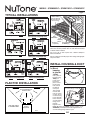
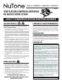
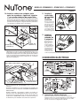
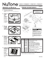
MODELS QTXEN080FLT • QTXEN110FLT • QTXEN150FLT
QTXEN SERIES
FAN / LIGHT / NIGHT LIGHTS
Page 1
READ AND SAVE THESE INSTRUCTIONS
WARNING
CLEANING & MAINTENANCE
TO REDUCE THE RISK OF FIRE, ELECTRIC SHOCK, OR INJURY TO PERSONS, OBSERVE THE FOLLOWING:
1. Usethisunitonlyinthemannerintendedbythemanufacturer.
Ifyouhavequestions,contactthemanufacturerattheaddress
ortelephonenumberlistedinthewarranty.
2. Beforeservicingorcleaningunit,switchpoweroffatservice
panel and lock the service disconnecting means to prevent
powerfrombeingswitchedonaccidentally.Whentheservice
disconnecting means cannot be locked, securely fasten a
prominentwarningdevice,suchasatag,totheservicepanel.
3. Installation work and electrical wiring must be done by a
qualified person(s) in accordance with all applicable codes
and standards, including fire-rated construction codes and
standards.
4. Sufficientairisneededforpropercombustionandexhausting
of gases through the flue (chimney) of fuel burning equipment to prevent backdrafting. Follow the heating equipment
manufacturer’sguidelineandsafetystandardssuchasthose
publishedbytheNationalFireProtectionAssociation(NFPA),
andtheAmericanSocietyforHeating,RefrigerationandAir
ConditioningEngineers(ASHRAE),andthelocalcodeauthorities.
5. When cutting or drilling into wall or ceiling, do not damage
electricalwiringandotherhiddenutilities.
6. Ductedfansmustalwaysbeventedtotheoutdoors.
7. Acceptableforuseoveratuborshowerwhenconnectedto
aGFCI(GroundFaultCircuitInterrupter)-protectedbranch
circuit.
8. Thisunitmustbegrounded.
Forquietandefficientoperation,longlife,andattractiveappearance-lowerorremovegrilleandvacuuminteriorofunitwiththe
dustingbrushattachment.
CAUTION
!
1. Forgeneralventilatinguseonly.Donotusetoexhausthazardousorexplosivematerialsandvapors.
2. This product is designed for installation in ceilings up to a
12/12pitch(45degreeangle).Ductconnectormustpointup.
DONOTMOUNTTHISPRODUCTINAWALL.
3. Toavoidmotorbearingdamageandnoisyand/orunbalanced
impellers,keepdrywallspray,constructiondust,etc.offpower
unit.
4. Pleasereadspecificationlabelonproductforfurtherinformationandrequirements.
Installer: Leave this manual with
the homeowner.
Themotorispermanentlylubricatedandneverneedsoiling.Ifthe
motorbearingsaremakingexcessiveorunusualnoises,replace
theblowerassembly(includesmotorandimpeller).
OPERATION
Thefan,light,andnightlightcanbeoperatedseparately.Usea
3-functionwallcontrol.Donotuseadimmerswitchtooperate
thelight.See“ConnectWiring”fordetails.Useofspeedcontrols
otherthantheNuToneModels78Vand78Wmaycauseamotor
hummingnoise.
WARRANTY
BROAN-NUTONETHREEYEARLIMITEDWARRANTY
Broan-NuTonewarrantstotheoriginalconsumerpurchaserofitsproducts
thatsuchproductswillbefreefromdefectsinmaterialsorworkmanship
foraperiodofthreeyearsfromthedateoforiginalpurchase.THEREARE
NOOTHERWARRANTIES,EXPRESSORIMPLIED,INCLUDING,BUT
NOTLIMITEDTO,IMPLIEDWARRANTIESOFMERCHANTABILITYOR
FITNESSFORAPARTICULARPURPOSE.
During this three-year period, Broan-NuTone will, at its option, repair or
replace,withoutcharge,anyproductorpartwhichisfoundtobedefective
undernormaluseandservice.
THIS WARRANTY DOES NOT EXTEND TO FLUORESCENT LAMP
STARTERS,TUBES,HALOGENANDINCANDESCENTBULBS,FUSES,
FILTERS,DUCTS,ROOFCAPS,WALLCAPSANDOTHERACCESSORIESFORDUCTING.Thiswarrantydoesnotcover(a)normalmaintenance
andserviceor(b)anyproductsorpartswhichhavebeensubjecttomisuse,negligence,accident,impropermaintenanceorrepair(otherthanby
Broan-NuTone),faultyinstallationorinstallationcontrarytorecommended
installationinstructions.
Thedurationofanimpliedwarrantyislimitedtothethree-yearperiodas
specifiedfortheexpresswarranty.Somestatesdonotallowlimitationonhow
longanimpliedwarrantylasts,sotheabovelimitationmaynotapplytoyou.
BROAN-NUTONE’SOBLIGATIONTOREPAIRORREPLACE,ATBROANNUTONE’S OPTION, SHALL BETHE PURCHASER’S SOLEAND EXCLUSIVEREMEDYUNDERTHISWARRANTY.BROAN-NUTONESHALL
NOT BE LIABLE FOR INCIDENTAL, CONSEQUENTIAL OR SPECIAL
DAMAGESARISING OUT OF OR IN CONNECTIONWITH PRODUCT
USE OR PERFORMANCE. Some states do not allow the exclusion or
limitationofincidentalorconsequentialdamages,sotheabovelimitation
maynotapplytoyou.
Thiswarrantygivesyouspecificlegalrights,andyoumayalsohaveother
rights, which vary from state to state.This warranty supersedes all prior
warranties.
To qualifyfor warranty service,you must (a) notify Broan-NuTone at the
addressortelephonenumberstatedbelow,(b)givethemodelnumberand
partidentificationand(c)describethenatureofanydefectintheproductor
part.Atthetimeofrequestingwarrantyservice,youmustpresentevidence
oftheoriginalpurchasedate.
Broan-NuToneLLC,926W.StateStreet,Hartford,Wisconsin53027
www.nutone.com888-336-3948
Register your product online at: www.nutone.com/register
MODELS QTXEN080FLT • QTXEN110FLT • QTXEN150FLT
Page 2
TYPICAL INSTALLATIONS
Housing mounted anywhere between I-joists using hanger bars.
Housing mounted to I-joists.
INSULATION
(Canbeplaced
aroundandover
fanhousing.)
ROOF
CAP*
FAN
HOUSING
6-IN.
ROUND
DUCT*
6-IN.ROUND
*Purchase
separately
ELBOW(S)*
WALL
CAP*
Theunitwilloperatemostquietlyandefficientlywhenlocated
wheretheshortestpossibleductrunandminimumnumber
ofelbowswillbeneeded.
Housing mounted to joists.
Housing mounted anywhere between joists using hanger bars.
Use a roof cap or wall cap that has a built-in damper to
reducebackdrafts.
Plantosupplytheunitwithproperlinevoltageandappropriatepowercable.
INSTALL HOUSING & DUCT
1a. Mount
housing
to joist or
I-joist.
Housing mounted anywhere between trusses using hanger bars.
Housing mounted anywhere between
trusses using hanger bars.
PLAN THE INSTALLATION
COOKING AREA
Do not install above or
inside this area.
45o
NOT FOR USE IN
A COOKING AREA.
45o
Cooking
Equipment
Floor
Useapliersto
bendhousing
TABSout
TABS
to900.Hold
housingin
placesothat
thehousing
tabscontact
thebottom
SPACER
ofthejoist.
(useformountingtoI-Joist)
Thehousing
mountswith
four(4)screws
ornails.Screw
ornailhousing
tojoistthrough
lowestholesin
eachmounting
flange,then
through
I-JOIST
highestholes.
NOTE:MountingtoI-JOIST(shown)requiresuseof
SPACERS(included)betweenthehighestholeof
eachmountingflangeandtheI-joist.
OR
MODELS QTXEN080FLT • QTXEN110FLT • QTXEN150FLT
Page 3
1b. Mount housing anywhere between
trusses, joists, or I-joists using hanger
bars.
Slidinghangerbarsareprovidedtoallowforaccuratepositioningofhousinganywherebetweenframing.Theycanbe
usedonalltypesofframing(I-joist,standardjoist,andtruss
construction)andspanupto24”.
2. Attach
damper/duct
connector.
Snapdamper/
ductconnector
ontohousing.
Makesureconnectorisflushwith
topofhousingand
damperflapfalls
closed.
TAB
SCREWS(4)
3. Install
6-inch
round ductwork.
ST
D
Connect6-inch
roundductwork
todamper/duct
connector.Run
ductworktoa
roofcaporwall
cap.Tapeall
ductworkconnectionstomake
themsecureandairtight.
MOUNTING
CHANNEL(2)
HANGER
BAR(4)
Attach the MOUNTING CHANNELS to the housing using
theSCREWSsupplied.MakesureTABSface“up”asshown.
Usethesetofchannelmountingholes(marked“STD”)to
mountthehousingflushwiththebottomofthedrywall.Use
the other set of holes (not marked) to mount the housing
flushwiththetopofthedrywall.
HOLEFOROPTIONAL
SCREWMOUNTING(4)
NAIL(4)
CONNECT WIRING
*SCREW(2)
BOTTOMEDGE
OFFRAMING
ExtendHANGERBARStothewidthoftheframing.
Hold ventilator in place with the hanger bar tabs wrapping
aroundtheBOTTOMEDGEOFTHEFRAMING.
NAILventilatortoframingorfastenwithscrews(notprovided)
throughHOLESnearnails.
Toensureanoise-freemount:Securehangerbarstogether
*with
SCREWS or use a pliers to crimp mounting channels
tightlyaroundhangerbars.
4. Connect electrical wiring.
Run120VAChousewiringtoinstallationlocation.Use
properULapprovedconnectortosecurehousewiringto
wiringplate.Connectwiresasshowninwiringdiagrams.
MODELS QTXEN080FLT • QTXEN110FLT • QTXEN150FLT
Page 4
INSTALL GRILLE
SERVICE PARTS
Replacement parts can be ordered on our website. Please
visit us at www.nutone.com
5. Finish ceiling.
Installceilingmaterial.Cutoutaroundhousing.
6. Attach
grille to
housing.
Squeeze
grillesprings
andinsert
theminto
tabsoneach
sideofhousing.
7. Push
grille
against
ceiling.
SERVICE NOTEToremoveBlower
Assembly:Unplugmotor.Remove
thumbscrew(11)frommotorplate
flange.FindthesingleTABon
themotorplate(locatednextto
thereceptacle).Pushupnear
motorplatetabwhilepushingout
onsideofhousing.Orinserta
straight-bladescrewdriverintoslot
inhousing(nexttotab)andtwist
screwdriver.
8. Remove
light
lens.
Carefullyinsertasmall
flat-blade
screwdriver
between
grilleand
lens.Pry
lensout.
9. Install
light
bulbs.
Fluorescentbulbs
supplied.
Purchasea
4Wincandescent
night-light
bulb.Insert
bulbsinto
theirsockets.Replacelens.
Key No. Part No.
1
2
3
4
5
6
7
8
9
10
11
12
13
97016466
97016450
98010102
99170245
97018011
97017850
97017851
97016591
97018272
99140199
99111400
99271381
99420665
97018014
QTNHB1
Description
Housing
DuctConnector-6”
WiringPlate
Screw,#8-18X.375
WirePanel/HarnessAssembly
BlowerAssembly(QTXEN080FLT)
BlowerAssembly(QTXEN110FLT)
BlowerAssembly(QTXEN150FLT)
GrilleAssembly(includeskeynos.8,9&10)
GrilleSpring(2req’d)
Lens
Bulb,GU24,18WFluorescent,(2req’d)
Thumbscrew,#8-18x.375
Spacer(2supplied)
HangerBarKit
Orderservicepartsby“PartNo.”-notby“KeyNo.”
99044460A
MODELOS QTXEN080FLT • QTXEN110FLT • QTXEN150FLT
Página 5
VENTILADOR/LÁMPARA/LÁMPARAS
DE NOCHE SERIE QTXEN
LEA Y CONSERVE ESTAS INSTRUCCIONES
ADVERTENCIA
LIMPIEZA Y MANTENIMIENTO
PARA REDUCIR EL RIESGO DE INCENDIOS, DESCARGAS
ELÉCTRICAS O LESIONES PERSONALES, OBSERVE LAS
SIGUIENTES PRECAUCIONES:
1. Use la unidad sólo de la manera indicada por el fabricante. Si
tienepreguntas,comuníqueseconelfabricanteenladireccióno
elnúmerotelefónicoqueseincluyeenlagarantía.
2.Antes de dar servicio a la unidad o de limpiarla, interrumpa el
suministroeléctricoenelpaneldeservicioybloqueelosmedios
de desconexión del servicio para evitar que la electricidad se
reanude accidentalmente. Cuando no sea posible bloquear los
mediosdedesconexióndelservicio,fijefirmementeunaseñalde
advertencia(talcomounaetiqueta)enunlugarvisibledelpanel
deservicio.
3.Eltrabajodeinstalaciónyelcableadoeléctricodebenestaracargo
deunpersonalcapacitadoydebensatisfacertodosloscódigos
ynormascorrespondientes,incluidosloscódigosynormasde
construcciónespecíficossobreproteccióncontraincendios.
4.Se necesita suficiente aire para que se lleve a cabo una combustiónydescargaadecuadasdelosgasesatravésdeltubode
humos(chimenea)delequipoquemadordecombustible,afinde
evitarloscontratiros.Sigalasdirectricesylasnormasdeseguridad
delfabricantedelequipodecalentamiento,comolaspublicadas
porlaAsociaciónNacionaldeProteccióncontraIncendios(NationalFireProtectionAssociation,NFPA),laSociedadAmericana
deIngenierosdeCalefacción,RefrigeraciónyAireAcondicionado
(AmericanSocietyforHeating,RefrigerationandAirConditioning
Engineers,ASHRAE)ylasautoridadesdeloscódigoslocales.
5. Al cortar o perforar a través de la pared o del cielo raso, no dañe
el cableado eléctrico ni otros servicios ocultos.
6.Losventiladoresconconductosdebensiempreconectarsehacia
elexterior.
7. Esta unidad puede instalarse sobre una tina o ducha siempre
queseconecteaunGFCI(interruptoraccionadoporpérdidade
conexiónatierra)enuncircuitodederivaciónprotegido.
8.Estaunidaddebeconectarseatierra.
Paralograrunfuncionamientosilenciosoyeficiente,comotambién
largavidayunaaparienciaatractiva,bajeoretirelarejillayaspireel
interiordelaunidadconelaccesoriodelcepilloparasacudirpolvo.
PRECAUCIÓN
!
1. Sóloparausarsecomomediodeventilacióngeneral.Noseuse
paradescargarmaterialesnivaporespeligrososoexplosivos.
2. Esteproductosediseñaparalainstalaciónentechoshastauna
echadade12/12(ángulode45grados).Conectordeconductor
debeseñalarhaciaarriba.NOMONTEESTEPRODUCTOEN
UNATECHO.
3. Para evitar daños a los cojinetes del motor y rotores ruidosos y/o no
equilibrados, mantenga la unidad de accionamiento al resguardo
de rociados de yeso, polvos de construcción, etc.
4. Léaselaetiquetadeespecificacionesquetieneelproductopara
verinformaciónyrequisitosadicionales.
A la persona que realiza la
instalación: Deje este manual con el
dueño de la casa.
Elmotorestápermanentementelubricadoynuncanecesitaráaceite.
Siloscojinetesdelmotorestánhaciendoruidoexcesivooinusitado,
reemplace el conjunto del ventilador (incluye el motor y el rodete
delventilador).
OPERACIÓN
Elventilador,lalámparaylalámparadenochepuedenfuncionar
separadamente.Utiliceuncontroldeparedde3funciones.Noutilice
uninterruptorreguladorparafuncionarlaluz.Vealosdetallesenla
sección“Conexióneléctrica”.Elusodeloscontrolesdelavelocidad
conexcepcióndelosmodelos78Vy78WdeNuTonepuedecausar
unruidodeltarareodelmotor.
GARANTÍA
GARANTÍALIMITADADETRESAÑOSDEBROAN-NUTONE
Broan-NuTone garantiza al consumidor comprador original que sus productos
estaránlibresdedefectosencuantoamaterialymanodeobraduranteunperíodo
de tres años a partir de la fecha de la compra original. NO EXISTEN OTRAS
GARANTÍAS,EXPRESASNIIMPLÍCITAS,INCLUIDAS(PEROSINLIMITARSE
A)GARANTÍASIMPLÍCITASDECOMERCIALIZACIÓNOIDONEIDADPARAUN
PROPÓSITOPARTICULAR.
Duranteesteperíododetresaños,Broan-NuTone,asucriterio,repararáoreemplazará,sincargoalguno,cualquierpiezaoproductoqueseencuentredefectuoso
bajocondicionesnormalesdeusoyservicio.
LA PRESENTE GARANTÍA NO CUBRE LOS TUBOS FLUORESCENTES NI
SUSARRANCADORES,BOMBILLASDEHALÓGENOEINCANDESCENTES,
FUSIBLES, FILTROS, CONDUCTOS, TAPONES DE TECHO O PAREDES Y
DEMÁSACCESORIOSPARACONDUCTOS.Estagarantíanocubre(a)mantenimientooservicionormalesni(b)productosopiezasquesehayansometidoa
usoinadecuado,negligencia,accidente,mantenimientooreparacióninadecuada
(nohechaporBroan-NuTone),instalaciónincorrectaoinstalaciónencontradelas
instruccionesdeinstalaciónrecomendadas.
Laduracióndeunagarantíaimplícitaselimitaalperíododetresaños,comose
especificaparalagarantíaexplícita.Algunosestadosnopermitenlimitarladuración
deunagarantíaimplícita,demaneraquelaslimitacionesantedichaspodríanno
aplicarseausted.
LAOBLIGACIÓNDEBROAN-NUTONEDEREPARAROREEMPLAZAR,AOPCIÓNDEBROAN-NUTONE,SERÁELÚNICOYEXCLUSIVORECURSODEL
COMPRADORBAJOESTAGARANTÍA.BROAN-NUTONENOSERÁRESPONSABLE POR DAÑOS INCIDENTALES, RESULTANTES O ESPECIALES QUE
SURJANDE,OENRELACIÓNCON,ELUSOORENDIMIENTODELPRODUCTO.
Algunosestadosnopermitenexcluirolimitardañosincidentalesoresultantes,de
maneraqueesposiblequelalimitaciónantedichanoseapliqueensucaso.
Estagarantíaledaderechoslegalesespecíficos;ustedpodríatenerotrosderechos
quevaríanentreestados.Estagarantíasustituyetodaslasgarantíasanteriores.
Para tener derecho al servicio de la garantía, usted debe (a) notificar a
Broan-NuTone a la dirección y número de teléfono que aparecen abajo,
(b) proporcionar el número de modelo y la identificación de la pieza y
(c) describir la naturaleza de cualquier defecto en el producto o pieza. E n e l m o m e n to d e s o l i c i t a r e l s e r v i c i o d e l a ga r a n t í a , d e b e presentarelcomprobanteconlafechadelacompraoriginal.
Broan-NuToneLLC,926W.StateStreet,Hartford,Wisconsin53027
www.nutone.com888-336-3948
Para registrar este producto visite: www.nutone.com/register
MODELOS QTXEN080FLT • QTXEN110FLT • QTXEN150FLT
Página 6
INSTALACIONES TÍPICAS
Montaje de la cubierta en viguetas
“I”.
Montaje de cubierta en viguetas.
Montaje de la cubierta en cualquier parte entre las viguetas “I” por
medio de barras de suspensión.
Montaje de la cubierta en cualquier
parte entre las viguetas por medio
de barras de suspensión.
AISLAMIENTO
(Puede ser colocado
alrededor y sobre
de la cubierta del
ventilador.)
TAPA DE
TECHO *
CUBIERTA DE
VENTILADOR
CONDUCTO
REDONDO DE
6 PULG. *
CODO REDONDO
* Se compran
DE 6 PULG. *
por separado
TAPA
DE
PARED *
Elventiladorfuncionaráconmáseficienciaymenosruidosise
ubicaenunsitiodonderequieraeltramodeconductomáscorto
posibleyunmínimonúmerodecodos.
Instaleunatapadetechoodeparedquetengaunreguladorde
tiroincorporadoafindereducirloscontratiros.
Alimentelaunidadconelvoltajedelíneayelcableeléctrico
apropiados.
INSTALE LA CUBIERTA Y
EL CONDUCTO
1a. Instale
Montaje de la cubierta en cualquier
parte entre armaduras por medio
de barras de suspensión.
Montaje de la cubierta en cualquier
parte entre armaduras por medio
de barras de suspensión.
PLANIFICACIÓN DE LA
INSTALACIÓN
ÁREA QUE COCINA
No instale sobre o dentro
de esta área.
45o
NO PARA EL
USO EN UN
ÁREA QUE COCINA.
45o
Equipo
para cocinar
Piso
la
cubierta en
las viguetas
o viguetas
“I”.
Conunalicate,
LENGÜETAS
doblelas
LENGÜETAS
delacubiertaa
90°.Sostenga
lacubiertaen
SEPARADOR(seusapara
sulugarde
elmontajealavigueta“I”)
maneraquelas
lengüetasdela
cubiertahagan
contactoconla
parteinferiorde
lavigueta.Para
elmontajede
lacubiertase
utilizancuatro(4)
tornillosoclavos.
Atornilleoclave
VIGUETA “I”
lacubiertaala
viguetaatravés
delosorificiosmásbajosdecadabridademontaje,y
seguidamenteatravésdelosmásaltos.NOTA:Para
elmontajeenlaVIGUETA “I”,talcomoseilustra,se
requiereutilizarSEPARADORES(incluidos)entreel
orificiomásaltodecadabridademontajeylavigueta“I”.
O BIEN
MODELOS QTXEN080FLT • QTXEN110FLT • QTXEN150FLT
Página 7
1b. Instale la cubierta en cualquier parte
entre las armaduras, viguetas o viguetas
“I” por medio de barras de suspensión.
Seproporcionanbarrasdesuspensióndeslizantesparafacilitar
lacolocaciónadecuadadelacubiertaencualquierparteentrela
estructura.Estasbarrasseadaptanatodaclasedeestructuras
(construccionesdeviguetas“I”,viguetasestándaryarmaduras)
y seextiendenaunmáximode61cm(24pulg.).
2. Acople el
conectador
del regulador
de tiro/
conducto.
Conecteapresiónel
conectadordelreguladordetiro/conductoenlacubierta.
Asegúresedequeel
conectorestéalras
conlapartesuperior
delacubiertayque
laaletadelreguladorcaigacerrada.
LENGÜETA
TORNILLOS(4)
ST
D
3. Instale el
conducto
redondo de
6 pulgadas.
CANALDE
MONTAJE(2)
BARRADESUSPENSIÓN(4)
FijelosCANALESDEMONTAJEalacubiertaconlosTORNILLOSincluidos.AsegúresedequelasLENGÜETASesténdecara
haciaarriba,talcomosemuestra.Utiliceeljuegodeorificiosde
montajedelcanal(marcadoscomo“STD”)paramontarlacubierta
alrasconlaparteinferiordelatablarroca.Utiliceelotrojuegode
orificios(sinmarca)paramontarlacubiertaalrasconlaparte
superiordelatablarroca.
ORIFICIOPARAMONTAJE
CONTORNILLOOPCIONAL(4)
CLAVO(4)
CONEXIÓN ELÉCTRICA
*TORNILLO(2)
BORDEINFERIORDE
LAESTRUCTURA
Abra las BARRAS DE SUSPENSIÓN hasta el ancho de la
estructura.
Sostengaelventiladorensusitioenvolviendolaslengüetasde
labarradesuspensiónalrededordelBORDEINFERIORDELA
ESTRUCTURA.
CLAVEelventiladoralaestructuraosujételocontornillos(no
incluidos)atravésdelosORIFICIOSqueestáncercadelosclavos.
Paralograrunmontajesilencioso:acopleyfijelasbarrasde
suspensiónconTORNILLOS,odobleloscanalesdemontajecon
unalicatebienjustosalrededordelasbarrasdesuspensión.
*
Conecteelconductoredondode
6pulg.alconectordelregulador/
conducto.Extienda
elconductohacia
unatapadetecho
otapadepared.
Encintetodaslas
conexionesdelos
conductosparafijarlasyhacerlasherméticasalaire.
4. Conecte los cables eléctricos.
Extiendaelcableadodelacasade120VCAallugardela
instalación.UtiliceunaconexiónaprobadaporULparaafianzarel
cableadodelacasaalaplacadecableado.Conecteloscables
talcomoseilustraenlosdiagramasdecableado.
MODELOS QTXEN080FLT • QTXEN110FLT • QTXEN150FLT
Página 8
INSTALE LA REJILLA
PIEZAS DE REPUESTO
5. Termine el cielo raso.
Las piezas de recambio se
pueden ahora pedir en nuestro
Web site. Visítenos por favor en
www.nutone.com
Instaleelmaterialdelcieloraso.Recortealrededordela
cubierta.
6. Acople la
rejilla
a la
cubierta.
Aprietelos
resortesdela
rejillaeinsértelosenlas
lengüetasque
seencuentran
acadaladode
lacubierta.
7. Empuje
la rejilla
contra el
cielo raso.
NOTA DE SERVICIO Para desmontar el
conjunto del ventilador: Desenchufe el
motor. Saque el tornillo de mariposa (11)
de la brida de la placa del motor. Localice
la LENGÜETA única de la placa del motor
(se encuentra junto al receptáculo).
Empuje hacia arriba cerca de la lengüeta
de la placa del motor al mismo tiempo
que empuja hacia afuera el costado
de la cubierta. O bien, introduzca un
destornillador de punta recta en la ranura
de la cubierta (junto a la lengüeta) y
gírelo.
8. Saque la
lente de la
lámpara.
Concuidado,
inserteun
destornillador
planopequeño
entrelaparillaylalentede
lámpara.Haga
palancaconel
destornilladorysaquelalente.
9. Instale las
bombillas.
Seincluyelas
bombillas
fluorescentes.
Compreuna
bombilla
denoche
incandescente
de4W.Inserte
lasbombillasa
sureceptáculos.
Vuelvaacolocar
lalente.
Clave n.o
Pieza n.o
1
2
3
4
5
6
7
97016466
97016450
98010102
99170245
97018011
97017850
97017851
97016591
97018272
8
9
10
11
12
13
Descripción
Cubierta
Conectordeconductor,6pulg.
Placadecableado
Tornillon.o8-18x0.375
Conjuntodelpaneldecableado/arnés
Conjuntodelventilador(QTXEN080FLT)
Conjuntodelventilador(QTXEN110FLT)
Conjuntodelventilador(QTXEN150FLT)
Conjuntodelarejilla
(incluyenlaspiezasdelasclavesn.o8,9&10)
99140199 Resortedelarejilla(serequieren2)
99111400
Lente
99271381 Bombillafluorescente,GU24,18W(serequieren2)
99420665 Tornillodemariposan.o8-18x0.375
97018014 Separador(provisto2)
QTNHB1
Juegodebarradesuspención
Alhacerelpedidodeunapiezadeserviciosedebeespecificarel
númerodelapieza(noelnúmerodelaclave).
99044460A