1
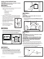
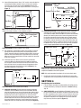
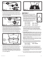
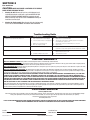
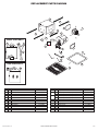
IMPORTANT INSTRUCTIONS OPERATING MANUAL
Models:ES80SG, ES130SG,
ES80DG, ES130DG
Exhaust Fan
READ AND SAVE THESE INSTRUCTIONS
READ CAREFULLY BEFORE ATTEMPTING TO ASSEMBLE, INSTALL, OPERATE OR MAINTAIN THE PRODUCT DESCRIBED.
PROTECT YOURSELF AND OTHERS BY OBSERVING ALL SAFETY INFORMATION. FAILURE TO COMPLY WITH
INSTRUCTIONS COULD RESULT IN PERSONAL INJURY AND/OR PROPERTY DAMAGE!
RETAIN INSTRUCTIONS FOR FUTURE REFERENCE.
GENERAL SAFETY INFORMATION
When using electrical appliances, basic precautions
should always be followed to reduce the risk of fire,
electric shock and injury to person, including the following:
TO REDUCE THE RISK OF FIRE, ELECTRIC SHOCK AND INJURY TO
PERSON, OBSERVE THE FOLLOWING:
a) Use this unit only in the manner intended by the manufacturer.If
you have questions, contact the manufacturer.
b) Before servicing or cleaning the unit, switch power off at service
panel and lock the service disconnecting means to prevent
power from being switched on accidentally. When the service
disconnecting means cannot be locked, securely fasten a
prominent warning device, such as a tag, to the service panel.
TO REDUCE THE RISK OF FIRE, ELECTRIC SHOCK AND INJURY TO
PERSON, OBSERVE THE FOLLOWING:
a) Installation work and electrical wiring must be done by qualified
person(s) in accordance with all applicable codes and standards,
including fire-related construction.
b) Sufficient air is needed for proper combustion and exhausting
of gases through the flue (chimney) of fuel burning equipment
to prevent back drafting. Follow the heating equipment
manufacturer’s guideline and safety standards such as those
published by the National Fire Protection Association (NFPA)
and the American Society for Heating, Refrigeration, and Air
Conditioning Engineers (ASHRAE), and the local code authorities.
d) Ducted fans must always be vented to the outdoors.
e) If this unit is to be installed over a tub or shower, it must be
marked as appropriate for the application and be connected to a
GFCI (Ground Fault Circuit Interrupter) - protected branch circuit.
f) This unit must be grounded.
g) To avoid motor bearing damage and noisy and/or unbalanced
impellers, keep drywall spray, construction dust, etc. off power unit.
h) NEVER place a switch where it can be reached from a tub or
shower.
i) Suitable for use with electronic speed control device.
j) Do not install into ceilings thermally insulated to a value greater
than R40.
CAUTION: FOR GENERAL VENTILATING USE ONLY. DO NOT
USE TO EXHAUST HAZARDOUS OR EXPLOSIVE MATERIALS AND
VAPORS.
WARNING: DO NOT USE IN KITCHENS.
k) Read all instructions before installing or using exhaust fan.
c) When cutting or drilling into wall or ceiling, do not damage
electrical wiring and other hidden utilities.
SAVE THESE INSTRUCTIONS
A210572215 Rev. B 5-12
www.airkinglimited.com
1 of 12
INSTALLATION INSTRUCTIONS
CAUTION: MAKE SURE POWER IS SWITCHED OFF AT SERVICE
PANEL BEFORE STARTING INSTALLATION.
SECTION 1
Preparing the Exhaust Fan
1. Unpack fan from the carton and confirm that all pieces are present. In
addition to the exhaust fan you should have:
1 - Grill
1 - Damper Assembly (attached)
4 - Mounting Rails
1 - Mounting Flange
1 - Instruction/Safety Sheet
2. Choose the location for your fan. To ensure the best air and sound
performance, it is recommended that the length of ducting and the
number of elbows be kept to a minimum, and that insulated hard
ducting be used. Larger duct sizes will
reduce noise and airflow restrictions. This
fan will require at least 10" of clearance in
the ceiling or wall, and will mount through
drywall up to 3/4" thick.
Joist
Figure 3
SECTION 4
Ducting
CAUTION:
ALL DUCTING MUST COMPLY WITH LOCAL AND
NATIONAL BUILDING CODES.
1. Connect the ducting to the fan’s duct collar (Figure 4). Secure in place
using tape or screw clamp. Always duct the fan to the outside through
a wall or roof cap.
Ducting
3. Select the most convenient electrical
knockout and remove using a straightblade screw driver (Figure 1).
Duct
Collar
Figure 1
SECTION 2
New Construction
1. Install the rails on the housing and position the housing next to the
joist. Line up housing so that it will be flush with the finished ceiling.
Secure the ends of the rails with screws or nails (not included) to the
joists and slide the housing into the final position (Figure 2).
Figure 4
SECTION 5
Wiring
CAUTION: MAKE SURE POWER IS SWITCHED OFF AT SERVICE
PANEL BEFORE STARTING INSTALLATION.
CAUTION: ALL ELECTRICAL CONNECTIONS MUST BE MADE
IN ACCORDANCE WITH LOCAL CODES, ORDINANCES, OR NATIONAL
ELECTRICAL CODE. IF YOU ARE UNFAMILIAR WITH METHODS OF
INSTALLING ELECTRICAL WIRING, SECURE THE SERVICES OF A
QUALIFIED ELECTRICIAN.
Housing
Joist
Figure 2
SECTION 3
Mounting Rails
NOTE: This unit includes a side access panel for wiring that does not
require the removal of the fan’s blower assembly. If you choose to wire
the unit from the inside, you will need to remove the blower assembly and
internal wiring compartment. Both methods are equally effective.
1a. External Wire Compartment: Remove the wire compartment cover
screw and place cover in a secure place (Figure 5).
Existing Construction
1. Set housing in position between the joist and trace an outline onto
the ceiling material (Figure 3). Set housing aside and cut opening,
being careful not to cut or damage any electrical or other hidden
utilities. Install the rails on the housing and position the housing in the
previously cut hole so that it is flush with the finished ceiling. Secure
the ends of the rails to the joists (Figure 3).
Screw
Wire
Compartment
Cover
Figure 5
A210572215 Rev. B 5-12
www.airkinglimited.com
2 of 12
1b. Internal Wire Compartment: Using a 7/16" socket, remove the two hex
nuts holding the blower assembly in place. Lift up on the assembly
and slide it out of the tabs on the housing (Figure 6). Remove the
wire compartment cover screw and place the cover in a secure place
(Figure 7).
Supply from
house
Hot (Black)
Neutral
(White)
Ground (Green or Bare)
Plug
Black
Tabs
Yellow
Hex Nuts
Figure 6
NOTE: If the fan motor plug is connected to the fan housing receptacle,
unplug so the blower assembly can be completely removed.
Wire Compartment
Cover
Screw
Figure 7
NOTE: Wire compartment configuration will be dependent on model.
SINGLE SPEED UNITS (models ES80SG and ES130SG)
2a. Run wiring from an approved wall switch (not included) carrying the
appropriate rating. One neutral (white), one ground (green or bare
copper), and one hot (black lead connected to the switch). Secure the
electrical wires to the housing with an approved electrical connector.
Make sure you leave enough wiring in the box to make the connection
to the fan’s receptacle.
2b. From where you have chosen to access the fan’s junction box,
connect the white wire from the house to the white wire from the
fan’s receptacle. Connect the black wire from the wall switch to the
black wire from the fan’s receptacle. Connect the ground wire from
the house to the green wire from the fan housing (Figure 8). Use
approved methods for all connections.
Supply from
house
Ground
Figure 8
Switch
Figure 9
3b. Intermittent Ventilation: For two speed fans wired for intermittent
ventilation with a standard duplex toggle switch (such as Leviton
5224-2W not included). Connect the White wire of the fan to the White
(Neutral) wire from the power source. Connect the ground wire from
the fan to the ground wire from the power source. Properly ground
the switches. Connect the black wire from the supply to one side of
the top switch. Connect the black wire from the fan to the other side
of the top switch, Connect 1 yellow wire from the fan to each side of
the bottom switch. The top switch turns the fan On & Off, the bottom
switch changes speed between high and low (Figure 10).
Supply from house
Neutral (White)
Ground (Green or Bare)
Hot
(Black)
Black
Switch
Figure 10
Fan
Yellow
Yellow
NOTE: The fan’s receptacle wires might need to be pulled outside
compartment for connection. Only pull the five loose wires outside of
compartment. Additional wires will be present.
NOTE: Unit must be grounded according to all local and national codes.
4. Carefully tuck wire back inside wire compartment and replace wire
compartment cover securing with the screw that was removed earlier.
White
Hot (Black)
TWO SPEED UNITS (models ES80DG and ES130DG)
3a. Continuous Ventilation: For two speed fans wired for continuous
ventilation, connect the White wire of the fan to the White (Neutral)
wire from the power source. Connect the ground wire from the house
to the green wire from the fan housing. Run 2 wires from a properly
grounded wall switch (not included) to the fan. Connect the Black
wire of the fan to the Black wire (Hot) from the power source. Connect
the Hot Yellow wire from the fan to the input of the switch. Connect
the second Yellow wire from the fan to the output side of the switch.
Closing the switch will change from normal to high speed (Figure 9).
A210572215 Rev. B 5-12
Yellow
SECTION 6
Completing the Installation
1. If the fan’s blower assembly was removed during the wiring process,
reinstall the blower by reversing the directions in Section 4 (Wiring),
Step 1b.
2a. SINGE SPEED UNITS (models ES80SG and ES130SG): Plug the fan’s 2
pin quick connect motor cord into the receptacle located on the side of
the wire compartment cover. Plug the 3 pin quick connect motor cord
into the shorter end of the included harness then into the receptacle
located on the top of the wire compartment cover These cords will
only fit one way into the receptacles (Figure 11).
www.airkinglimited.com
3 of 12
From
Sensor
From
Motor
Figure 11
From
Motor
Figure 14
2b. TWO SPEED UNITS (models ES80DG and ES130DG): Plug the fan’s 2
pin and 3 pin quick connect motor cords into the receptacles located
on the side of the wire compartment. Plug the 3 pin quick connect
cord from the motion sensor on the grill into the receptacle coming out
of the top of the wire compartment. These cords will only fit one way
into the receptacles (Figure 12).
From
Sensor
From Motor
Figure 12
From Motor
3. Install the ceiling mounting flange to cover any gaps which exist
between the housing and the finished ceiling. Line up the slots in the
ceiling mounting flange with the screws on the inside of the housing and
press flange in place so it is tight against the ceiling. Tighten both screws
inside the housing. Install drywall screws (not included) through the
holes in the flange and into the ceiling. Install as many drywall screws
needed to ensure the flange fits tightly against the ceiling (Figure 13).
Screws
Ceiling
Mounting
Flange
Figure 13
Slots
Drywall Screw
4. Install the grill by squeezing the spring furthest from the motion
sensor together and installing it up into the slot furthest from the wire
compartment on the fan’s housing. Attach the 3 pin quick connect
from the motion sensor on the grill to either the harness installed in
Step 2a (Single Speed Models) or the connector from the top of the
wire compartment (Two Speed Models). This cord will only fit one way
into the receptacle. Install the other spring in place and push the grill
up into position (Figure 14).
A210572215 Rev. B 5-12
5. Restore power and test your installation.
SECTION 7
Programming the Occupancy Sensor
1a. Setting the Occupancy Time Delay. This will set
the amount of time the fan will continue to operate
after the room is vacated or on dual speed models
the amount of time the fan will run on high speed.
Locate the motion sensor on the fan’s grill and
press the button 2 times. The LED on the sensor
will then flash the number of times to indicate the
current setting, this will repeat 3 times:
1 time = 30 seconds
2 times = 2.5 minutes
6 times = 12.5 minutes
3 times = 5 minutes 7 times = 15 minutes
4 times = 7.5 minutes 8 times = 17.5 minutes
5 times = 10 minutes 9 times = 20 minutes
1b. To adjust the setting, while the sensor is still flashing from Step 1a,
press the button the number of times that corresponds with the
amount of time you desire, for instance 3 times sets the delay to
5 minutes (see numbers in Step 1). The sensor will then flash the
number of times for the new setting 3 times before exiting back to the
programming mode.
2a Setting the Minimum On Time. This sets the minimum time the fan
will operate once motion is detected within the room or on dual speed
models the amount of time the fan will run on high speed. This works
in conjunction with the Occupancy Time Delay feature set in Steps 1a
and 1b. For instance if you set the minimum time on for 15 minutes
and the Time Delay for 5 minutes, the fan will operate for at least 15
minutes then 5 additional minutes.
NOTE: This is a minimum time that the fan will operate. If the room is
occupied longer, the fan will continue to run until the room is vacated
and the occupancy time delay has elapsed.
2b. Locate the motion sensor on the fan’s grill and press the button 10
times. The LED on the sensor will then flash the number of times to
indicate the current setting, this will repeat 3 times:
1 time = 0 minutes
4 times = 45 minutes
2 times = 15 minutes
5 times = 60 minutes
3 times = 30 minutes
2c. To adjust the setting, while the sensor is still flashing from Step 2b,
press the button the number of times that corresponds with the
amount of time you desire, for instance 3 times sets the minimum on
time to 30 minutes (see numbers in Step 2b). The sensor will then flash
the number of times for the new setting 3 times before exiting back to
the programming mode.
3. Once all setting have been made and the sensor will return to detection
mode and the LED will flash when occupancy of the room is detected.
www.airkinglimited.com
4 of 12
SECTION 8
Use and Care
CAUTION: MAKE SURE POWER IS SWITCHED OFF AT SERVICE
PANEL BEFORE SERVICING THE UNIT.
1. Cleaning the Grill: Remove grill and use a mild detergent, such
as dishwashing liquid, and dry with a soft cloth. NEVER USE ANY
ABRASIVE PADS OR SCOURING POWDERS. Completely dry grill
before reinstalling. Refer to instructions in Section 5 Finishing the
Installation, to reinstall grill.
2. Cleaning the Fan Assembly: Wipe all parts with a dry cloth or gently
vacuum the fan. NEVER IMMERSE ELECTRICAL PARTS IN WATER.
Troubleshooting Guide
Trouble
Probable Cause
Suggested Remedy
1. Fan does not operate when the switch is on.
1a. A fuse may be blown or a circuit tripped.
1a.
1b. Connector plug from motor is not plugged in. 1b.
1c. Wiring is not connected properly.
1c.
1d Motor has stopped operating.
1d.
Replace fuse or reset circuit breaker.
Turn off power to unit. Remove Grill and plug motor into receptacle
in housing. Restore power to unit.
Turn off power to unit. Check that all wires are connected.
Replace motor.
2. Fan is operating, but air moves slower than normal.
2. Obstruction in the exhaust ducting.
2.
Check for any obstructions in the ducting. The most common are bird
nests in the roof cap or wall cap where the fan exhausts to the outside.
3. Fan is operating louder than normal
3a. Motor is loose.
3a. Turn off power to unit. Remove grill and check that all screws are fully
tightened. Restore power to unit.
3b. Fan blade is hitting housing of unit.
3b. Call your dealer for service.
LIMITED WARRANTY
WHAT THIS WARRANTY COVERS: This product is warranted against defects in workmanship and/or materials.
HOW LONG THIS WARRANTY LASTS: This warranty extends only to the original purchaser of the product and lasts for five (5) years from the date of original purchase
or until the original purchaser of the product sells or transfers the product, whichever first occurs.
WHAT AIR KING WILL DO: During the warranty period, Air King will, at its sole option, repair or replace any part or parts that prove to be defective or replace the whole
product with the same or comparable model.
WHAT THIS WARRANTY DOES NOT COVER: This warranty does not apply if the product was damaged or failed because of accident, improper handling or operation,
shipping damage, abuse, misuse, unauthorized repairs made or attempted. This warranty does not cover shipping costs for the return of products to Air King for repair or
replacement. Air King will pay return shipping charges from Air King following warranty repairs or replacement
ANY AND ALL WARRANTIES, EXPRESSED OR IMPLIED (INCLUDING, WITHOUT LIMITATION, ANY IMPLIED WARRANTY OF MERCHANTABILITY), LAST ONE YEAR
FROM THE DATE OF ORIGINAL PURCHASE OR UNTIL THE ORIGINAL PURCHASER OF THE PRODUCT SELLS OR TRANSFERS THE PRODUCT, WHICHEVER FIRST
OCCURS AND IN NO EVENT SHALL AIR KING’S LIABILITY UNDER ANY EXPRESS OR IMPLIED WARRANTY INCLUDE (I) INCIDENTAL OR CONSEQUENTIAL DAMAGES
FROM ANY CAUSE WHATSOEVER, OR (II) REPLACMENT OR REPAIR OF ANY HOUSE FUSES, CIRCUIT BREAKERS OR RECEPTACLES. NOTWITHSTANDING ANYTHING TO
THE CONTRARY, IN NO EVENT SHALL AIR KING’S LIABILITY UNDER ANY EXPRESS OR IMPLIED WARRANTY EXCEED THE PURCHASE PRICE OF THE PRODUCT
AND ANY SUCH LIABILITY SHALL TERMINATE UPON THE EXPIRATION OF THE WARRANTY PERIOD.
Some states and provinces do not allow limitations on how long an implied warranty lasts, or the exclusion or limitation of incidental or consequential damages, so these
exclusions or limitations may not apply to you. This warranty gives you specific legal rights. You may also have other rights which vary from state to state and province to
province. Proof of purchase is required before a warranty claim will be accepted.
CUSTOMER SERVICE:
Toll-Free (800) 465-7300
Our Customer Service team is available to assist you with product questions, service center locations, and replacement parts. They can be reached Monday through
Friday, 8am-4pm Eastern. Please have your model number available, as well as the type and style (located on the label inside of your product).
Please do not return product to place of purchase.
www.airkinglimited.com
PARTS FOR DISCONTINUED, OBSOLETE AND CERTAIN OTHER PRODUCTS MAY NOT BE AVAILABLE. DUE TO SAFETY REASONS, MANY ELECTRONIC COMPONENTS
AND MOST HEATER COMPONENTS ARE NOT AVAILABLE TO CONSUMERS FOR INSTALLATION OR REPLACEMENT.
Installer:
Installation Date:
Place of Purchase:
Model Number:
A210572215 Rev. B 5-12
www.airkinglimited.com
5 of 12
REPLACEMENT PARTS DIAGRAM
1
2
6
5
20
SINGLE SPEED UNITS
3
21
2
13
4
12
14-15
14
16
7
11
22
17
10
19
9
DUAL SPEED UNITS
18
8
15
# Qty.
1
1
2
4
3
1
4
1
5 4
6
1
7
1
8 1
9
2
10
2
11 2
12 1
A210572215 Rev. B 5-12
Description
Fan Housing
Mounting Rails
Blower Assembly
6” Metal Collar Assembly
Screws
Collar Gasket
Outlet Gasket
Grill
Grill Springs
Flange Nut
Grommets
#10 Ground Screw
Replacement Part #
5S1239009
5S1299002
5S2239008
5S5299100
5S1999010
5S1202054
5S1202053
5S1239015
5S1202046
5S1202031
5S1202032
5S1999002
#
13
14
15
16
17
18
19
20
21
22
Qty.
1
1
1
1
1
4
2
1
1
1
4
1
www.airkinglimited.com
Description
18 ga Ground Wire
Wire Compartment Assembly - ES80SG
Wire Compartment Assembly - ES130SG
Wire Compartment Assembly - ES80DG
Wire Compartment Assembly - ES130DG
Screws
Flange Screw
Ceiling Flange
Motion Sensor Mounting Channel
Mounting Channel Nut
Wire Harness (ES80SG, ES130SG)
Replacement Part #
5S1999111
5S1239016
5S1239017
5S1239018
5S1239019
5S1999010
5S1202049
5S1202050
5S1239020
5S1239021
5S1202041
5S1239022
6 of 12
INSTRUCTIONS IMPORTANTES –
MODE D’EMPLOI
Modéles :ES80SG, ES130SG,
ES80DG, ES130DG
Ventilateur d’Évacuation
LIRE ET CONSERVER CES INSTRUCTIONS
LIRE SOIGNEUSEMENT AVANT DE TENTER D’ASSEMBLER, INSTALLER, OPÉRER OU DE RÉPARER LE PRODUIT DÉCRIT.
PROTÉGEZ
VOUS-MÊME ET LES AUTRES EN OBSERVANT TOUTE L’INFORMATION DE SÉCURITÉ. FAILLIR À SE CONFORMER AUX
INSTRUCTIONS PEUT RÉSULTER EN BLESSURE PERSONNELLE GRAVE ET/OU EN DOMMAGE À LA PROPRIÉTÉ.
CONSERVER CES INSTRUCTIONS POUR RÉFÉRENCES FUTURES.
INSTRUCTIONS GÉNÉRALES DE SÉCURITÉ
Lors de l’utilisation d’appareils électriques, des précautions de base doivent
toujours être suivies pour réduire les risques d’incendie, de choc électrique et de
blessures corporelles, incluant ce qui suit:
AVERTISSEMENT : POUR RÉDUIRE LES RISQUES
D’INCENDIE, DE CHOC ÉLECTRIQUE OU DE BLESSURES
PERSONNELLES OBSERVER CE QUI SUIT :
a) Utiliser cette unité seulement de la manière pour laquelle
le fabricant l’a conçu. Si vous aviez des questions, veuillez
contacter le fabricant.
b) Avant d’effectuer un service ou de nettoyer l’unité, couper
l’alimentation électrique dans le panneau de distribution
et verrouiller le dispositif de déconnexion afin d’éviter que
l’alimentation ne revienne accidentellement. Lorsque le dispositif
ne peut être verrouillé, fixer solidement un avis d’avertissement,
tel qu’une étiquette, au panneau de distribution.
AVERTISSEMENT : POUR RÉDUIRE LES RISQUES
D’INCENDIE, DE CHOC ÉLECTRIQUE OU DE BLESSURES
PERSONNELLES OBSERVER CE QUI SUIT :
a) Le travail d’installation et le câblage électrique doivent être
effectués par une(des) personne(s) qualifiée(s) en conformité
avec tous les codes et normes applicables, incluant la
construction relative aux incendies.
b) De l’air en quantité suffisante est requis pour la bonne
combustion et l’évacuation de gaz par le conduit (cheminée)
provenant d’équipement de brûlage au combustible pour prévenir
un refoulement. Suivre les directives du fabricant de l’équipement
de chauffage et les normes de sécurité telles que celles publiées
par la National Fire Protection Association (NFPA) et de la
American Society for Heating, Refrigeration, and Air Conditioning
Engineers (ASHRAE), et de celles des autorités locales du code.
d) Les ventilateurs avec conduits doivent toujours être évacués
vers l’extérieur.
e) Si cette unité doit être installée au-dessus d’une baignoire ou
d’une douche, elle doit être marquée comme approprié pour
l’application et être reliée à un GFCI (disjoncteur de fuite à la
terre) - circuit électrique protégé.
f) Cette unité doit être mise à la terre.
g) Pour éviter des dommages aux roulements des moteurs et/ou
des hélices bruyantes ou déséquilibrées, empêcher la poussière
de cloison sèche, poussière de construction, etc., d’atteindre
l’unité de puissance.
h) NE JAMAIS placer un interrupteur à un endroit qui puisse être
atteint de la baignoire ou de la douche.
i) Approprié pour l’usage avec le dispositif de commande
électronique de vitesse.
j) N’installez pas sur des plafonds thermiquement isolés à une
valeur plus grande que R40.
AVERTISSEMENT : POUR USAGE DE VENTILATION
GÉNÉRALE EXCLUSIVEMENT. NE PAS UTILISER POUR ÉVACUER
DU MATÉRIEL ET DES VAPEURS DANGEREUSES OU EXPLOSIVES.
AVERTISSEMENT : NE PAS UTILISER DANS LES CUISINES
k) Bien lire toutes les instructions avant d’installer ou d’utiliser le
ventilateur d’évacuation.
c) Lors de coupe ou de perçage des murs et plafonds, ne pas
endommager le filage électrique et autres utilités cachées.
CONSERVER CES INSTRUCTIONS
A210572215 Rev. B 5-12
www.airkinglimited.com
7 of 12
INSTRUCTIONS D’INSTALLATION
AVERTISSEMENT : VOUS ASSURER QUE L’ALIMENTATION
EST COUPÉE AU PANNEAU DE SERVICE AVANT DE COMMENCER
L’INSTALLATION.
SECTION 1
Préparation du Ventilateur d’évacuation
1. Sortir le ventilateur de sa boite et confirmer que toutes les pièces sont
présentes. En plus du ventilateur d’évacuation vous devriez avoir :
1 - Grille
1 - Ensemble de clapet (attaché)
4 - Supports de montage
1 - Bride de montage
1 - Feuillet d’instructions / sécurité
2. Choisir un emplacement pour votre ventilateur. Pour assurer la
meilleure performance du débit d’air et sonore, il est recommandé que
la longueur des conduits et que le nombre de coudes soient gardés au
minimum et que des conduits rigides isolés soient utilisés.
Ce ventilateur nécessitera au moins
20,3cm (8po) de dégagement dans le
plafond ou le mur, et s’installe au travers
de cloison sèche d’une épaisseur de
jusqu’à 1,9cm (3/4po).
Solive
Figure 3
SECTION 4
Conduits
AVERTISSEMENT : TOUS LES CONDUITS DOIVENT ÊTRE
CONFORMES AUX CODES DU BÂTIMENT LOCAUX ET NATIONAUX.
1. Raccorder le conduit au collet de conduit du ventilateur (Figure 4).
Fixer en place à l’aide de ruban ou de serre-joint. Toujours évacuer le
ventilateur vers l’extérieur au travers de chapeau mural ou de toit.
Conduits
Collet du
Conduit
3. Sélectionner l’alvéole défonçable la mieux
appropriée et l’enlever à l’aide d’un
tournevis à lame plate (Figure 1).
Figure 1
SECTION 2
Nouvelle Construction
1. Installer les traverses sur le châssis et positionner le châssis près
de la solive. Aligner le châssis pour qu’il soit à effleurement avec le
plafond fini. Fixer les extrémités des traverses avec des clous ou des
vis (non-comprises) aux solives et glisser le châssis à sa position
finale (Figure 2).
Figure 4
SECTION 5
Câblage
AVERTISSEMENT : VOUS ASSURER QUE L’ALIMENTATION
EST COUPÉE AU PANNEAU DE SERVICE AVANT DE COMMENCER
L’INSTALLATION.
AVERTISSEMENT : TOUTES LES CONNEXIONS DOIVENT
ÊTRE FAITES EN CONFORMITÉ AVEC LES CODES ÉLECTRIQUES LOCAUX
OU NATIONAUX. SI VOUS N’ÊTES PAS FAMILIER AVEC LES MÉTHODES
D’INSTALLATION DE CÂBLAGE ÉLECTRIQUE, RECOURREZ AUX SERVICES
D’UN ÉLECTRICIEN QUALIFIÉ.
Châssis
REMARQUE: Cette unité possède un panneau d’accès latéral pour le
câblage qui ne requiert pas l’enlèvement de l’assemblage de la soufflante
du ventilateur. Si vous choisissez de raccorder l’unité par l’intérieur, vous
aurez besoin d’enlever l’assemblage de la soufflante et le compartiment de
câblage intérieur. Les deux méthodes sont également efficaces.
Solive
Figure 2
SECTION 3
Traverses de
Montage
1a. Compartiment de Câblage Extérieur : Enlever la vis du couvercle du
compartiment à câblage et mettre ce couvercle dans un endroit fiable
(Figure 5).
Construction Existante
1. Placer le châssis en position entre les solives et tracer un contour
sur le matériau du plafond (Figure 3). Mettre le châssis de côté
et découper l’ouverture, en prenant soin de ne pas couper ou
endommager des câbles électriques dissimulés ou autres utilités.
Installer les traverses sur le châssis et positionner le châssis dans le
trou percé précédemment afin qu’il soit à effleurement avec le plafond
fini. Fixer les extrémités des traverses aux solives (Figure 2).
Vis
Couvercle du
Compartiment
de Câblage
Figure 5
A210572215 Rev. B 5-12
www.airkinglimited.com
8 of 12
1b. Compartiment de Câblage Intérieur: Enlever les trois vis retenant en
place l’assemblage de la soufflante et soulever pour sortir l’assemblage
hors du châssis (Figure 6). Enlever la vis du couvercle du compartiment
à câblage et mettre ce couvercle dans un endroit fiable (Figure 7).
Alimentation provenant de
la résidence
Fil de Masse
Raccord
Blanc
Onglets
Jaune
Écrou
Hexagonal
Jaune
Commutateur
Figure 6
REMARQUE : Si le raccord du moteur de ventilateur est raccordé au
réceptacle du châssis, le débrancher afin que l’assemblage de la soufflante
soit complètement enlevé.
Couvercle du
Compartiment
de Câblage
Vis
Figure 7
REMARQUE : La configuration du compartiment de fil dépendra du modèle.
UNITÉS À UNE VITESSE (modéles ES80SG et ES130SG)
2a. Posez le câblage d’un commutateur mural approuvé (non inclus)
portant la spécification appropriée. Un neutre (blanc), un de terre
(vert ou cuivre dénudé), et un chaud (fil de sortie noir relié au
commutateur). Fixez les fils électriques au logement avec une prise
électrique approuvée. Assurez-vous de laisser assez de câblage dans
la boîte pour faire la connexion au réceptacle du ventilateur.
2b. De l’endroit où vous avez choisi d’accéder à la boîte de raccordement
du ventilateur, reliez le fil blanc de la maison au fil blanc du réceptacle
du ventilateur. Reliez le fil noir du commutateur mural au fil noir du
réceptacle du ventilateur. Reliez le fil de terre de la maison au fil
vert du logement du ventilateur (Figure 8). Utilisez les méthodes
approuvées pour tous les raccordements.
Figure 8
3b. Ventilation intermittente : Pour les ventilateurs à deux vitesses,
câblés pour la ventilation intermittente avec un interrupteur à bascule
duplex standard (tel que Leviton 5224-2W non inclus). Reliez le fil blanc
du ventilateur au fil (neutre) blanc de la source d’alimentation. Reliez
le fil de terre du ventilateur au fil de terre de la source d’alimentation.
Mettez à terre les commutateurs correctement. Reliez le fil noir de la
source d’alimentation à un côté du commutateur supérieur. Reliez le
fil noir du ventilateur à l’autre côté du commutateur supérieur, reliez
1 fil jaune du ventilateur à chaque côté du commutateur inférieur. Le
commutateur supérieur allume et éteint le ventilateur; le commutateur
inférieur change la vitesse entre haut et bas. (Figure 10).
Alimentation provenant de
la résidence
Blanc
Fil de Masse
Jaune
Ventilateur
Fil Chaud (Noir)
Figure 10
Jaune
Commutateur
4. Regrouper soigneusement les fils à l’intérieur du compartiment pour
le raccordement et replacer le couvercle du compartiment en le fixant
avec la vis qui fut enlevée précédemment.
Blanc
Fil Chaud (Noir)
SECTION 6
Complétion de l’installation
UNITÉS À DEUX VITESSES (modéles ES80DG et ES130DG)
3a. Ventilation continue : Pour les ventilateurs à deux vitesses,
câblés pour la ventilation continue, reliez le fil blanc du ventilateur
au fil (neutre) blanc de la source d’alimentation. Reliez le fil de
terre de la maison au fil vert du boîtier du ventilateur. Reliez 2 fils
d’un commutateur mural correctement mis à terre (non inclus) au
ventilateur. Reliez le fil noir du ventilateur au fil noir (chaud) de la
source d’alimentation. Reliez le fil jaune chaud du ventilateur à
l’entrée du commutateur. Reliez le deuxième fil jaune du ventilateur
au côté de sortie du commutateur. La fermeture du commutateur
changera de normal à haute vitesse (Figure 9).
A210572215 Rev. B 5-12
Figure 9
REMARQUE : Les fils du réceptacle du ventilateur pourraient nécessiter
d’être tirés à l’extérieur du compartiment pour le raccordement. Tirer
uniquement les trois fils lâches à l’extérieur du compartiment. Des fils
additionnels y sont présents.
Alimentation provenant
de la résidence
Fil de Masse
Fil Chaud (Noir)
1. Si l’assemblage de la soufflante du ventilateur a été enlevé durant le
processus de raccordement, réinstaller la soufflante en inversant les
instructions à l’étape 1b de la Section 4 Câblage.
2a. UNITÉS D’UNE VITESSE ((modèles ES80SG et ES130SG) : Branchez le
cordon du moteur du ventilateur à 2 broches de connexion rapide dans
le connecteur situé sur le côté du couvercle du compartiment de fil.
Branchez le cordon du moteur à 3 broches de connexion rapide dans
le court côté du câblage inclus, dans le connecteur situé sur le dessus
de la couverture du compartiment de fil. Ces cordons ne peuvent être
insérés que dans un seul sens dans les connecteurs (Figure 11).
www.airkinglimited.com
9 of 12
From
Sensor
From
Motor
Figure 11
From
Motor
Figure 14
2b. UNITÉS DE DEUX VITESSES (modèles ES80DG et ES130DG) : Branchez
les cordons du moteur du ventilateur à 2 et 3 broches de connexion
rapide dans les connecteurs situés sur le côté du couvercle du
compartiment de fil. Branchez le cordon à 3 broches de connexion rapide
à partir du capteur de mouvement sur le gril dans le connecteur sortant
de la partie supérieure du compartiment de fil. Ces cordons ne peuvent
être insérés que dans un seul sens dans les connecteurs. (Figure 12).
From
Sensor
From Motor
Figure 12
From Motor
3. Installer la bride de montage du plafond pour couvrir tout espacement
qui existe entre le châssis et le plafond fini. Aligner les fentes dans
la bride de montage du plafond avec les vis à l’intérieur du châssis
et presser la bride en place de sorte qu’elle soit bien serrée contre le
plafond. Serrer les deux vis à l’intérieur du châssis. Installer des vis pour
cloison sèche (non-comprises) au travers des trous dans la bride et dans
le plafond. Installer autant de vis pour cloison sèche que requis pour
assurer que la bride s’ajuste solidement contre le plafond (Figure 13).
Vis
Bride de
Montage du
Plafond
Figure 13
Fentes
Vis pour
Cloison Sèche
4. Installez la grille en pressant le ressort le plus loin possible du
détecteur de mouvement et installez-le dans la fente la plus éloignée
du compartiment de fil sur le logement du ventilateur. Attachez
le cordon de 3 broches à connexion rapide à partir du capteur de
mouvement sur le gril soit au câblage installé à l’étape 2a (les
modèles à une vitesse) ou au connecteur de la partie supérieure du
compartiment de fil (modèles à deux vitesses). Ce cordon ne s’adapte
que d’une seule façon dans le connecteur. Installez l’autre ressort en
place et poussez la grille en position.(Figure 14).
5. Restaurer l’alimentation et tester votre installation.
SECTION 7
Programmation du capteur d’occupation
1a. Réglage du délai d’occupation. Cela va régler le
montant de temps que le ventilateur continuera à
fonctionner après que la salle soit évacuée ou pour
les modèles à deux vitesses, le montant de temps
que le ventilateur fonctionnera à haute vitesse.
Localisez le détecteur de mouvement sur le gril du
ventilateur et appuyez sur le bouton 2 fois. Le LED
sur le capteur clignotera alors le nombre de fois pour
indiquer le réglage actuel. Ceci sera répété 3 fois :
1 fois = 30 secondes
2 fois = 2,5 minutes
6 fois = 12,5 minutes
3 fois = 5 minutes 7 fois = 15 minutes
4 fois = 7,5 minutes 8 fois = 17,5 minutes
5 fois = 10 minutes 9 fois = 20 minutes
1b. Pour ajuster le réglage, tandis que le capteur continue de clignoter
à partir de l’étape 1a, appuyez sur le bouton le nombre de fois qui
correspond à la quantité de temps que vous désirez, par exemple 3 fois
définit le délai de 5 minutes (voir les numéros à l’étape 1). Le capteur
clignote alors le nombre de fois pour le nouveau paramètre 3 fois avant
de quitter pour revenir au mode de programmation.
2a Réglage du temps minimum de fonctionnement. Ceci définit
le temps minimum que le ventilateur fonctionnera une fois qu’un
mouvement est détecté dans la salle ou pour les modèles à deux
vitesses, le montant de temps que le ventilateur fonctionnera à haute
vitesse. Cela fonctionne en conjonction avec la fonction de délai
d’occupation indiquée dans les étapes 1a et 1b. Par exemple, si vous
réglez le temps minimum de fonctionnement à 15 minutes et un délai
de 5 minutes, le ventilateur fonctionnera pendant au moins 15 minutes,
puis 5 minutes supplémentaires.
REMARQUE : Il s’agit d’un minimum de temps que le ventilateur
fonctionne. Si la salle est occupée plus longtemps, le ventilateur
continuera de fonctionner jusqu’à ce que la salle est vide et le temps
du délai d’occupation s’est écoulé.
2b. Localisez le détecteur de mouvement sur le gril du ventilateur et
appuyez sur le bouton 10 fois. Le LED sur le capteur clignote alors le
nombre de fois pour indiquer le réglage actuel. Ceci sera répété 3 fois:
1 fois = 0 minutes
4 fois = 45 minutes
2 fois = 15 minutes
5 fois = 60 minutes
3 fois = 30 minutes
2c. Pour ajuster le réglage, tandis que le capteur est continue de clignoter
de l’étape 2b, appuyez sur le bouton le nombre de fois qui correspond à
la quantité de temps que vous désirez, par exemple 3 fois fixe le temps
minimum de fonctionnement à 30 minutes (voir les numéros à l’étape 2b).
Le capteur clignote alors le nombre de fois pour le nouveau paramètre 3
fois avant de quitter pour revenir au mode de programmation.
3. Une fois que tous les réglages ont été faits, le capteur retournera au
mode de détection et le LED clignotera lorsque l’occupation de la salle
est détectée.
A210572215 Rev. B 5-12
www.airkinglimited.com
10 of 12
SECTION 8
Utilisation et entretien
AVERTISSEMENT : VOUS ASSURER QUE L’ALIMENTATION
EST COUPÉE AU PANNEAU DE SERVICE AVANT DE COMMENCER
L’INSTALLATION.
1. Nettoyage de la grille : Retirer la grille et utiliser un détergent doux,
tel que du liquide pour la vaisselle, puis sécher à l’aide d’un chiffon
doux. NE JAMAIS UTILISER D’ABRASIF OU DE POUDRE À RÉCURER.
Sécher complètement la grille avant de la réinstaller. Pour réinstaller la
grille, vous référer à la Section 6 - Complétion de l’installation.
2. Nettoyage de l’assemblage du ventilateur : Nettoyer toutes les
parties à l’aide d’un chiffon sec ou passer délicatement l’aspirateur
sur le ventilateur. NE JAMAIS IMMERGER LES PARTIES ÉLECTRIQUES
DANS L’EAU.
Guide de dépannage
Trouble
Cause Possible
Solution Suggérée
1. Le ventilateur ne fonctionne pas lorsque
1a. Un fusible peut être grillé ou un disjoncteur
1a.
l’interrupteur est à la position en marche. peut être décle.nché.
1b. La fiche de raccord du moteur n’est 1b.
pas connectée.
1c. Le câblage n’est pas raccordé correctement.
1c.
1d. La moteur est terminee
1d.
2. Le ventilateur fonctionne, mais l’air circule
2. Obstruction dans les conduits d’évacuation.
2.
plus lentement que la normale.
3. Le ventilateur fonctionne de manière plus
3a. Le moteur est lâche.
3a.
bruyante que la normale.
3b. L’hélice du ventilateur frotte contre le cabinet de l’unité.
3b.
Remplacer le fusible ou réinitialiser le disjoncteur.
Couper l’alimentation à l’unité. Retirer la grille et brancher le moteur dans
le réceptacle dans le cabinet. Remettre l’alimentation sur l’unité.
Couper l’alimentation de l’unité. Vérifier que tous les fils sont raccordés.
Remplacez la moteur
Vérifier pour toute obstruction dans les conduits. Les plus courantes sont
des nids d’oiseau dans le chapeau de toit ou mural là où le ventilateur
s’évacue vers l’extérieur.
Couper l’alimentation à l’unité. Retirer la grille et vérifier que toutes les
vis sont complètement serrées. Remettre l’alimentation sur l’unité.
Appeler votre marchand pour un service.
GARANTIE LIMITÉE
QUE COUVRE CETTE GARANTIE : Ce produit est garanti contre tout vice de fabrication ou de matière.
COMBIEN DE TEMPS CETTE GARANTIE DURE : Cette garantie se rapporte seulement à l’acheteur original du produit et dure pendant cinq (5) années de la date de
l’achat original ou jusqu’à ce que l’acheteur original du produit vend ou transfère le produit, celui qui se produit en premier.
QUE FERA AIR KING : Au cours de la période de garantie, Air King, à son choix, réparera ou remplacera n’importe quelle partie ou pièces qui s’avèrent défectueuses ou
remplacera le produit entier par le même modèle ou un modèle comparable.
CE QUE CETTE GARANTIE NE COUVRE PAS : Cette garantie ne s’applique pas si le produit était endommagé ou arrête de fonctionner en raison d’un accident, d’une mauvaise manipulation ou opération, de dommages d’expédition, d’abus, de mauvaise utilisation, de réparation faite ou tentées non autorisées. Cette garantie ne couvre pas les
coûts d’expédition pour le retour des produits à Air King pour la réparation ou le remplacement. Air King payera les frais d’expédition de retour de Air King après les réparations
ou le remplacement de garantie.
TOUTES LES GARANTIES, EXPRESSES OU TACITES (COMPRENANT, SANS LIMITATION, TOUTE GARANTIE TACITE DE VALEUR MARCHANDE), DURENT UN AN DE LA
DATE DE L’ACHAT ORIGINAL OU JUSQU’À CE QUE L’ACHETEUR ORIGINAL DU PRODUIT VEND OU TRANSFÈRE LE PRODUIT, CELUI QUI SE PRODUIT EN PREMIER ET
DANS AUCUN CAS AIR KING N’ASSUME AUCUNE RESPONSABILITÉ EXPRESSE OU TACITE POUR (I) DES DOMMAGES ACCIDENTELS OU INDIRECTS DE N’IMPORTE
QUELLE CAUSE, OU (II) LE REPLACEMENT OU LA RÉPARATION DE TOUS FUSIBLES, DISJONCTEURS OU RÉCEPTACLES DE MAISON. MALGRÉ N’IMPORTE QUOI À
L’EFFET CONTRAIRE, DANS AUCUN CAS LA RESPONSABILITÉ D’AIR KING, SOUS UNE GARANTIE EXPRESSE OU TACITE, NE DÉPASSERA LE PRIX D’ACHAT DU PRODUIT
ET UNE TELLE RESPONSABILITÉ SE TERMINERA AVEC L’EXPIRATION DE LA PÉRIODE DE GARANTIE.
Certains états et provinces ne permettent pas les limitations de la période de garantie, ou l’exclusion ou la restriction des dommages accidentels ou indirects, et, par conséquent, les présentes restrictions ne peuvent pas s’appliquer. La présente garantie vous donne des droits légaux spécifiques et peut-être certains autres droits qui peuvent
varier selon la province. La preuve d’achat est exigée avant qu’une réclamation de garantie ne soit acceptée.
SERVICE À LA CLIENTÈLE :
Sans frais (800) 465-7300
Notre équipe de service à la clientèle est disponible pour vous aider avec des questions sur le produit, les adresses des centres de service, et les pièces de rechange.
Vous pouvez la rejoindre, du lundi au vendredi, de 8h:00 à 16h:00 HNE. Veuillez avoir le numéro du modèle disponible, ainsi que le genre et le style (qui se trouvent sur
l’étiquette à l’intérieur de votre produit). Veuillez ne pas renvoyer le produit à l’endroit de l’achat.
www.airkinglimited.com
IL SE PEUT QUE LES PIÈCES POUR LES PRODUITS DISCONTINUÉS, OBSOLÈTES ET AUTRES PRODUITS NE SOIENT PAS DISPONIBLES. POUR DES RAISONS DE
SÛRETÉ, BEAUCOUP DE COMPOSANTS ÉLECTRONIQUES ET LA PLUPART DES COMPOSANTS DES CHAUFFAGES NE SONT PAS À LA DISPOSITION DES CONSOMMATEURS POUR L’INSTALLATION OU LE REMPLACEMENT.
Installateur :
Date d’installation :
Endroit de l’achat :
Numéro de modèle :
A210572215 Rev. B 5-12
www.airkinglimited.com
11 of 12
DIAGRAMME DES PIÈCES DE REMPLACEMENT
1
2
6
5
20
21
2
UNITÉS À UNE VITESSE
3
4
12
13
14-15
14
16
7
11
22
17
10
19
9
UNITÉS À DEUX VITESSES
18
8
15
# Qté. Description
1 1 Cabinet du ventilateur
2 2 Traverses de Montage
3 1 Assemblée de la Soufflante
4 1 Assemblée de collier en métal de 6 po
5 4 Vis
6 1 Joint – Collet
7 1 Joint - Extérieur
8 1 Grille
9 2 Ressorts de la grille
10 2 Écrou de la bride
11 2 Passe-fil
12 1 Vis #10 de mise à la terre
A210572215 Rev. B 5-12
# de pièce
de remplacement
5S1239009
5S1299002
5S2239008
5S5299100
5S1999010
5S1202054
5S1202053
5S1239015
5S1202046
5S1202031
5S1202032
5S1999002
# de pièce
# Qté. Description
de remplacement
13 1 Fil de mise à la terre de calibre # 18
5S1999111
14 1 Assemblée du compartiment du fil - ES80SG
5S1239016
1 Assemblée du compartiment du fil - ES130SG
5S1239017
15 1 Assemblée du compartiment du fil - ES80DG
5S1239018
1 Assemblée du compartiment du fil - ES130DG
5S1239019
16 4 Vis
5S1999010
17 2 Vis de la bride
5S1202049
18 1 Bride du plafond
5S1202050
19 1 Capteur de mouvement
5S1239020
20 1 Canal de montage5S1239021
21 4 Écrou du Canal de montage5S1202041
22 1 Faisceau électrique (ES80SG, ES130SG)
5S1239022
www.airkinglimited.com
12 of 12