1
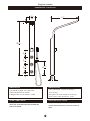
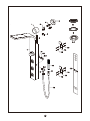
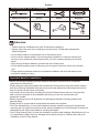
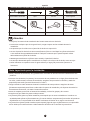
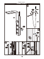
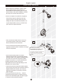
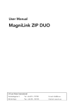
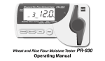
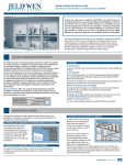
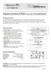
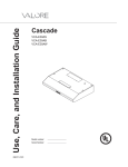
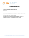
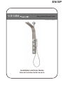
EN/SP
V S 1204
Easy Install Shower Panel
Version No.: V1.20140213
Installation and User Guide
Guía de instalación del usuario
English / Español
DIMENSIONS / DIMENSIONES
15
3 "
16
1
18 "
8
3
4"
3
38 "
8
1
5 8"
1
5 8"
1
5 8"
7
10 "
16
3
24 "
1
2 2"
DIMENSIONS:
DiMENSIONS:
DIMENSIONES:
DiMENSIONS:
• (H) 38.38" x (W) 3.94" x (D) 2.56"
• Hand shower hose: 59.05"
• Weight: Net: 8.7 lbs /Gross: 13 lbs
CODE COMPLIANCE:
• (Alt.) 38.38 pulg. x (Anch.) 3.94 pulg. x
(P) 2.56 pulg.
• Manguera de ducha teléfono: 59.05 pulg.
•CODE
Peso neto:
8.7 lbs; Peso bruto: 13 lbs
COMPLIANCE:
CODE COMPLIANCE:
CUMPLIMIENTO DE CÓDIGO:
This product is tested and certified to
meet U.S. and international standards
cUPC-certified
Este producto fue puesto a prueba y respeta las
normas estadounidenses e internacionales de
cUPC
2
English / Español
FEATURES / CARACTERÍSTICAS
• Panel de una pieza de diseño curvo
• Carcasa hecha enteramente de acero inoxidable
• Revestimiento nanotecnológico que resiste a las huellas
dactilares
• Tres matrices ajustables
• Cabezal de 32 boquillas para una ducha de tipo lluvia
• Mando de selección que permite elegir entre tres
• PVC Handshower with Chrome Plate Finish
• Easy to install bracket system and connection chorros de agua
• Ducha telefono de laton con acabado cromado y
to existing shower head outlet
horquilla
• Sistema de soporte fácil de instalar y conexión al tubo de
salida existente de la ducha
• Single-piece curving panel design
• Full stainless steel casing
• Fingerprint resistant nanotechnology coating
• 3 adjustable spray nozzle arrays
• 32-nozzle overhead "rainfall" shower array
• 3-way shower selector knob
Maximum operating pressure:
125psi
Recommended pressure:
45~80psi
Max. hot water temperature:
176 °F/80°C
Recommended hot water temperature:
120~160°F
Flow rate @ 80 psi:
<2.0gpm
* For safety, it is highly recommended you familiarize yourself with all applicable local plumbing codes and
temperature safety guidelines for your area before setting the temperature on the shower panel (especially for
very hot water settings).
Données techniques
Pression de fonctionnement maximale :
125 lb/po²
Pression recommandée :
45~80 lb/po²
Température maximale de l'eau chaude :
176 °F/80 °C
Débit à 80 lb/po² :
120~160°F
Température recommandée de l'eau chaude :
<2,0gpm
* Pour des raisons de sécurité, nous vous recommandons fortement de vous informer de tous les codes
de plomberie en vigueur et des directives de sécurité en matière de température de votre localité avant
d'ajuster la température du panneau de douche (particulièrement pour les réglages de température
élevés).
3
5
4
2
3
11
6
7
8
9-1
15
1
14
6
13
9-1
9-2
9-3
10
16
11
6
15
13
12
5
14
English / Español
Parts List / Lista de las piezas
ITEM
DESCRIPTION
QTY ARTÍCULO DESCRIPCIÓN
1
Shower Panel Casing
1
2
Shower Head Outlet Connector Cover
1
3
Elbow Connector with Cone Washer
1
4
Brass extender joint (1 5/8"& 2 5/8"x ½") 2
5
Base Plate Cover with Tape
1
2
3
4
1
(for Shower Head Outlet Connector
5
Cover)
6
O Ring Gasket
2
7
Compression Nut in Chrome Finish
1
8
Main PVC Supply Line (43"/110cm)
1
Handshower Cradle Assembly
1
10
PVC Handshower with Chrome Plate
1
11
Filter Gasket
1
12
Handshower Hose
1
13
Screws
4
14
Positioning and Support Brackets
2
15
Anchor Screws
4
16
Installation Template Guide
1
9
6
7
8
9
10
11
12
13
14
15
16
4
CANTIDAD
Carcasa del panel de ducha
Cubierta del conector del tubo de
salida de la ducha
Conector de codo con arandela cónica
Junta de extensión de latón (1.63pulg.
&2,5 pulg. x 0,5 pulg.)
Cubierta de placa base con cinta (para
la cubierta del conector del tubo de
salida de la ducha)
Junta tónica
Tuerca de compresión con acabado
cromado
Conducto principal de alimentación
de PVC (43 pulg./110cm)
Ensamblaje de la horquilla para la
ducha teléfono
Ducha telefono de laton con acabado
cromado
Junta del filtro
Manguera
Tornillos
Placas de soporte y fijación
Tornillos de anclaje
Plantilla de instalación
1
1
1
2
1
2
1
1
1
1
1
1
4
2
4
1
English
Recommended Tools for Installation:
PH +
24mm(15/16")
Phillips Screwdriver
Pencil
Shears
Wrenches
6mm (15/64")
Drill Bit
Level
Hammer
Sealing Tape
Electric Drill
Attention:
• Please read this Installation and User Guide before operating.
• Always take extra care when installing to prevent injury. Please wear appropriate
safety equipment.
• Do not allow children unsupervised use of the shower panel.
• Do not use the shower panel if you are physically impaired or under the influence of
alcohol or any substance which may prevent you from properly operating the shower
panel.
• Keep enough distance between yourself and the shower panel.
• Do not allow sensitive parts of the body such as eyes to come too close to the shower
jets.
• Proper pressure balance needs to be maintained between hot and cold water inputs
to prevent scalding or injury.
Important Note for Installation:
• Before and during installation,please read and familiarize yourself with all installation
instructions for this product.
• Please keep all components,parts and accessories of this product away from small children
and minors.During installation,all screws,tools and small parts should be supervised so that
they do not fall into the hands of children.
• Use caution at all times when installing this product.Please ensure that you are physically
able to perform all parts of the installation and that you have the correct tools and
equipment needed.
• Before beginning,remove all wrappers and packinging materials including staples and
packing straps.
• Please check to ensure that all components and parts are complete.
• The Filter Gasket(Part # 11) must be installed to protect against incoming dirt by pipework.
Incoming dirt can impair the function and/or lead to damages on functional parts of the fixture.
Manufacturer will not be held liable for resulting damages.
• The O Ring Gasket (Part # 6) must be installed to prevent water leakage. Manufacturer will not
be responsible or liable from any damage which results directly or indirectly from failure to
installation of the O Ring Gasket.
6
Español
Herramientas recomendadas para la instalación:
PH +
22mm(0.875 pulg. )
Destornillador de estrella
Alicates
Lápiz
Llaves inglesas
Broca de 6mm
(15/64 pulg.)
Nivel de burbuja
Martillo
Teflón
Taladro eléctrico
Atención:
• Por favor, lea esta Guía de instalación del usuario antes de usar la ducha.
• Para evitar cualquier tipo de riesgo de lesión, tenga siempre mucho cuidado durante la
instalación.
• No permita que los niños usen el panel de la ducha sin supervisión.
• No use el panel de la ducha si tiene una deficiencia física o si está bajo los efectos de alcohol
o Use material de seguridad adecuado.de cualquier sustancia que le pueda impedir utilizar
adecuadamente el panel de la ducha.
• Mantenga una distancia suficiente entre Usted y el panel de la ducha.
• No acerque demasiado partes sensibles de su cuerpo a los chorros de la ducha, como sus ojos.
• Debe mantener un equilibrio entre el agua caliente y el agua fría para evitar quemarse o
lesionarse.
P
Nota
importante para la instalación:
• Antes y durante la instalación, lea y familiarícese con todas las instrucciones de instalación de este
producto.
• Conserve los elementos, las piezas y los accesorios de este producto en un lugar fuera dealcance de
los niños y adolescentes. Durante la instalación, asegúrese de que todos los tornillos y todas las
pequeñas piezas estén fuera del alcance de los niños.l
• Tenga cuidado en todo momento durante la instalación de este producto. Asegúrese de estar
físicamente capacitado para llevar a cabo todos los pasos de instalación y de disponer de todas las
herramientas necesarias y de todo el material necesario.
• Antes de empezar, quite todo el material de embalaje, incluso las grapas y las correas.
• Asegúrese de que todas las piezas están presentes.
• La junta del filtro (pieza 11) debe instalarse para impedir que se meta suciedad en el conducto. La
suciedad puede afectar al funcionamiento y/o causar daños a componentes funcionales del producto.
El fabricante no es responsable de los daños resultantes del hecho de no seguir esta directiva.
• La junta tónica (pieza 6) debe instalarse para impedir fugas de agua. El fabricante no es responsable
de los daños que resulten directa o indirectamente del hecho de no instalar la junta tónica.
7
English / Español
ASSEMBLY / ENSAMBLAJE
a
9-3
7
6
10
11
1
12
9-3
b
9-3
c
d
9-1
9-2
6
9-1
9-3
9-3
8
English / Español
INSTALLATION / INSTALACIÓN
• Before beginning installation, please ensure
there is sufficent space and clearance to
accomodate the shower panel (34"-42" under
shower head). If the space available is outside
this range, the shower panel will not fit.
1
34"~42"
• Antes de empezar la instalación, asegúrese
de que haya espacio suficiente para que
quepa el panel de ducha (34-42 pulg. por
debajo del tubo de salida de la ducha). Si el
espacio disponible es menor, no habrá sitio
para colocar el panel de ducha.
• Turn over the main water valve or source to
your existing shower. Remove the existing
shower head and shower head arm.
• Cierre la válvula principal de suministro de
agua de su ducha. Quite el cabezal y el mango
de ducha empleado.
• Connect the shower panel's 1/2" brass
extender joint (Part # 4) to the existing shower
head pipe outlet. Use waterproof plumbing tape
to secure the connection and prevent leaks.
(*There are 2 sizes of ½“ brass extender joint
(Part#4) provided. Please choose the
appropriate size for this part depending on the
thickness of the shower wall)
2
½" diameter is needed to
accommodate the shower panel's
brassextender joint (Part # 4)
Se necesita un tubo de un diámetro de
0,5 pulg. para instalar la junta de
extensión de latón (pieza 4) del panel
de ducha.
3
4
• Conecte la junta de extensión de latón (pieza
4) de 0,5 pulg. del panel de la ducha al tubo de
salida existente de su ducha. Use cinta de
teflón para proteger la conexión y prevenir
fugas de agua.
(*se proporcionan dos tipos de j unta de
extensión de latón (pieza 4). Elija la junta de
dimensiones adecuadas para esta pieza según
el espesor de la pared de la ducha)
4
9
English
INSTALLATION
Depending on user's height within
the grayed area of the Template
Guide, select the hole number
closest to the location of the
shower head outlet/brass
extender joint (Part 4)
Body Height
4
MIN ½ Inch
Installation Position
3
Recommended range
area for user's height
(measured from top of
the tallest user's head)
4
1
2
• An Installation Template Guide
is included with your shower
panel as a convenient method
of determining the correct
position of the shower panel
and drill in screw anchors/
screws.
Installation Template Guide
STEPS TO USE TEMPLATE:
• Place the template guide on the shower wall over the desired position for the shower panel.
• Have the tallest user at home stand next to the template guide against the shower wall.
• Keeping the top of the tallest user's head level within the Recommended Range Area (marked as
darkened section at 25 1/4" and 31 1/3" height on template), find the desired height level relative
to the position of the 5 holes on top of the template).
• Determine which of the five holes above the template is closest to the outlet of the existing
shower \ head with brass extender joint attached in Installation Part 3.
• Mark which hole is closest to the correct desired position and place the template against the
shower wall with shower head outlet/brass extender joint inside the hole marked.
• One the template position is selected and the shower head outlet is inside the selected hole,
double check to make sure the tallest persons' top-of-head level is still within the gray marked
area printed on the template.
10
Español
INSTALACIÓN
3
Estatura
Espacio libre recomendado
por encima del usuario (medido
desde la parte superior de la
cabeza del usuario más alto)
Posición de instalación
Según la estatura del usuario, elija el
número de agujero más cercano a la
posición del cabezal de la ducha o de
la junta de extensión de latón (pieza
4) en la zona gris de la plantilla de
instalación.
4
4
MIN ½ Inch
1
2
• Se incluye una plantilla de
instalación con el panel de ducha
para determinar la posición correcta
del panel de ducha y de los tornillos
y tornillos de anclaje.
Plantilla de instalación
PASOS PARA USAR LA PLANTILLA:
• Coloque la plantilla contra la pared de la ducha, en el emplazamiento donde quiera instalar el panel de la ducha.
• Pida al usuario más alto que se quede de pie al lado de la plantilla, contra la pared de la ducha.
• Guardando la parte más alta del usuario al nivel del Espacio libre recomendado (indicado en la sección oscura
de la plantilla, entre las alturas de 25,25 pulg. y 31,3 pulg.), determine la altura deseada mediante los cinco
agujeros que aparecen en la plantilla.
• Determine cuál de los cinco agujeros de plantilla corresponde al tubo de salida de agua de la ducha existente
o de la junta de extensión de latón instalada en el paso 3 de las instrucciones de instalación.
• Marque el agujero que está más cerca de la posición deseada y coloque la plantilla contra la pared de la ducha,
introduciendo el tubo de salida de agua o la junta de extensión de latón en el agujero elegido.
• Una vez que haya determinado la posición de la plantilla y haya introducido el tubo de salida de agua en el
agujero deseado, asegúrese de que la parte superior de la cabeza del usuario más alto quede dentro de la
sección gris de la plantilla.
11
English
INSTALLATION
Draw a level horizontal line based on
the lower-edge of the selected hole
5
This section will help you measure the
required length of the Main PVC Supply Line
(Part 8) relative to the final position of the
Template Guide
8
Steps:
• Measure the distance between the bottom of
the template to the closest approximate hole
position on the top of the template which
corresponds to where the shower outlet pipe
is. Refer to this distance as "d1".
d1
d1
Shear
• Add 1 inch to your "d1" measurement.
• Using the length of "d1" as a guide, measure
this length on the Main PVC Supply Line Hose
(Part 8) and shear the excess length from the
hose.
Connecting the elbow connector assembly to
the main PVC supply line:
6
3
• Insert top-end of Main PVC Supply Line (Part 8)
into the Chrome Compression Nut (Part 7).
3
7
• Insert Part 3 into combination of 7/8 and
tighten in a clockwise turn motion while gently
but firmly pushing downwards until the main
PVC supply line is properly connected to the
elbow connector valve with o-ring gasket and
chrome compression nut is in between.
8
7
8
12
Español
INSTALACIÓN
Dibuje una línea horizontal nivelada basándose en
la parte inferior del agujero seleccionado
5
Esta sección le ayuda a medir la longitud
necesaria del conducto principal de
alimentación de PVC (pieza 8) respecto a la
posición final de la plantilla.
8
Pasos:
• Mida la distancia entre la parte inferior de la plantilla
y la posición del agujero más cercano a la plantilla que
corresponda al lugar donde se encuentra el tubo de
salida de la ducha. Esa distancia corresponde al “d1”.
d1
d1
Alicates
• Añada 1 pulgada a la medida “d1”.
• Utilizando como guía la medida “d1”, mida esta
longitud en el conducto principal de alimentación de
PVC (pieza 8) y corte la parte del conducto que sobre.
6
Conexión del conector del ensamblaje de codo con el
conducto principal de alimentación de PVC :
3
3
• Inserte el extremo superior del conducto principal
de alimentación de PVC (pieza 8) en la tuerca de
compresión cromada (pieza 7).
7
8
7
• Inserte la pieza 3 en la combinación de las piezas 7 y
8 y fíjela girando en el sentido a las agujas del reloj,
empujando firme y suavemente hacia abajo hasta
que el conducto principal de alimentación de PVC
esté adecuadamente conectado a la válvula del
conector de codo, insertando entre las dos piezas la
junta de goma y la tuerca de compresión cromada.
8
13
English
INSTALLATION
• To ensure the template (and your shower panel)
will be in a completely straight and level position,
use a level tool against the side of the template
guide to make fine adjustments to the template
guide's position until fully level.
7
• Once fully level, this will be the final position of
the template guide.
• Take a pencil/marker and mark the positions of
the anchor screws (Part 15) for which 4 holes
will need to be drilled.
• Use the drill with correct indicated sized drill
bit to drill each of the 4 holes as marked in
step 6. Do not drill too deep a hole - only
enough depth to fully enclose the anchor
screws. Note: Please double check to ensure
there is no existing water pipes or obstruction
behind area you are drilling. If there is an
obstruction, you will need to reposition the
template guide to avoid it.
8
9
• After holes have been drilled, insert the
provided Anchor Screws (Part 15).
15 x4PCS
14
Español
INSTALACIÓN
•Para asegurarse que la plantilla (y el panel de la
ducha) estén rectos y nivelados, use un nivel de
burbuja en el lado de la plantilla para ajustar la
posición de la plantilla hasta que esté totalmente
nivelada.
7
•Cuando esté nivelada, se tiene la posición final de
la plantilla.
•Con un lápiz o rotulador, marque las posiciones de
los tornillos de anclaje (pieza 15), donde tendrá que
taladrar cuatro agujeros.
•Use el taladro con una broca del tamaño indicado
para hacer cada uno de los cuatro agujeros marcados
en el paso 6. No haga un agujero demasiado profundo
, sino a la profundidad necesaria para instalar los
tornillos de anclaje. Nota: Asegúrese de que no haya
tubos de agua u otros elementos detrás de los sitios
donde va a taladrar. Si se encuentran elementos,
tendrá que cambiar el emplazamiento de la plantilla
para evitarlos.
•Una vez hechos los agujeros, inserte los tornillos de
anclaje (pieza 15) proporcionados.
8
Diámetro del
agujero = 6,5
Profundidad = 30
9
15 x4PCS
15
English
INSTALLATION
• After anchor screws have been installed, affix
the Positioning & Support Brackets (Part 14)
using supplied Screws (Part 13).
10
14 x2PCS
PH +
13 x4PCS
11
For the Positioning & Mounting Brackets
(Part 14), please make sure that they are
installed with protruding portion facing
upward as shown in the drawing.
14
16
Español
INSTALACIÓN
•Una vez instalados los tornillos de anclaje, fije las
placas de soporte y fijación (pieza 14) con los
tornillos (pieza 13) proporcionados.
10
14 x2PCS
PH +
13 x4PCS
Asegúrese de que las placas de soporte y fijación
(pieza 14) estén instaladas con la parte saliente
hacia arriba, como se enseña en la ilustración.
11
14
17
English
INSTALLATION
• After all connections have been completed on
the rear of the shower panel, it is ready to be
hung unto the shower wall for permanent
installation.
12
• Simply raise the shower panel and bring close
to the surface of the shower wall and gently
lower it until the bracket support struts
pre-welded at the back of the shower panel
meet the Positioning & Support Brackets
installed in step 10. Please ensure the middle
part of the brackets (Part 14) are centered to
the middle part of the bracket support struts
which have a cut-out section to lock in the
brackets.
14
• Once a snug and secure fit is achieved and all
parts of the PVC Supply Line are secured to the
back of the shower panel, silicone sealant can
be applied to the rear of the shower panel
casing to hold it in place and prevent water
from entering the rear of the panel.
a. Peel off the adhesive paper from the back of
the Base Plate Cover (Part 5)
b. Position the flat side of Part 5 with adhesive
facing the shower wall and apply pressure to
secure it.
14
13
a.
b.
5
4
Note: Please make sure this surface is free
from dirt and residue to ensure the adhesive
bonds with the wall. If the existing shower
pipe outlet does not protrude from the wall,
then there is no need to apply the Base Plate
Cover (Part 5) and the Shower Head Outlet
Connection Cover (Part 2)
c.
c. Join the Elbow Connector/Main PVC Pipe
assembly to the Brass Extender Joint (Part 4) by
connecting them and turning clockwise to tighten
(do not over-tighten).
d. Install the Shower Head Connector Cover
(Part 2).
d.
4
3
2
Congratulations! You have completed
installation of your new Valore shower panel!
We hope you enjoy using your new shower
panel for many years to come! If you have
questions, comments or need assistance,
please contact us using the information on
the next page. Thank you!
8
8
18
5
Español
INSTALACIÓN
• Una vez hechas todas las conexiones en la parte
trasera del panel, se puede colgar el panel de la
pared de la ducha para una instalación permanente.
12
• Levante simplemente el panel de la ducha y
acérquelo a la superficie de la pared de la ducha.
Bájelo delicadamente hasta que los ganchos de
soporte pre-soldados de la parte trasera del panel
de ducha se introduzcan en las placas de soporte y
fijación instaladas en el paso 10. Asegúrese de que la
parte central de las placas de soporte y fijación
(pieza 14) estén centradas en la parte central de los
ganchos de soporte, los cuales tienen secciones
cortadas donde se deben enganchar los soportes.
14
•Una vez conseguido un ajuste sólido y que todas las
piezas del conducto principal de alimentación de
PVC estén fijadas a la parte trasera del panel de
ducha, aplique silicona a la parte trasera de la carcasa
del panel de ducha para fijarla en el sitio y prevenir
que se introduzca agua detrás del panel de la ducha.
a. Quite el papel adhesivo de la parte trasera de la
cubierta de la placa base (pieza 5).
b. Coloque la cara plana de la pieza 5 en la pared de
la ducha con adhesivo y aplique presión para fijarla
en su lugar.
14
13
a.
b.
5
4
Nota: Asegúrese de que no haya suciedad ni residuos
en esta superficie para que el adhesivo pegue a la
pared. Si el tubo de salida existente no sale de la
pared, no hace falta instalar la cubierta de placa
base (pieza 5) ni lacubierta del conector del tubo de
salida de la ducha (pieza 2).
c.
c. Conecte el ensamblaje del conector de codo y del
conducto principal a la junta de extensión de latón
(pieza 4) girando en el sentido a las agujas del reloj
(no apriete demasiado).
d. Instale la cubierta del conector del tubo de salida
de la ducha (pieza 2).
d.
4
3
2
¡Enhorabuena! ¡Terminó la instalación de su
nuevo panel de ducha Valore! ¡Esperamos que
disfrute de su nuevo panel de ducha durante
muchos años! Si tiene preguntas, comentarios
o si necesita ayuda, póngase en contacto con
nosotros utilizando la información de la
página siguiente. ¡Gracias!
8
8
19
5
Have Questions?Need Assistance?
Leave Feedback?
VALOREUSA
[email protected]
Hours:
Monday thru Friday
8:30AM-5:30PM(PST)
¿Alguna pregunta? ¿Necesita ayuda?
¿Comentarios?
VALOREUSA
[email protected]
Horas de trabajo:
Lunes a viernes
8:30 AM - 5:30 PM (PST)