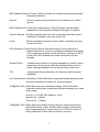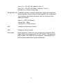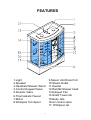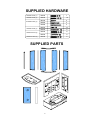
1
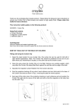
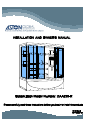
Before you start
Thank you for purchasing your Aston steam shower with attached whirlpool bath.
We hope that it will provide you with years of satisfying use and enjoyment. This
instruction manual explains the benefits of using a steam shower and provides
installation, operation, and care instructions for your new Aston steam shower with
attached whirlpool bath.
Please read this manual carefully because it contains information and instructions
about the safe installation and operation of the unit. If you do not follow certain
conditions of installation and maintenance, your warranty may be affected.
Whether your unit is a standalone steam shower or contains an attached whirlpool
bath, we have designed the unit to provide you with a safe and relaxing
environment to refresh your mind and body. Since ancient times, the act of taking
a steam sauna has proven beneficial to promoting and living a healthy lifestyle.
Exposing your skin to the warm moist heat of a steam sauna will open your pores
helping you to expel dirt and toxins from your body while leaving your skin clean
and healthy. In addition, regular use of a steam sauna can be a relaxing time that
transports you from the hustle and bustle of daily life for a few moments.
Some units are equipped with a built in whirlpool bath providing the additional
experience of hydrotherapy giving you a relaxing massage and alleviating sore
muscles and joints.
Aston steam showers come equipped with many enhanced features as standard
equipment, thus eliminating the need to make costly upgrades.
Aston steam shower features include:
Thermostatic valve
Overhead rain shower head
Handheld shower wand
FM tuner with speaker
Aux/CD input for optional MP3 player or CD player
Built - in light
Built - in exhaust fan
Mirror
Built - in steam generator
Ample storage for your body care products
Durable fiberglass reinforced acrylic
Tempered glass
Solid state controls
1
Important Safety Instruction
WARNING: To reduce the risk of drowning, electrical shock, or injury, read the
following important precautions before using the unit. If you do not fully
understand the meaning of any of the precautions and warnings please consult
your dealer or the manufacturer for a full explanation. Do not use the unit until
you understand all of the following:
1.WARNING: Read and follow all instructions.
2. DANGER: To reduce the risk of injury, do not permit children to use the unit
unless they are closely supervised.
3. WARNING: Use this unit only for the intended purpose described in this
manual; do not use attachments not recommended by the manufacturer.
4. WARNING: Never drop or insert any objects into any opening.
5.WARNING: The unit must be connected to a supply circuit that is protected
by a ground fault circuit interrupter (GFCI). This GFCI should be provided by
the installer and routinely tested.
To test the GFCI:
a. Push the “test” button. The GFCI should interrupt the power going to
the unit.
b. Press the “reset” button and power should be restored.
If the GFCI fails to operate as described, the GFCI is defective and must be
replaced. If the GFCI interrupts power to the unit without the test button being
pushed, a ground fault has occurred. Discontinue use and contact your dealer
or service provider.
6.WARNING: If you have a pre-existing health condition such as obesity,
heart disease, high or low blood pressure, circulatory problems, or diabetes,
consult your physician before use. If you are pregnant or could be pregnant, do
not use the unit without consulting your doctor.
7.WARNING: Observe reasonable time limits when using this product. Long
exposures at high temperatures can cause high body temperatures.
Symptoms may include dizziness, nausea, fainting, drowsiness, and reduced
awareness. These effects could possibly lead to drowning.
8.WARNING: The water jets produce a stream of water with relatively high
pressure. Prolonged exposure of high-pressure water to a localized area of the
body may cause bruising.
9. WARNING: Prolonged immersion in hot water or steam may induce
hyperthermia. A description of the cause, symptoms and effects of
hyperthermia are as follows:
a. Lack of awareness of impending hazard;
b. Failure to perceive heat;
c. Failure to recognize the need to exit the unit;
d. Fetal damage in pregnant women;
e. Unconsciousness and danger of drowning.
2
THE FOLLOWING WARNING ONLY APPLY TO UNITS THAT ARE A
COMBINATION STEAM SHOWERS/STEAM BATH UNIT CONTAINING AN
ATTACHED HYDRO-MASSAGE BATHTUB
1.WARNING: To avoid the risk of accidental injury or drowning children
should not use the hydro massage bathtub without adult supervision.
2.WARNING: To avoid injury, take care when entering or exiting the
hydro-massage bathtub.
3.WARNING: To avoid unconsciousness and possible drowning, do not take
drugs or drink alcohol before or during the use of a hydro massage bathtub
equipped with a heater.
4.WARNING: To prevent risk of fetal injury, a pregnant or possibly pregnant
woman should consult a doctor before using a hydro massage bathtub
equipped with a heater.
5.WARNING: To reduce the risk of hyperthermia and possible drowning, do not
use a hydro massage bathtub equipped with a heater immediately following
strenuous exercise.
6.WARNING: To reduce the risk of electric shock, do not permit electric
appliances (such as a hair dryer, lamp, telephone, radio, or television) within
1.5m (5 ft.) of a hydro massage bathtub.
7.CAUTION: Test the ground fault circuit interrupter (GFCI) protecting this
appliance periodically in accordance with the manufacturer's instructions.
8.WARNING: Water temperature in excess of 40 C (104 F) may be injurious to
your health and increase the risk of hyperthermia and drowning.
9.WARNING: To reduce the risk of hyperthermia, people using medication and
or having an adverse medical history should consult a doctor before using a
hydro massage bathtub equipped with a heater.
3
Terms and Definitions
Becoming familiar with commonly used plumbing and electrical terms will help you
as you use this owner's manual and when you consult the dealer regarding parts
and service.
Amperes
Commonly called Amps, rating for flow of electricity
AWG
American Wire Gauge (see Wire Gauge), sizing standard for wire
diameter
Circuit
Closed loop of electricity
Circuit Breaker Mechanical device to switch power to a circuit on and off
Circuit Load
Maximum number of amps a circuit can carry defined by the
total load (Amps) of all components within a circuit. Circuit load
determines the size of the circuit breaker used to protect it
CSA
The Canadian Standards Association develops products safety
standards for Canada similar to UL in the USA
GFCI (Ground Fault Circuit Interrupter) (USA) Breaker that interrupts the flow of
electricity when it detects voltage going to ground. This type of
breaker is required to connect any whirlpool bath, steam shower,
or hot tub to household power
Ground
Creates the path of the least resistance for electricity and servers
as a backup for the neutral wire
GPM (Gallons per Minute) (USA) Measure of flow rate
Heater
Electrical resistance device containing the heating element
Hz (Hertz)
The unit of measure of impedance, equaling the number of
cycles per seconds of electrical flow. USA and Canada power is
supplied at 60Hz. International power is supplied in 50Hz
Jet
kW (Kilowatt)
Device that ejects water at an elevated pressure
Measure of electrical power (example 1000W = 1kW) defined by
the following equation: Watt = Volt x Amp
kWhr (Kilowatt Hour) Measures rate of power usage over one hour. Power
companies charge a certain rate per kWhr (example $0.15/kWhr)
4
NEC (National Electric Code) (USA) Universal set of standards governing proper
electrical installation
Neutral
When measure using a multi-meter will measure 0 to earth
ground
NFPA (National Fire Protection Association) (USA) Develops national safety
standards for fire protection related to all types of material
Owner's Manual
Booklet supplied with each unit containing information about
installation, operation, and care of the unit
Pump
Electro-mechanical device to move water, consisting of a wet
end and a motor
RCD (Residual Circuit Device) Device that disconnects a circuit wherever it
detects that flow of current is not balanced between the phase
(“hot”) conductor and the neutral conductor. Similar to a GFCI
in the USA. RCD breakers are used outside the US and
Canada
Suction Fitting
Located at the bottom of a hydro massage tub, used to return
water back into the pump. Must be installed before use of a
hydro massage bathtub and correctly working at all times
TUV
Independent testing laboratory for Germany and European
standards
UL (Underwriters Laboratory) (USA) Nationally recognized testing laboratory that
develops standards for safety for various products
120@60Hz VAC (USA) Most common residential voltage. VAC delivered to
customers using three conductors with the following color code
and voltage:
Line (L) = 110-120 VAC (Black or “Hot”)
Neutral (N) = (White)
Ground (G) = (Green)
220@60Hz VAC (USA) Required voltage for large ampere equipment such as
residential electric ovens, electric water heaters, and hottubs.
Some large appliances require the use 110VAC for control or
other peripheries in this case a neutral is required
5
Line (L1) = 110-120 VAC (Black or “Hot 1”)
Line (L2) = 110-120 VAC (Red or White or “Hot 2”)
Ground (G) = (Green or Bare wire)
230 @50Hz VAC (International) Most common residential voltage in Europe and
other countries outside of the US and Canada. VAC is delivered
to customers using three conductors with the following color
code and voltage:
Line (L) = 230 VAC (Brown)
Neutral (N) = (Blue)
Ground (G) = (Yellow/Green)
VAC
Voltage for Alternating Current
VDC
Voltage for Direct Current
Wire Gage
Actual diameter of bare wire only, measured in American Wire
Gage (AWG) units ranging from 30 to 00 (AWG). The larger the
gage number, the smaller the wire diameter. International wire
size units are measured in square millimeters
6
FEATURES
1.Light
2.Speaker
3.Handheld Shower Wand
4.Control Keypad Panel
5.Diverter Valve
6.Thermostatic Faucet
7.Mirror
8.Whirlpool Tub Spout
7
9.Steam Unit Drain Port
10.Steam Outlet
11.Handle
12.Rainfall Shower head
13.Exhaust Fan
14.Shelf/ Towel rail
15.Body Jets
16.Air control valve
17. Whirlpool Jet
SUPPLIED HARDWARE
SCREW PACK (1)
M5x30
7
SCREW PACK (2)
M5x35
10
M4x30
4
M4x50
M4x60
4
4
M4x16
M5x40
14
5
M4x30
8
M4x35
6
M4x30
2
SCREW PACK (3)
SCREW PACK (4)
SCREW PACK (5)
SCREW PACK (6)
SUPPLIED PARTS
8
Installation Guide
Please read and follow the installation instructions and guidelines in this section.
Failure to follow the recommended instructions and installation techniques may
lead to possible damage to the unit or the surrounding area and can affect
warranty claims.
ATTENTION: This unit requires assembly. We strongly encourage you to use a
minimum of two people to aid in the assembly, as several of the sections are large
and unstable until assembled.
You will need to consider several factors when planning for your installation
location. While all installations are unique, the following are general guidelines:
1.WARNING: The unit requires electrical power to operate and is required by
code to be connected to a GFCI protected circuit by a licensed electrician.
NEVER connect this unit to a circuit that is not GFCI protected.
2.The unit is designed for indoor use ONLY.
3.Unit requires a licensed plumber for installation.
4.The installation must allow for future service. The unit is designed to be
modular meaning the unit can be moved as a whole piece after assembly with
flexible supply lines and a flexible drain. All electronic components and
plumbing connections are typically located on the back wall of the unit, which
in many cases is next to a service wall. In the event that service is required,
the repair technician will require access to these components.
2.If you are planning for a permanent installation, you must provide access to
the back of the unit through some type of service panel. NOTE: Aston Global,
Inc. is not responsible for and will not reimburse the cost to fix any
damage or any repairs needed that are caused by the need to service the
unit even if the service work required is under warranty.
6.CAUTION: A flexible drain kit is provided with the unit. The distance between
the floor drain and the unit drain should not exceed 18 inches centerline to
centerline.
9
7. CAUTION: The flexible drain should have a level or slight grade to allow free
and easy flow to the floor drain. Failure to do so can cause possible leaks
and flooding.
8. WARNING: It is recommended that the exhaust fan provided with the unit be
vented to the outside to provide proper steam ventilation after use. See page
20 for more information.
9. In order to avoid any unwanted movement, the unit should be installed on a
properly supported flat and level non-slip surface.
Before starting the installation, please ensure that you have inspected all
components of the unit and check for broken or damaged sections. If you find
damage, please contact your dealer or the manufacturer.
These installation instructions assume you have already completed the following
works:
Rough plumbing for both the hot and cold supply lines
Placing of the floor drain
Rough electrical for the unit
You will need the following tools:
Drill with screwdriver attachments
Caulk gun
Level (3 foot or longer is recommended)
Tape measure
Box and open end wrenches or socket set (metric)
Phillips head screw driver
Flat head screw driver
Bathroom rated silicone sealant
Adjustable wrench
Plumbing Requirements:
Installation by a Licensed plumber
Water pressure: 60 - 80 psi
Flow rate: 6-10 GPM (gallons per minute)
For hose connection male 3/8: compression fitting threads
10
Electrical Requirements
Unit must be connected by a licensed electrician for your state to a GFCI
protected circuit in order for the warranty to be valid.
Installation by a Licensed Electrician
30Amp service at 120 VAC @ 60 Hz
GFCI breaker required
11
Installation
Install your unit according to the directions in this section in the order presented.
Locate the accessory and manual box and remove the individual screw and
hardware packages and lay them out in sequential order to aid in completing the
rest of the installation.
Step 1 Level the whirlpool bath for proper drainage
The whirlpool bath is constructed with several leveling feet. Each foot has a
locking nut. Use an adjustable wrench and level to complete this next step.
1.Loosen all of the locking nuts so that the leveling feet are free and easy to
move.
2. Place the whirlpool bath into the exact final installation location or a flat
surface.
3.Place the level across the top of the whirlpool bath (side to side) and level
the whirlpool bath by adjusting the leveling feet.
NOTE: You may need to remove the whirlpool bath in order to adjust the leveling
feet, but always recheck the level with the unit in the final installation location.
4. Place the level across the top of the base (front to back) and level the base
by adjusting the leveling feet.
12
WARNING: Failure to apply proper pitch or grade for drainage can cause leaking
and/or flooding of the area surrounding the unit.
1.After making all the leveling adjustments ensure that all leveling feet
(including center foot) are in contact with the floor. To ensure the unit is
supported, stand in the whirlpool bath in several places looking for any
movement and adjust as needed.
2.After ensuring all leveling feet are in contact with the floor, tighten the locking
nut on each leveling foot ensuring that all leveling feet are secure.
3.Once all the leveling feet are secure, place the whirlpool bath back into the
final installation location and verify all the leveling adjustments remain as
before. Adjust as needed.
13
Step 2 Optional drain connections
The Whirlpool tub comes equipped with a factory installed drain and overflow an
optional flexible drain hose is also provided to avoid having to move the floor
drain.
Please see the Drain diagram for the optional drain hose.
Flex drain hose
Use the following instructions for the standard straight drain:
1.Move the floor drain so that the floor drain and whirlpool tub drain are in line
when the whirlpool tub is in it's final position
2. With the whirlpool tub in it's final location make the plumbing connections
between the whirlpool tub and the floor drain.
Use these instructions for installation of the optional floor drain:
1. Apply sealant to the drain hose gasket and into the compression nut.
2. Install the hose, compression nut, and gasket assembly onto the lower drain
body.
3.Tighten the compression nut so that the gasket is compressed creating a
positive seal.
14
Step 3 Assemble the glass panel
SCREW PACK
(3)
1.Remove and inspect all of the glass panels. If any are broken, please
contact your dealer or the manufacturer.
NOTE: The glass panels are labeled to indicate the direction for the top of the
glass panels.
2. Remove and inspect the aluminum top and bottom rails for the glass
assembly.
NOTE: The aluminum rails are labeled to distinguish the top and bottom rail and
their orientation within the assembly.
IMPORTANT: Please take note that Screw Pack 3 contains several different
lengths of screws each for a specific location within the glass assembly.
During the next steps of assembly, pay close attention so the correct screw
length is used in the correct location. Failure to do this can cause damage to
the glass panels and possibly result in leaks.
15
3. Place the bottom aluminum rail on the floor with correct orientation up to
receive the glass panel.
4. Apply a liberal bead of sealant on the bottom rail from the slot that receives
the glass panel out to the end of the rail.
NOTE: The next steps of assembly will require two people.
5. Choose the left side glass panel and insert it into the left slot on the bottom
rail.
6. While holding the left panel insert the right panel into the right side slot.
7. Take the top aluminum rail and apply a liberal bead of sealant from the slot
for the glass panel out to the end of the rail.
8. Line up the slot on the top rail with the receiving tabs on the glass panels and
insert the top rail on to the glass panels.
9. Using the screws and washers from Screw Pack 3 follow the diagram to
insert the correct screw length in to the correct location.
10. Start with the corners of the glass panel assembly then proceed to insert the
screws into the top and bottom of the assembly.
11. After all the screws are in place and secure, wipe any excessive sealant and
use the excess to fill any cracks or gaps between the joints.
For this unit an additional aluminum channel is provided for the assembly of the
side glass to the glass door panel.
16
Use the following steps to assemble the glass side panel on to the glass door
panel
Insert the aluminum channel on to the glass door panel based on the hand of the
unit.
NOTE: No silicone is needed at this time after final assembly of the unit you will
come back and apply silicone to this join
Insert the glass side panel into the aluminum channel on the glass door panel.
Again no silicone is needed during this step.
The Glass assembly is now complete proceed to the next step.
17
Step 4 Assemble the acrylic back and side panel(s)
SCREW PACK
(1)
1.Open and remove the acrylic back and side panel(s) and inspect for
damage.
IMPORTANT: Please note the direction of the screw head. Make sure you can get
a screwdriver or drill bit on each screw head. Depending on your unit, you may
need to use screwdrivers or drill bits of various sizes to gain proper access to each
screw head.
2. Working on a flat surface loosely bolt the back and side panel(s) together
making sure the tops of the panels are aligned. Use the M5 X 30mm screws
and washers located inside Screw Pack 1. Be sure to leave enough space
between the panels so that you can get the tip of a caulk gun in between the
panels.
NOTE: All panels are pre-drilled and should line up. If you find that some of the
holes do not align investigate the cause and try to determine the issue. If no issue
can be found for the misalignment you can, if needed, enlarge a hole, move or add
additional holes. Be sure to pilot drill the new hole location first before moving to a
larger bit. Failure to use a pilot drill can cause the acrylic to crack or chip. Fill any
unused hole with sealant.
18
3. Using a caulk gun with appropriate bathroom caulk place the tip of the caulk
gun into the opening between the two panels. Run a bead of caulk down one
side of the panel passing over each screw and bolt hole. Apply a generous
amount of caulk.
4. Ensuring that the bottom and top of the panels are still aligned HAND tighten
only the M5 X 30mm screws starting with the bottom and working your way
to the top adjusting the panels as needed to keep them aligned.
5. Leave the acrylic panel assembly hand tight until the unit is fully assembled.
This will aid in alignment for the next steps.
NOTE: If your unit has a second acrylic side panel repeat steps 1-5 to complete
the assembly.
19
Step 5 Install the acrylic wall assembly
on the whirlpool bath
SCREW PACK
(2)
NOTE: The acrylic wall assembly can be heavy so please use caution when lifting
it and placing it onto the whirlpool bath.
1.Lift and place the acrylic wall assembly onto the whirlpool bath to dry fit and
check for proper hole alignment.
NOTE: The whirlpool bath should align to the acrylic wall assembly. If you find it
does not, then investigate the cause and try to determine the issue. If no issue can
be found for the misalignment, you can enlarge the holes or add additional holes.
If you choose to add a hole, make sure to pilot drill first so you so do not crack or
chip the acrylic. Use a pilot drill size that is smaller than the minor diameter of the
screw to be used. If you adding additional mounting holes then you will need to
get the necessary hardware as it is not provided.
2. After checking the hole alignment, remove the acrylic wall assembly from
the whirlpool bath.
20
3. Apply a liberal bead of sealant onto the whirlpool bath in line with the
mounting screw holes.
4. Place the acrylic wall back onto the whirlpool bath and align the mounting
holes.
5. Use the M5 X 35mm screws and washers from the Screw Pack 2 insert and
start all screws in their respective holes, but do not fully tighten.
6. Leave the screws hand tight only until the unit is fully assembled. This will aid
in the alignment for the next step in assembly.
21
Step 6 Install the glass panel assembly
on to the whirlpool bath
SCREW PACK
(4)
NOTE: As with the acrylic assembly, the glass panel assembly is heavy to lift.
Please use caution when lifting this assembly and use two people to lift it into
place.
1.Lift and place the glass panel assembly onto the whirlpool bath and acrylic
panel assembly.
2. Once in place verify the alignment of all holes between the acrylic walls and
the glass assembly.
NOTE: The acrylic walls should align with the aluminum frame of the glass panel
assembly. If you find they do not investigate the cause and try to determine the
issue. If no issues can be found then you can add or enlarge holes as needed in
the acrylic. We do not recommend adding holes into the aluminum frame;
however, if you choose to add additional holes to the aluminum frame choose a
drill size that is smaller than the minor diameter of the screws provided.
3.After verifying the hole alignment, remove the glass panel assembly.
4. Apply a liberal bead of sealant down each side of the acrylic walls in line
with where the glass panel assembly will be in contact with the mounting holes.
22
5. Apply an additional bead of sealant along the whirlpool bath where the glass
panel assembly will sit.
6. Place the glass panel assembly back onto the whirlpool bath assembly
aligning the holes.
7. Using Screw Pack 4 lightly screw the acrylic panels into the aluminum frame
of the glass panel assembly.
8. Leave the screws hand tight only until the unit is fully assembled to aid in the
alignment for the next step in assembly.
9. You will find a separate Screw Pack 4 with a single screw and decorative
cap. Insert this screw into the center hole located on the bottom aluminum rail.
Once installed, place the decorative cap into the exposed center hole.
23
Step 7 Install the ceiling panel
SCREW PACK
(5)
NOTE: The ceiling panel is large and can be an odd shape. Please use caution
when lifting this assembly and use two people to lift it into place.
1.Lift the ceiling into place onto the glass and acrylic walls.
2. Once in place verify that all of the holes align.
NOTE: All of the holes should be aligned. If you find any that are not investigate
the cause. If no cause can be determined then you can choose to enlarge or add
additional holes. Always remember to pilot drill any new holes before enlarging.
3. Remove the ceiling and apply a generous bead of caulk around the top of the
unit in line with the mounting holes.
4. Using Screw Pack 5 use the M4 X 35mm screws and washers to lightly
screw down the front of the ceiling into the aluminum frame of the glass panel
assembly.
5. Using the M4 X 30mm screws, bolts, nuts, and washers, lightly bolt the ceiling
to the acrylic wall panels.
6. Leave the screws and bolts only hand tight to aid the alignment of the final
assembly.
24
Step 8 Final assembly and sealing
After you have installed and lightly assembled the cabinet walls, you can begin to
fully secure all screws and bolts.
Tighten the screws in the following order:
1.Acrylic wall to acrylic wall joint
a.
Starting with the acrylic wall joint ensure that the bottom and top of
the panels are still aligned and tighten the M5 X 30mm screws starting with
the bottom screw and working your way to the top adjusting the panels as
needed to keep them aligned.
b.After tightening all of the screws wipe away excess sealant allowing
the excess to fill any cracks or gaps paying special attention to the screw
and bolt holes.
c.Inspect the inside corner of the two panels checking for a tight even joint
and adjust if needed.
d.
After final inspection, apply a little sealant to each nut to help ensure
the nut stays tight and wipe away any excess.
2.
Acrylic wall to glass panel joint one side then the other
e.
Starting from the bottom of the joint tighten all the screws working
your way from the bottom to the top.
f. After completing one side move to the other acrylic wall to glass panel joint.
g.
After securing both joints inspect the interior joint and wipe away any
excess sealant filling in any cracks or gaps in the joints.
3.Acrylic wall to the whirlpool bath
h.Attach the acrylic walls to the whirlpool bath, screw down all of the
screws starting at one side and working your way to the other side.
i. Inspect the interior joint between the acrylic wall and the whirlpool bath to
ensure that sealant fills the entire length of the joint and add more if
needed.
4.
Ceiling to acrylic wall and glass panel assembly
j. Starting with the M4 X 35mm screws located at the front of the ceiling
screw down the ceiling fully into the top rail of the aluminum frame.
k.Using the M4 x 30mm bolts fully secure the ceiling down to the acrylic
panel assembly.
When you have finished the final tightening of all screws and bolts conduct a final
inspection of the interior joints and seals and wipe away any excess sealant now
as once it becomes set it will be more difficult to remove.
25
Step 9 Install the decorative trim panels
(depending on the unit)
SCREW PACK
(6)
If your unit includes a decorative trim panel, use the following steps to install the
trim piece.
1.Using Screw Pack 6 use the M4 X 30mm screws, nuts, and washers to bolt
the trim piece into the ceiling panel
2. Using the M5 X 25mm screws, screw the trim piece into the whirlpool bath
unit
26
Step 10 Install glass sliding doors
1.Remove and inspect the glass doors. If any are damaged or broken, please
contact your dealer or the manufacturer.
2. Determine which door is the right door and which is the left by locating the
two holes used for the door handles. When the doors are closed, the handles
will be next to each other in the center of the door opening.
Eight roller mount assemblies for the doors are located inside the unit on the
upper and lower aluminum rails.
3.Carefully disassemble each door roller mount assembly.
IMPORTANT: Note the disassembly order of the roller mount assembly. It is
critical that the order be repeated for proper adjustments of the doors. Please see
the illustration provided.
4. Remove the decorative nut, locking nut, and plastic washer. Leave the
plastic
27
tube and back plastic washer on the door roller.
5. Taking one of the doors, with the two holes for the door handles located so
that they are in the center of the door opening, slide the door over the top
two-door roller mounts. IMPORTANT: The plastic tubes must be inserted into
the two top mounting holes in the door.
6. Reinstall the plastic washers onto the top roller and then install the metal
locking nuts. Hand tighten the locking nuts.
7. Repeat the process on the two lower roller mounts ensuring that the plastic
tubes are inserted in the glass door and then reinstall the plastic washer and
metal locking nut and hand tighten.
8. Repeat the process on the other door. Only hand tighten the metal locking
nuts.
9. After both doors are installed, close both doors.
10. Check the door seal down the length of the seal. If it is not in full contact, use
a flat head screw driver and adjust the top roller mounts so that the door seal
is in contact for the entire length of the door.
NOTE: A cam roller inside of the door roller is used for adjustments of the door. By
turning this cam, you will raise or lower the door by adjusting the seal.
11. After making the final adjustments, tighten all of the metal locking nuts.
12. Install the decorative nut covers.
13. Install the vinyl door “F” type seals on each door so that the squeegee flaps
will wipe the glass when opening and closing.
28
Step 11 Install the door handles
1. The door handles are located within the accessory manual box. Remove
them from the packaging and note the end with the knob on it. The door
knob will be located to the top after final installation.
2. Remove the doorknob and one of the vinyl washers, but leave the plastic
tube and the other vinyl washer.
NOTE: Sometimes when removing the doorknob the threaded stud will come out.
If this happens, remove the stud from the doorknob and thread it back into the
door handle at least two or three turns or until it bottoms out.
3. Insert the door handle with the threaded stud into the top hole on the glass
door with the plastic tube in the hole and the vinyl washer between the glass
and the door handle.
4. Install the remaining vinyl washer onto the stud and then install the doorknob.
Located within the packaging for the door handles you will find:
a.
2 Vinyl washer
b.2 Screws
c.2 Hard plastic washers
d.
2 Decorative covers
5. Insert one of the screws through one of the hard plastic washers and then
install the screw with the plastic washer into the door handle with one of the
vinyl washers in between the hard plastic washer and the glass door.
6. After the door handle is secure, install the decorative cover over the screw
and hard plastic washer.
7. Repeat this procedure for the other door handle.
29
Step 12 Install the adjustable shower wand holder
The mounting screws to mount the shower wand holder should already be in
place on the acrylic panel assembly. Remove them for this assembly.
1.Assemble the soap dish and the shower wand holder on the slide bar. Note
the direction of the soap dish holder relative to the shower wand holder. The
wand holder has a release button to move the holder up and down the slide
bar and this button should be facing the ceiling. On some models the release
button is in the center. If this is the case then only the orientation of the wand
holder is relevant. Please also note that the outlet spout for the hand wand
hose on the wand holder should be on the same side as the outlet for the
hose.
2. Remove the screw cap cover from the end mounts for the slide bar. A
screwdriver pushing from the back side of the mount will aid in this step.
3.Apply a generous amount of sealant around the screw hole and holder and
install the lower mount.
4. Again apply a liberal amount of sealant on to the upper mount and then
install the slide bar assembly and the upper mount into place.
5.Wipe away any excessive sealant filling in any gaps.
6. Install the screw covers back onto the bar mounts.
30
Step 13 Install the shower wand and hose
1. The shower wand hose has two tapered ends. One end has an O-ring around
the outside. Install this end onto the shower wand. Install the rubber gasket
provided before screwing the wand and the hose together.
2. The remaining hose end goes onto the outlet spout for the shower wand. Install
the rubber gasket provided between the hose the outlet spout. This end
contains a vacuum break which will prevent backflow and contamination of the
water supply.
3. Place the shower wand into the wand holder. The O-ring will help hold it in
place.
Step 14 Install the mirror
1.Unpack the mirror and inspect for damage. If it is broken or damaged,
please contact your dealer or the manufacturer.
2. Based on your model the mirror may or may not have an orientation. Please
note this when installing the mirror.
3.Remove the protective covering from the double-sided tape on the back of
the mirror.
4. Align the mirror into its intended location while also aligning the screw holes
located at the top and bottom of the mirror.
5.Press the mirror into place. The double-sided tape will hold the mirror in
place.
6. Install the screws and soft rubber washers provided. A little sealant around
the screw hole will help seal this hole against any leaks. WARNING: Do not
over tighten the screws as this can break the mirror.
7.Install the decorative cap onto the screws.
31
Step 15 Install the overhead showerhead
1.Remove the showerhead from the packaging.
2. Install the showerhead onto the showerhead spout located in the center of
the unit's ceiling. If the spout is loose, tighten it with the locking nut located on
the top of the ceiling.
After completing the assembly of the unit's cabinet you can now proceed to
making the necessary internal plumbing connections.
Step 16 Plumbing connections
All of the internal plumbing connections are labeled with a letter indicating the
hose and the intended connection point.
Starting with “A,” connect the hose to the corresponding connection point labeled
“A” and repeat until all of the connections are complete. Make sure you use the
provided gaskets for each hose when making the final connections.
32
Step 17 Install the showerhead hose
1.Insert the showerhead hose into one of the access holes located in the
ceiling of the unit.
2. Install the elbow/barb fitting provided onto the showerhead spout and orient
the fitting so that it is in line with the showerhead hose.
3.Install the hose onto the barb fitting using the hose clamp provided to
secure the hose clamp onto the hose and barb connection.
Step 18 Supply connections
The input for “hot” and “cold” water supplies are located on the diverter valve each is labeled with a red or blue sticker.
Two flexible connection hoses have been provided to make the supply
connections. You must use the connection hoses provided as the threads
on the diverter valve are metric and the hose converts these metric threads
to a 3/8” compression fitting.
We recommend you install disconnect valves on your supply connections for the
supply “hot” and “cold” to aid in any needed future service of the unit.
Using the flexible line make the supply “hot” and “cold” connections. Please use
the supplied washers when making the final connection.
33
Step 19 Electrical connections
WARNING: Any final electrical connections must be to a GFCI protected circuit
and made by a certified electrician.
Based on your unit you may or may not have to connect the main control box to
the electrical disconnect terminals.
If you need to connect the main control box to the electrical disconnect terminals,
then insert the connection wire into the disconnect terminal provided. The
connection terminals may be located on the top of the ceiling. If so, insert the
connection wire through one of the access holes located in the ceiling.
You will have to connect the whirlpool bath power connections using the same
assembly procedure as described above locate the connection box and insert the
connection cable.
Connect the signal wires
1.Connect the control panel to the main control box. Use the two 25-pin
connectors provided - they are different genders matching the corresponding
cable to the connection points.
2. Connect the temperature probe to the main control box with the 2-pin
connector provided.
3.Connect the speakers, light, and exhaust fan to the main control box using
the cable provided. You will need to put this cable through one of the access
holes located in the ceiling in order to make this connection.
4. Unwind the antenna built into the main control box and stretch it out to get
the best possible reception. The top of the ceiling is a good location for this
antenna. You can use the existing screws to hold the antenna in place.
5.Optional auxiliary input - if you want to use an auxiliary audio input such
as an MP3 player or CD player make this connection using the auxiliary RCA
jacks provided on the back of the unit.
IMPORTANT: The final electrical supply connection must be made by a
qualified electrician in order for the warranty to be valid.
34
Test the system prior to final installation
After completion of the electrical and plumbing connections we recommend that
you conduct a system test to ensure all connections are working properly before
placing the unit into its final location.
Follow these steps to test the system:
1. With the drain installed, turn on the supply lines, check for leaks, and repair if
necessary.
2. Turn on the main power to the unit and check that the light, exhaust fan, and
radio work and repair if necessary.
After completing the inspection tests, position the unit into its final location.
Your installation is now complete.
Installation of the exhaust duct (optional)
The unit has an exhaust fan installed in the ceiling. We recommended that you
exhaust the unit to the outside environment.
The use of the steam generator will create a large amount of steam and it is best
to exhaust this steam out of the unit and out of the bathroom. It is not
recommended that you leave this amount of warm moist heat inside of the unit or
inside of your bathroom.
If you choose to duct this unit to the outside, make sure the duct has a quick
disconnect at this point which will allow the unit to be moved for service.
The duct material needs to be resistant to warm moist air and condensation.
35
Operation
Before operating this unit ensure you have read and understand all of the
warnings and safety statements in this manual. If you do not understand any of
these warnings or statements, please contact your dealer or the manufacturer
for an explanation.
WARNING: Never let children use this unit unsupervised.
This section describes the components of your unit and how to operate them.
1.MAIN ON/OFF SWITCH
2.POWER INDICATOR LIGHT
3.TIME DISPLAY
4.TEMPERATURE DISPLAY
5.RADIO DISPLAY
6.STEAM ON/OFF BUTTON
7.STEAM INDICATOR LIGHT
8.TIME CONTROL
9.TEMPERATURE CONTROL
10.WHIRLPOOL ON/OFF BUTTON
11.RADIO ON/OFF BUTTON
12.CD/FM INPUT BUTTON
13.VOLUME CONTROL
14.FM TUNER
15.EXHAUST INDICATOR
16.EXHAUST BUTTON
17.LIGHT BUTTON
18.NECK MASSAGE JET BUTTON
19.NECK MASSAGE JET INDICATOR
20.AUTO-CYCLE JET BUTTON
21.AUTO-CYCLE JET INDICATOR
22/23/24.LOCAL JET BUTTON
25.LOCAL JET INDICATOR
36
Overhead shower
Handheld shower
Body & Neck massage jets
Waterfall Spout
Cold water
Hot water
Steam generator
Note: This diagram is for reference purpose only, and the
actual connections may vary.
37
Components
Diverter valve
The diverter valve is used to control the flow of water to the following devices:
The Showerhead
The body jets
The shower wand
Bath tub fill
To operate the diverter valve, press the “release” button and rotate to the device
you wish to use. Return the device to the “off” position after use.
IMPORTANT: Based on typical residential water pressure and flow rates all
components within the shower will not work at the same time, e.g., overhead
shower and body jets together; therefore, the diverter will only operate one device
at a time.
Thermostatic faucet
The unit is equipped with a thermostatic faucet for setting the mix between hot and
cold water. The temperature markings are for reference only as the unit does not
elevate the water temperature beyond the temperature of your hot water heater.
Set the thermostatic faucet to your preferred temperature and your unit will
operate at this same temperature with each use unless you change the setting.
To operate the faucet, press the “release” button and turn it in the direction of your
desired temperature.
Overhead showerhead
The showerhead will operate as follows:
1. Rotate the diverter valve to the Shower Head position.
2. Water will begin to flow from the showerhead.
3. Set the thermostatic valve.
4. When finished, rotate the diverter valve to the “Off” position.
38
Shower Wand
1. Rotate the diverter valve to the shower wand position. Water will begin to
flow.
2. Set the thermostatic valve.
3. When finished, rotate the diverter valve back to the “Off” position.
Whirlpool Bath
Your unit is equipped with a whirlpool bath adding hydrotherapy and giving you a
soothing massage.
Use the following steps to operate the whirlpool bath:
Filling the Whirlpool bath
1.Turn the diverter valve to the Tub Fill position.
2.Water will begin to flow out of the outlet fill spout.
3.Set the thermostatic valve.
4. When your bath is filled with the amount of water you want, rotate the diverter
valve back to the off position.
39
Functions
Body jets
Based on the typical residential water pressure and flow rates not all of the body
jets can work at the same time. Because of this issue, the body jets are broken
down into separate zones. Based on the model, your unit will have either three or
four zones.
The operation of the jets in both models is essentially the same, with the only
difference being the function of the “shower” button. If your unit has four zones,
the “shower” button on the control panel will turn on the fourth zone (typically the
neck jets). If your unit has three zones, the “shower” button will turn on the
showerhead.
18
22
23
24
Use the following steps to operate the body jets:
1. Press the main “on/off” button to turn on the power.
2. Rotate the diverter valve to the body jet position.
3. The body jets have two modes of operation: Local and Auto Cycle.
a. Local Mode - You can choose an individual zone (lower, middle, and
upper back, or neck jets, if equipped).
NOTE: You cannot turn on two local zones on at the same time due to the
water pressure and flow rate restrictions.
40
i.Press the local zone button you wish to turn on based on the diagram located on
the diagram located on the control panel.
ii.Press the shower button to operate the neck jets.
iii.Press the same local button to turn off the zone.
b.Auto Cycle Mode - You can auto cycle through three zones of body jets. In this
mode,
each zone will turn on for approximately 10 seconds and then cycle to the next zone for 10
seconds.
NOTE: Only three of the zones (lower, middle and upper back) will work in the auto cycle
mode; the neck jet zone, if equipped, is not included in the auto cycle mode.
i.Press the “auto cycle” button on the control panel. The first zone will turn on for
approximately 10 seconds then turn off. The unit will cycle to the next zone repeating the
10 second on function. The cycle will continue to rotate through the zones until you stop
the auto cycle off by pressing the “auto cycle” button.
Ii,Press the “auto cycle” button again to turn it off.
Neck Jets
Your unit is equipped with which is the top row of body jets please use the following
instructions to operate the neck jets:
1. Press the main “on/off” button to turn on the power.
2. Rotate the diverter valve to the “Body Jet” position.
3. Press the “Shower” button on the user control panel to turn on the neck jets
4. Set the thermostatic valve.
5. Press the “Shower” button again to turn off the neck jets
Whirlpool Bath
Your unit is equipped with a whirlpool bath adding hydrotherapy and giving you a soothing massage. Use
the following steps to operate the whirlpool bath:
Operating the massage jets
IMPORTANT: The whirlpool tub will not turn unless water is above the suction
cover. This safety precaution prevents damage to the pump.
1. Press the main “on/off” button to turn on the power.
2. After the whirlpool bath is filled press the whirlpool button on the control panel
to turn on the massage jets.
3. In addition to the whirlpool pump turning on, an underwater light located in the
tub will also turn on. This light is active only when the pump is on and can not
be operated independently of the whirlpool bath.
4. You can adjust the pressure by reducing or adding air to the jet action. Turn
the air control valve located on the deck of the whirlpool bath to adjust the air
flow.
5. Press the whirlpool button again to turn off the whirlpool bath and light.
6. Drain the whirlpool bath when finished.
41
Steam
The unit is equipped with a built-in steam generator. It is important that you
understand how the unit operates before you use it. Read and follow these
instructions.
WARNING:
1.To reduce risk of injury, do not permit children to use the unit unless they
are closely supervised
2. To reduce risk of injury consult your physician before using the unit of you
have pre-existing health conditions such as obesity, heart disease, high or low
blood pressure, circulatory problems, or diabetes. Pregnant women, the
elderly, and infants should use caution and get physician approval before using
the unit.
3.Observe reasonable time limits when using this product. Long exposures at
high temperatures can cause high body temperatures. Symptoms may include
dizziness, nausea, fainting, drowsiness, and reduced awareness. These
effects could possibly result in drowning.
4. Pregnant or possibly pregnant women should consult a doctor before using
a hydro massage bathtub equipped with a heater to avoid risk of fetal injury.
5.Prolonged immersion in hot water may induce hyperthermia. A description
of the cause, symptoms, and effects of hyperthermia are as follows:
A. Lack of awareness of impending hazard;
B. Failure to perceive heat;
C. Failure to recognize the need to exit the unit;
D. Fetal damage in pregnant women;
E. Unconsciousness and danger of drowning
To operate the steam generator use the following instructions :
1. Press the main “on/off” button to turn on the power.
2. Press the “steam” button to start the steam generator. Once you start the
steam generator, it will automatically fill with water and will produce steam
within three (3) to five (5) minutes.
NOTE: The default time is 60 minutes and the default temperature is 104 F (40
C).
The unit will produce steam and raise the internal temperature to your set point.
Once your set temperature is reached, the steam will stop. The tolerance of
thetemperature is +/- 2 F; therefore, as long as you have time for the steam cycle
the unit will maintain your set temperature.
42
If you wish to change the length of time for the steam cycle press the “time” button
up or down. The maximum set time is 99 minutes.
If you wish to change the set temperature, press the “temp” button up or down.
The maximum set temperature is 122 F (50 C).
If you wish to end the steam cycle before the timer has completed, press the
steam button to turn off the steam generator or the main power button.
Flushing the steam generator
WARNING: Please use caution when flushing the unit immediately after use as
the unit may still contain hot water.
It is important to flush the steam generator to prevent any issues and maintain
the life span of the steam generator.
To flush the steam generator after completion of the steam cycle, press and hold
the ”steam” button for five seconds. The unit will begin to flush.
Continue pressing the “steam” button until the unit is fully flushed, and then
release the “steam” button.
If you fail to flush the steam generator after use the unit will automatically flush
four hours after you have turned the unit off.
Light
1.Press the main “on/off” button to turn on the power.
2. Press the “light” button to turn the light on.
3.Press the “light” button again to turn the light off.
Optional LED light - Some units have an optional LED light installed. To change
the functions of the LED light press the “light” button on and off to cycle through
the different settings.
Exhaust Fan
1. Press the main “on/off” button to turn on the power.
43
2. Press the “fan” button to turn the fan on.
3. Press the “fan” button to turn the fan off.
Radio Tuner
The unit is equipped with an FM tuner (no AM).
1. Press the main “on/off” button to turn on the power.
2. Press the “CD/FM” button to turn on the radio function.
3. Press the “tun” button up or down to select a station. (FM only)
4. Press the “vol” button up or down to set the volume.
Optional auxiliary audio input
If you have chosen to add an auxiliary audio input, use the following steps to
operate it.
1. Press the main “on/off” button to turn on the power.
2. Press the “CD/FM” button twice to choose the Auxiliary Audio input.
3. Press the “vol” button up or down to set the volume.
If you are not getting sound from the auxiliary unit verify that you have the unit on
and that the volume is turned up on the auxiliary unit.
NOTE: You can only control the volume level inside of the steam shower. You
cannot control the auxiliary unit from the control panel.
44
Care and Maintenance
As with any other luxury item, maintenance and care are critical to the long lasting
quality and enjoyment of your steam shower. The proper care and maintenance
outlined in this section are necessary to ensure the longevity of the unit. Damage
caused by not following the care and maintenance guidelines in this section is not
covered under the manufacturer's warranty.
The unit is constructed from high quality acrylic and with proper care, the unit will
maintain its nice look and finish.
IMPORTANT: Never use an abrasive cleaner such as Comet or Ajax to clean the
acrylic surface. These cleaners will scratch the surface and dull the finish. In
addition, do not use any of the following products to clean the acrylic surface:
Acetone
MEK
Mineral spirits
any other solvent based cleaner
You can clean the acrylic surface with a mild non-abrasive cleaner such as Soft
Scrub or other cleaning products formulated for acrylic surfaces.
You can buff and polish the acrylic surface using any good polishing compound
such as Maguire's #10 Mirror glaze, toothpaste, or automotive polishing paste.
Using these types of products will help maintain the shine and luster of the acrylic
surface.
If you happen to discover any small minor surface scratches in the acrylic you can
use 600# grit wet sand paper to lightly buff out any scratches, and then use a
surface polish to restore the shine and luster.
For deep scratches or chips where material has been removed, purchase an
acrylic repair kit, which is available through hardware stores and home centers.
Read and follow all of the instruction contained in the kit.
The glass doors and panels can be cleaned using any commercially available
glass cleaner.
We recommend that you clean the glass daily and squeegee the glass with a
silicone or rubber squeegee after each use to help prevent water spots.
Based on your water chemistry it may become necessary to clean the showerhead
or body jets due to hard water buildup of calcium, lime, or rust.
To clean showerheads or body jets:
45
Unscrew the affected jet or showerhead and clean or soak it with a mild solution
of vinegar and water (50/50) or commercially available hard water cleaner such as
CLR.
To clean the control panel:
Wipe away any excess water on the panel with a dry cloth after each use. If the
panel becomes dirty over time use a mild detergent to clean it.
46
Troubleshooting
Symptoms
Possible Causes
Solutions
No power to unit
1. Loose power
connections
2. GFCI Breaker tripped
3. Internal breaker trip
4. Blown fuse
Missing internal wiring
connection
1. Verify and check all
power connections
2. Unit MUST be
connected to a GFCI
Breaker
3. Located in side the
main control box
4. 4 unique fuses located
on main control board
verify the are not burned
out
5. Verify all internal
connections are secure
No Steam
1. Incorrect plumbing
connection
2. Inlet valve issue
3. Inlet filter clogged
4. Loose wire on heater
element or fill sensor
5. High Temperature limit
switch
6. Time and temperature
settings in correct
7. Blown fuse
1. Verify plumbing
connections are correct.
Steam unit will work no
matter what position the
of the diverter
2. Check that you are
getting voltage to the
inlet valve. When
operation you should
hear a click from the
valve if not replace
3. Check and clean the
inlet filter
4. Verify you getting
voltage to the heating
element 120V. Ohm the
heater element if no
reading or overload
change element.
5. Check the wiring to the
high limit temperature
sensor, replace if
necessary
6. Check the temperature
and time settings. Verify
that the preset
temperature is higher
47
Symptoms
Possible Causes
Solutions
than the internal ambient
temperature, the time
setting must not be zero
“0”
7. Check the fuses on
the main control board
replace if necessary.
8. Verify all water supply
valves are open
The steam light flashes
for 40 seconds and then
turns off
1. No water in the steam
unit, safety protection
1. Check that the
plumbing to the steam
unit is correct
2. Check that you are
getting voltage to the
inlet valve. When
operation you should
hear a click from the
valve if not replace
3. Check and clean the
inlet filter
Water comes out of the
steam outlet instead of
steam
1. Issue with the water
level sensor
2. Scale build up in the
water level sensor
1. Check all wiring to the
water level sensor is
secure replace if
necessary
2. Remove and clean the
scale from the sensor
No water from one or
more body jets
1. Diverter in wrong
position
2. Blown fuse
3. Valve bank issue
1. Verify that the diverter
valve is in the correct
position for body jets
2. Check the fuse for the
valve bank located on
the power line feeding
the valve bank just above
the bank.
3. Verify power to valve
bank you should hear a
click from each of the
operating valves replace
if necessary
48
Symptoms
Possible Causes
Solutions
Light not working
1. Burned out light bulb
2. Loose connection
1. Replace light bulb
2. Repair any loose
connections
Radio is not clear
1. Antenna issue
1. Verify antenna wire is
uncoiled
2. Relocated antenna
wire
3. Add additional
antenna wire if necessary to improve reception
Fan not working
1. Loose connection
2. Fan defective
1. Check connection
2. Verify voltage to the
fan 24V Replace fan unit
No water from
showerhead
1. Incorrect diverter
position
2. Incorrect plumbing
1. Verify you have the
diverter setting on the
Showerhead location
2. Verify all plumbing
connection
3. Verify all water supply
valves are open
No water from shower
wand
1. Incorrect diverter
position
2. Incorrect plumbing
1. Verify you have the
diverter setting on the
Showerhead location
2. Verify all plumbing
connection
3. Verify all water supply
valves are open
No warm water or either
hot or cold water only
1. Verify that you have
connected the hot and
cold supply to the correct
location on the thermostatic valve. A colored dot
on the valve indicates the
hot and cold connection,
red hot, blue cold.
2. Disconnect the supply
lines from the
Thermostatic valve and
1. Connect the hot and
cold supply lines to the
correct location on the
Thermostatic valve.
2. If the check valves are
sticking or stuck attempt
to free up if not possible
contact mfg.
3. Open fully all shut off
valves.
49
Symptoms
Possible Causes
Solutions
look at the check valves
4. Possible issue with the
to see for any obstruction thermostatic valve
or stuck valve
contact the mfg
3. If you are using shut
off valves for the supply
lines verify they are fully
open.
Not enough pressure for 1. Verify your line
body jets, showerhead or pressure is 60-80 psi if
shower wand
not consult a plumber
about the possible
addition of a booster
pump.
2. Verify the diverter is in
the proper position not
half way in between 2
locations
3. Clogged or dirty flow
restrictor
4. Clogged or dirty jets,
showerhead or shower
wand
1. Low water pressure
consult a plumber about
the possible use of a
booster pump.
2. Turn the diverter valve
to the correct location
you will feel a click for
each location.
3. Remove and clean the
flow restrictor and
replace.
4. Clean dirty body jets,
showerhead or shower
wand with mild vinegar
and water solution
Leaks from Jets
1. Loose jet faces
2. Loose hose
1. Remove and reinstall
jet face
Showerhead, jets or
shower wand clogged
1. Sediment or mineral
build up
1. Remove clogged
element and flush and
clean with a mild solution
of vinegar and water
Door seal leaking
1. Misaligment of gasket
seal
1. Adjust the door seal
see the section “Installing
the Doors” for the
procedure to adjust the
door seal
Bath tub Fill not working
1. No water from the bath 1. Divert MUST be
located on the
tub fill spout
Showerhead location.
2. Verify all plumbing
connection
50
Symptoms
Possible Causes
Solutions
3. Verify all water supply
valves are open
Leaks from Jets
1. Loose jet faces
2. Loose hose
1. Remove and reinstall
jet face
Showerhead, jets or
shower wand clogged
1. Sediment or mineral
build up
1. Remove clogged
element and flush and
clean with a mild solution
of vinegar and water
Door seal leaking
1. Misaligment of gasket
seal
1. Adjust the door seal
see the section “Installing
the Doors” for the
procedure to adjust the
door seal
Bath tub Fill not working
1. No water from the bath 1. Divert MUST be
located on the
tub fill spout
Showerhead location.
2. Verify all plumbing
connection
3. Verify all water supply
valves are open
Whirlpool jets not
working
1. Not enough water in
the tub
2. No power to the jet
pump
3. Air button tubing
broken or not connected
4. Bad water sensor
1. Water level must be
above the suction cover
in order for the whirlpool
jets to operate.
2. Verify all power
connections and voltage
to the pump
3. Check for blown fuse
on the main control board
4. Verify the air button
tubing is connected and
not broken replace if
necessary
5. Replace water sensor
Whirlpool light not
working
1. Whirlpool pump not on
2. Loose connections
3. Light bulb burned out
1. The whirlpool light will
only work when the
whirlpool pump on
51
Symptoms
Possible Causes
Solutions
2. Check for loose
connections to the light
bulb
3. Replace light bulb
52
Warranty
PLEASE READ THESE WARRANTY TERMS AND CONDITIONS
CAREFULLY BEFORE USING YOUR ASTON GLOBAL BATHROOM
PRODUCT. BY USING THE PRODUCT, YOU ARE CONSENTING TO BE
BOUND BY THE FOLLOWING WARRANTY TERMS AND CONDITIONS.
Aston Global Inc. Parts-Only Limited Warranty
Aston Global, Inc. (“Aston Global”) warrants to the original retail purchaser
(“Owner”) of any bathroom products or bathroom product parts (“Product”), at
the original installation site, for a period of Three (3) years from date of
purchase (whether directly from Aston Global or an authorized reseller) that the
Product manufactured by Aston Global is free from manufacturing defects in
materials and workmanship, when used under normal conditions and when
such Product has not been modified or changed in any manner after leaving
Aston Global's warehouse or plant. If any Product manufactured by Aston
Global is found to have manufacturing defects in materials or workmanship,
such Product will be repaired or replaced by Aston Global. This warranty
applies only against defects discovered within the warranty period and extends
only to the original purchaser of the Product. Parts repaired or replaced under
the terms of this Warranty will be warranted for the remainder of the original
warranty period only.
Proof of purchase is required to exercise this Warranty. Aston Global may, at
its option, examine and inspect the alleged defective Product, and Aston Global
may request that parts be returned to Aston Global at Owner's expense for
factory inspection. The determination as to whether Product shall be replaced,
or in the alternative, repaired, shall be made solely by Aston Global. If a Product
is determined to be covered by the above Warranty, Aston Global will ship the
replacement part(s) to Customer by either ground shipping or US postal service.
Increased costs for expedited delivery, if requested by Customer, are the
responsibility of Customer. Parts not currently in stock may require up to a 6
week delivery time after placement of order.
The above warranty is subject to the following conditions: (1) the Product
must have been installed by a plumber and electrician licensed by the
state in which installation is performed; (2) the Product must be installed
in a single family dwelling unit where the original purchaser of the Product
resides; and (3) the Product must be maintained as described in the
owner's manual supplied with the Product.
For glass and acrylic panels, the customer must (a) open and inspect the
Product upon delivery (without releasing the delivery driver until visual
53
verification that the Product arrived in a good and acceptable condition);
and (b) clearly notate damage on the delivery acknowledgment receipt.
Failure to do so, and any damage discovered to glass or acrylic panel
after delivery, will be repaired or replaced at the sole discretion of Aston
Global.
THIS WARRANTY DOES NOT COVER:
1. Product installed in buildings other than single family dwelling units.
2. Product installed outdoors or any other non-standard bathroom location.
3. Component parts not manufactured by Aston Global.
4. Workmanship of any installer of Aston Global Product. This warranty does not
assume any liability of any nature for unsatisfactory performance caused by
improper installation, or any damages to property resulting from improper
installation or use of the Products, including but not limited to flooring,
subfloor, tile, walls, sheet rock, concrete board, paint, plumbing fixtures and
ceilings.
5. Labor costs incurred in the removal, disassembly, reassembly, or installation
of the Product(s), including replacement Products issued under the Warranty,
or costs for transportation to Aston Global, and any other materials necessary
to return Product to Aston Global.
6. Any Product that has been damaged as a result of being improperly serviced
or operated, including, but not limited to, the following: operated with
insufficient water; allowed to freeze; subjected to flood conditions; operated
with water conditions or additives which cause unusual deposits or corrosion in
or on the Product, or subject to any other abuse or negligence.
7. Any Product that has been damaged as a result of natural disasters, including,
but not limited to, lightning, fire, earthquake, hurricanes, tornadoes or floods.
8. Product used for any purpose other than residential bathroom usage.
LEGAL DISCLAIMERS
ALL IMPLIED WARRANTIES, INCLUDING WARRANTIES OF
MERCHANTABILITY AND FITNESS FOR A PARTICULAR PURPOSE, ARE
HEREBY DISCLAIMED IN THEIR ENTIRETY WITH RESPECT TO ALL
PURCHASERS OR OWNERS. FAILURE TO RETURN THE WARRANTY
CARD SHALL HAVE NO EFFECT ON THE DISCLAIMER OF THESE IMPLIED
WARRANTIES. ALL EXPRESS WARRANTIES SHALL BE LIMITED TO THE
DURATION OF THIS EXPRESS LIMITED WARRANTY AND EXCLUDE ANY
LIABILITY FOR CONSEQUENTIAL OR INCIDENTAL DAMAGES RESULTING
FROM THE BREACH OF ANY EXPRESS WARRANTY. Some states do not
54
allow the exclusion or limitation of incidental or consequential damages, so the
above limitations or exclusions may not apply. No dealer, distributor, service
company or other party is authorized to change, modify or extend the terms of
this warranty in any manner whatsoever.
Aston Global and it representatives shall not be liable for any injury, loss, cost
or other damages, whether incidental or consequential, arising out of any defect
covered by this Warranty including and without limitation, loss of use of the
Product and cost for removal of defective Product, even if Aston Global has
been advised of the possibility of such damage. The liability of Aston Global
under this Warranty, if any, shall not exceed the original amount paid for the
Product covered by the Warranty. Coverage under this Warranty shall
commence as of the original date of purchase and the duration of such
coverage shall not extend for any reason whatsoever beyond the stated time
period. The Customer is required to provide adequate access the Product for
any repair or inspection. Aston Global shall not be liable for expenses or
damage which may include but are limited to water damage, removal of any and
all common building product such as tile, flooring, wood, sheet rock, plumbing
fixtures, concrete board, vanities, bathtubs and toilets or any other custom
items.
THIS WARRANTY GIVES YOU SPECIFIC LEGAL RIGHTS AND YOU MAY
HAVE OTHER RIGHTS WHICH VARY FROM STATE TO STATE. ASTON
GLOBAL'S FAILURE TO ENFORCE ANY TERMS OR CONDITIONS STATED
HEREIN SHALL NOT BE CONSTRUED TO BE A WAIVER OF SUCH
PROVISION.
For prompt service, notify the original installer who, in turn, will notify the Aston
Global distributor who supplied the Product. If this does not result in prompt
service, contact Aston Global, Inc. at the address below with details in support
of the warranty claim. For any questions about coverage of this Warranty,
contact Aston Global at the address below.
Aston Global offers free phone support for the life of the Product to the
original Owner.
The Warranty applies only to Products manufactured on or after January
1, 2011.
This Warranty may not be combined with any other warranty offered by
Aston Global.
55
Notes
Notes