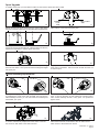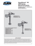
1
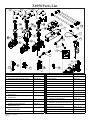
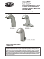
Aqua-FIT®
Serio SeriesTM
Sensor-Operated Lavatory Faucets
for Battery or Plug-In Installations.
®
Installation, Operation, Maintenance,
and Parts Manual
Patented and Patents Pending
Z6955-XL-S
Z6950-XL-S
Z6950-XL-IM-S
Sensor-Operated Battery-Powered
Lavatory Faucets
LIMITED WARRANTY
All goods sold hereunder are warranted to be free from defects in material and factory workmanship for a period of three years from the
date of purchase. Decorative finishes warranted for one year. We will replace at no costs goods that prove defective provided we are
notified in writing of such defect and the goods are returned to us prepaid at Sanford, NC, with evidence that they have been properly
maintained and used in accordance with instructions. We shall not be responsible for any labor charges or any loss, injury or damages
whatsoever, including incidental or consequential damages. The sole and exclusive remedy shall be limited to the replacement of the
defective goods. Before installation and use, the purchaser shall determine the suitability of the product for his intended use and the
purchaser assumes all risk and liability whatever in connection therewith. Where permitted by law, the implied warranty of merchantability
is expressly excluded. If the products sold hereunder are “consumer products,” the implied warranty of merchantability is limited to a
period of three years and shall be limited solely to the replacement of the defective goods. All weights stated in our catalogs and lists are
approximate and are not guaranteed.
Serio SeriesTM Faucets
1a.
1b.
1c.
2a.
2b.
Z6950 Spout Assembly
Z6955 Spout Assembly
Z6950-IM Spout Assembly
Z6950 Spout base gasket
Z6955 Spout base gasket
SPECIFICATION
Voltage:
6 VDC Series
[4 “AA” (Alkaline or Lithium) and/or external
power option]
Sensor Range:
Self Calibrated, dependent upon sink depth
and finish.
Operating Water
Pressure:
10-125 psi
Operational Water 33°F to 140°F (1°C to 60°C)
Temperature:
Aerator:
1.5 GPM Vandal-Resistant (Standard)
3a.
3b.
4.
5.
6.
Electronics Box with Solenoid - Z6950/55-XL
Electronics Box with Solenoid - Z6950-XL-IM
Aerator and Key
Mounting Kit
Batteries
OPERATION
1.) Invisible light rays are continually emitted from the faucet
sensor.
2.) When the user’s hands come into range of the sensor’s
detection zone, the beam is reflected back to the sensor’s
reciever, and activates the solenoid valve.
3.) After the user removes their hands, the absence of the
reflected light closes the valve. The circuit automatically resets
for the next user.
4.) If an object remains in view continuously, the faucet will
automatically shut off. The faucet will remain off until the object
is removed. After the object is removed, the faucet functions
normally.
IMPORTANT:
• All plumbing is to be installed in accordance with applicable codes and regulations.
• Water supply lines must be sized to provide an adequate volume of water to each fixture.
• Flush all water lines prior to valve installation to ensure proper operation. Particulates in the water can block small orifices within the valve which may
result in continuous running.
• The use of toothed tools during installation or service of the faucet or its components may lead to premature failure.
• FAUCET SENSOR COMMENCES AUTO RANGE CALIBRATION FOR 30 SECONDS UPON CONNECTING SENSOR TO ELECTRONICS
BOX. ENSURE FAUCET AND SINK BASIN HAVE BEEN INSTALLED, AND AREA IS IN THE FINAL OPERATING CONDITIONS BEFORE
CONNECTING SENSOR TO THE ELECTRONIC BOX.
FV563 Rev. C 5/28/15
Page 2
Prior to Installation:
The following tools may be necessary for installation:
Before installing your Zurn® Aqua-FIT® Faucet: the items listed
• Non-toothed Wrench
• Phillips Head Screwdriver
below should already be installed on site.
• Allen Wrench (M3)
• Allen Wrench (3/32”)
• Lavatory/sink
• Drain Line
• Hot and cold water supply line or pre-tempered water supply line.
If you are replacing an existing faucet or Aqua-FIT® shells, turn off water supply and remove the old faucet. Clean lavatory rim around the
mounting area for the new sensor faucet.
CARE AND CLEANING INSTRUCTIONS:
DO NOT use abrasive or chemical cleaners to clean faucets as they will dull the luster and attack the chrome or special decorative
finishes. Use only mild soap and water, then wipe dry with a clean cloth or towel. While cleaning the bathroom tile and floor, the
faucet and electronics should be protected from splattering of water, cleaner, acids and cleaning fluids that can damage the
sensor faucet.
Step 1. - Spout Installation
Sink or
countertop
Spout Gasket
Plate Gasket
Optional cover plate
(CP4 or -CP8)
Star Washer
Mounting Nut
1
1.1) Pass sensor connector cable and shank through gasket.
Align gasket with faucet bottom and press firmly together.
NOTE: For faucets with -CP4 or -CP8 suffix, pass sensor connector and shank through cover plate and fasten to the faucet with the
provided screws.
Plastic Mounting
Washer
2
1.2) Pass the sensor connector wire and shank through cover
plate gasket (if cover plate option is incorporated) and through the
hole in the sink and/or countertop. Orient black plastic mounting
washer with the slot facing up. Place mounting washer and star
washer over shank and secure the entire assembly to the lavatory
with the mounting nut.
3
1.3) Ensure that slot in plastic washer is facing forward. The
sensor cable must pass through slot in plastic mounting
washer. NOTE: Do not pinch or damage the sensor cable
during tightening of the nut.
Step 2.- Electronics Module Installation
-IM BATTERY
BOX
DO NOT MATE
ELECTRICAL SIGNAL
CONNECTOR AT
THIS TIME
Shank Gasket
Electronics Box
Hex Nut
Shank Gasket
Electronics Box
Hex Nut
4
5
2.1) Attach electronics module to the shank using the hex nut and gasket provided. Orient the electronics in a convenient location and
tighten hex nut. DO NOT USE THREAD SEALANT.
FV563 Rev. C 5/28/15
Page 3
Step 3.- Filter or Mixing Tee or Mixing Valve Installation
-MV
-MT
The supplied inlet filter must be
used with every faucet, unless a
mixing tee or mixing valve is
ordered.
8
7
3.1) The inlet filter is attached directly to the electronic module’s
water inlet. Tempered water is then supplied to the filter using a
standard 3/8” x 1/2” ball riser (supplied by others.)
3.2) The optional mixing tee assembly (-MT) or mixing valve (MV) have integral filters and back checks. These take the place of
the standard inlet filter when ordered. The mixing tee or mixing
valve outlet attaches to the electronics module with a 3/8” x 1/2”
ball riser (supplied by others). Hot and cold water is then supplied to the appropriate 3/8” compression inlets.
Step 4.- Connect Power
(Choose from the following: battery only, external ACA, P6000-HW6 with CWB, and/or External power with battery pack)
BATTERIES
9
SOLENOID Y
CONNECTOR
10
4.1) Battery Installation: Loosen the battery cover screw with the supplied allen wrench. Remove the cover and install the batteries
as indicated on the battery case. Replace the battery cover and secure. When installing an IM model, make certain that the supplied
solenoid Y connector is connected so that both solenoids will recieve power.
ACA
ACA
11
SOLENOID Y
CONNECTOR
12
4.2) ACA (Alternating Current Adaptor) Plug-In Installation: When using the -ACA plug-in power supply, attach provided inline
connector between sensor and electronics box to allow ACA connection. When installing an IM model, make certain that the supplied
solenoid Y connector is connected so that both solenoids will recieve power.
FV563 Rev. C 5/28/15
Page 4
-HW6
INLINE
CONNECTOR
-CWB
13
SOLENOID Y
CONNECTOR
14
4.3) HW6 (Hardwired 6V) Installation: When using the -HW6 power supply, attach provided inline connector between sensor and
electronics box to allow hardwired connection. When installing an IM model, make certain that the supplied solenoid Y connector is
connected so that both solenoids will recieve power.
-MJ
-HW6
6
18 AWG (MIN)
MAX LENGTH 40’
15
2.3) Ensure that arrows are aligned for each connector and fully
mate.
*NOTE: FAUCET SENSOR COMMENCES AUTO RANGE
CALIBRATION FOR 30 SECONDS UPON CONNECTING SENSOR
TO ELECTRONICS BOX. ENSURE FAUCET AND SINK BASIN
HAVE BEEN INSTALLED, AND AREA IS IN THE FINAL
OPERATING CONDITION BEFORE CONNECTING SENSOR TO
THE ELECTRONICS BOX.
Note: If connecting more than one spout it is recommended that
the -MJ (Multi Junction) is used.
FV563 Rev. C 5/28/15
Page 5
Adjustable modes and features selection:
To adjust features from default configuration, you must remove
the battery tray. Once battery tray is removed you will see the
switches.
Before adjusting switches when electronics box is first installed
or when replacing dead battery:
1. Temporarily install battery tray with fresh batteries installed
and hold in place for 30 seconds.
2. Remove battery tray and set switches
3. Re-install battery tray
All switches shown in default mode.
ON
OFF
Switch Position: 1
Purge (Hours)
Disable: Off
12: On
24: Off
48: On Time (Seconds)
30:
5:
10:
15:
60:
20 Minutes: Mode Select
Sensing Mode:
Metering Mode: Sensor Sensitivity
High:
Low:
Mode A:
Mode B: 1 2 3 4 5 6 7 8
2
3
4
5
Off
On
Off
On
Off
On Off
Off
On
On
Off
Off Off
Off
Off
Off
On
On 6
7
8
Off
On
Off
On Off
Off
On
On Off
Off
On
On Off
On Purge Features:
The purge switches can be configured for 4 modes of operation: Disabled (standard configuration), 12 hour, 24 hours, or 48 hours.
Purge water flow duration is 2 minutes. Note: Purge activation occurs every switch selected time (0,12, 24, or 48 hours) after last
activation.
Flow Time:
There are 6 optional time configurations: 30 seconds (standard), 5s, 10s, 15s, 60s, & “Less Time-out”. The “Less or No Time-out”
option actually ceases water flow (turns off) after 20 minutes to limit chance of water damage in the event a sink drain becomes
blocked .
Sensing Mode (DEFAULT):
During this mode the valve will shut off after hands are removed. If hands are not removed the time out delay will turn off the faucet
(ex: standard configuration is 30 seconds)) (See Sensing & Metering Mode flow chart on following page)
Metering Mode:
When hands are detected by the sensor, water will run for ‘ X’ seconds (standard configuration is 30 seconds) before turning off.
(See Sensing & Metering Mode flow chart on following page)
Sensor Sensitivity: (Default setting: Low):
There are 4 sensitivity options, which can be selected to achieve the optimal detection performance related to the sink material,
shape, & finish. The faucet sensor sensitivity is configured during pack-out but the mode can be changed upon installation to
optimize the performance within the sink. Sensor sensitivity and Modes A & B may be tried for difficult sink materials and shape.
NOTE: After a configuration switch change has been made, disconnect sensor cable from electronics box, wait 30 seconds, then
reconnect sensor cable and wait 30 seconds to allow the sensor to tune-in the sink characteristics.
FV563 Rev. C 5/28/15
Page 6
SENSING & METERING MODE:
SENSING MODE
METERING MODE
Sensor detects hands
No
Move hands closer to
faucet spout or closer to
bottom of sink
Yes
Water turns ON
No
Sensor detects hands
Yes
Move hands closer
to faucet spout or
closer to bottom of
sink
Water turns ON
No
Hands removed
from sensor view
Yes
Water stays ON as long
as hands are detected &
time limit per the period
set by
switches 3, 4, and 5
Sensor detects hand
removal
Water turns OFF
Sensor Detects Hands and water Turns on Once activated, water
flows for duration/period
set by
switches 3, 4, and 5
regardless if hands are
rem oved or not
Water turns OFF
Sensor Detects Hands and water Turn
TROUBLESHOOTING GUIDE:
POTENTIAL SITUATIONS
Sensor f aucet is not
activating or running
POSSIBLE CAUSES
Battery voltage low or no pow er
SUGGESTED SOLUTION TIPS
Change out batteries or verif y pow er provided by HW6 or ACA
If f aucet is hardw ired, voltage may be out of
allow able range.
Contamination in battery tray causing a voltage
drain
Sensor and electronic connector cable has
bent or broken pins
Sensor lens could have surface damage,
scratches, or deposit build ups f rom chemical
cleaners
Sensor lens could be obstructed by
environmental f actors such as high ref lective
surf aces or bright lighting conditions
Check voltage levels and verify w ithin recommended ranges.
Solenoid is not connected properly
Solenoid is lodged w ith debris or plunger is
sticking
Sensor f aucet does not
Sensor may not have had enough time to
activate af ter initial installation calibrate prior to a user or target trying to
initiate activation
Remove the battery tray and inspect f or visual signs of rust, w ater,
debris. Replace battery tray if these symptoms are f ound.
Check to see if pins are missing, bent, or broken. If yes, then the
electronic box needs replaced
Inspect the sensor lens underneath the spout tip. May require
cleaning w ith a damp cloth or sensor replacement
If this is the case, then adjust the dip sw itch settings f or sensor
sensitivity per the diagram on previous page (sw itches 7 and 8).
Direct sunlight into bow l may make the unit inoperable. Do not allow
direct sunlight into bow l
Place hands in sensor range. If clicking occurs, solenoid is
connected correctly. If no clicking occurs, disconnect the sensor
cable f rom the black box and w ait 30 sec bef ore reconnecting.
Once reconnected try activating again.
Check solenoid for debris and clean if necessary and reassemble
Disconnect the sensor and electronic box cables and w ait for 30
seconds. Reconnect the cables, but allow for another 30 seconds
before placing hands or a target w ithin the sensor range. You
should hear a click of the solenoid once calibration is complete.
Faucet runs continuously
Solenoid is lodged w ith debris
Check solenoid for debris and clean if necessary and reassemble
(longer than the selected time- Electronics box cable connector has bent pins Check to see if pins are missing, bent, or broken. If yes, then the
out that is programmed)
that are shorted
electronic box needs replaced.
Sensor f aucet is experiencing Sensor lens could be obstructed or
random activations w hen a
environmental f actors such as high ref lective
user or target is not w ithin
surf aces and/or bright sunlight conditions
sensing range
Change dip sw itch settings (sw itches 7 &8) f or sensor sensitivity
per the diagram and allow 15s f or calibration to occur.
Loosen the mounting nuts and try sliding the f aucet back in the
lavatory, sink, or counter top holes back tow ards the w all and
retightening. Could be detecting the grid drain in the sink bow l. Af ter
repositioning faucet, recalibrate sensor by unplugging & replugging
cable
Sensor f aucet is leaking
underneath the sink or
counter
Check and ensure the nuts and joints are tight and secure from the
supply stop all the w ay to the f aucet shank.
Mounting hardw are is not tightened
suff iciently (f aucet shank, electronic box,
supply hoses, etc)
Missing the w asher located in the solenoid
box nut w here it assembles to the faucet
shank.
Make sure the w ater supply stops are shut off . Check to ensure the
w asher is installed or damaged. If not, install w asher. If a w asher is
installed replace w ith new .
FV563 Rev. C 5/28/15
Page 7
Z6950 Parts List
6
7
8
13
19
21
22
20
P6000-HW6 WIRING
FRAM E/SAFETY GROUN D
G REEN/YEL LO W
VAC
N
I
BL UE (-)
WHITE
(N EUTRAL )
BLACK
(LINE)
RED (+)
17
18
9
11
Description
1a. Z6950 Spout Assembly with Sensor
Product No.
P6950-XL-S-1
6. 8” Cast Cover Plate w/Gasket
P6950-CP8
7. Z6950 Sensor As sembly
P6950-XL-EL
1b. Z6955 Spout Assembly with Sensor
P6955-XL-S-1
8. Mounting Kit
P6900-43
1c. Z6950-IM Spout Assembly with Sensor
P6950-XL-S-IM-1
9. Filter Kit
P6900-120
2a. Spout shank base for Z6950/Z6955-XL
P6950-XL-B
10. Filter Screen
P6900-MV-7
2b. Spout shank base on Z6950-XL-IM
P6950-XL-IM-B
11. Mixing Valve w/Filter
P6900-XL-MV
3a. Z6950 Spout base gasket
P6950-XL-42
12. Mixing Tee w/Filters and Back Checks
P6900-XL-MT
3b. Z6955 Spout base gasket
P6950-XL-44
13. Optional Plug-in Power Converter
P6900-ACA
4a. Electronics Box with Solenoid Z6950/55-XL
4b. Electronics Box with Solenoid Z6950-XL-IM
i. Y pipe adaptor for Z6950-XL-IM model
P6950-XL-B-L
14. Single Stainless Supply Hos e (XL)
P6900-SSH
15. Stainles s Supply Hos es (XL)
P6900-SH
ii. Mixing Handle for Z6950-XL-IM model
iii. Mixing handle plug/cap for
Z6950-XL-IM model
iv. Handle O-ring & Handle Screw for
Z6950-XL-IM model
5. 4” Cast Cover Plate w/Gasket
FV563 Rev. C 5/28/15
Page 8
P6950-XL-IM-B-L
16. Composite Mixing Valve Adaptor
P6900-MV-ADAP
P6950-XL-Y
17. Shank Connection Gasket
P6900-SG
P6950-XL-H
18. Solenoid Rebuild Kit
P6900-SRK
(Diaphram, plunger and plunger spring)
19. Sensor Inline Connector
P6950-XL-DC
P6950-XL-C
P6950-XL-OS
P6950-CP4
20. IM Solenoid Y Connector
P6950-XL-YC
21. -CWB Pigtail
P6900-CWB
22. -HW6 Power Supply
P6900-HW6
Spout Upgrade
To replace spout body, you must first turn water off, then remove spout with sensor cable.
16
Before removing the spout, disconnect the sensor cable below
the deck so that the cable head can be pulled up through the deck.
SPRING
LOCK
SIDE
SET SCREW
SIDE
Note location of set screw and spring lock.
18
Use supplied 3/32” hex wrench to loosen set screw. Screw will
retract into the base to eliminate loss. Using the same hex wrench,
depress the ball detent to release spout from base.
19
Lift spout and pull sensor cable through deck and base.
20
To reinstall faucet, first drop sensor cable of new spout through
the front of the base. Lower spout onto base inserting base nipple
into spout port.
17
21
Align spout so that the ball detent is between the 2 holes. Press
down and turn clockwise. Use hex wrench to back set screw out
to secure spout.
Sensor Assembly Replacement
23
22
With spout disengaged, sensor assembly can now be removed
by loosening the center screw with provided 3mm hex wrench.
With assembly removed, you can now install new assembly and
reassemble your spout.
Loosening screw will cause sensor assembly to back out of spout
body. It may be necessary to push cable from connector end to
aid in sensor assembly removal. Firmly press into pocket and
tighten screw.
Accessing the Solenoid
24
To service solenoid use phillips head screw driver to remove
the screws on both sides of the electronics box.
25
With screws removed, the electronics box can slide off and
allow access to the solenoid for service.
FV563 Rev. C 5/28/15
Page 9
ZURN INDUSTRIES, LLC. ♦ COMMERCIAL BRASS OPERATION ♦ 5900 ELWIN BUCHANAN DRIVE ♦ SANFORD NC 27330
Phone: 1-800-997-3876 ♦ Fax: 919-775-3541 ♦ World Wide Web: www.zurn.com
In Canada: ZURN INDUSTRIES LIMITED ♦ 3544 Nashua Drive ♦ Mississauga, Ontario L4V1L2 ♦ Phone: 905-405-8272 Fax: 905-405-1292
FV563 Rev. C 5/28/15
Page 10
Aqua-FIT® is a trademark of Zurn Industries, LLC.
Printed in the U.S.A.