1
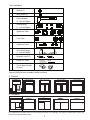
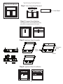
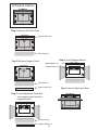
Installation Instructions VVS - Secret v.002 Patent Pending ® Making wires disappear Parts Included: Washer (2) Wing skrew (2) Mount bracket (2 - Left and Right) Panel bracket (2 - Left and Right) Appliance Tubes Tube Caps Appliance Panel False Panel Hinge (2 - Left and Right) Magnetic catch (2) Velcro (12” strip) Female Male Quick release knobs (4 pairs) You are likely to have a model similar to these: A. Framed 24” 24” 30” 30” 24” 24” 30” 30” B. Unframed The standard VVS will work with most all false panel cabinets 24” and larger. For cabinets smaller than 24”, you will need to cut the panel down to size. 1 Summary Instructions Step 1: False (Faux) Panel Removal ← False Panel Step 2: Support Panel Addition Add support beams (not included) if backing drywall or it not greater than 1/4” wood Step 3: Appliance Panel Assembly Adjustment Wing Screw ← Framed Cabinet ← groove ↑ Washer Step 4: Appliance Panel Installation 2 Summary Instructions (cont.) Step 5: Quick Release Knob Set Up Measure the inside hole and cut two sheets of paper to the size for a template. If false panel measures less than 5” in height, a diagonal knob layout will not work. If the length of the panel measures less than 24” do not include 4 cord wrap pairs. Place hinges on template, then knobs to determime bestspace for each knob pair. Mark each knob by making a hole. Step 7: Apply velcro male strip to gap between knobs. Apply female (fuzzy) side to plug casing (away from the plug prong plane) or cable for a plugged model. Female Male Female Place template on false panel and transfer marks. Male Female Add knobs to the false panel Warning: Make sure the velcro does not come near the plain holding the plug prongs. Step 6: Hinge and Panel Attachment Velcro too close to plug plane. Add hinges to opening and attach to false panel. (Important: Pre-drill holes) Plug prong plane GOOD 3 BAD 22” IMPORTANT 9” 4 7/8” 4 1/2” 16” 10” ** Rounter or sand edges to opening 14 5/8” ** IMPORTANT: To ensure all curling and flat iron handles can sit inside the cabinet, the back edge of the appliance panel must sit a minimum of 9” from the inside cabinet. If you have a center drain and need the panel to go back further past the center pipe, drill a 1 3/4” half circle into the appliance panel to gain an additional inch. NOT INCLUDED Support beams Drywall screws for support beams 6 Screws to mount the mount bracket are not included. The back of a bathroom cabinet construction is not standardized. The cabinet design must be evaluated to determine the best installation method. DO NOT use standard screws to mount brackets into drywall. 4 Step 1: False (Faux) Panel Removal Each cabinet company or maker installs false panels differently. False panels are often stapled, glued, screwed, snapped, or secured using support panels to secure them to the frame. A licensed contractor should determine how your false panel is secured to the frame to then remove it carefully. * If staples or nails are clipped, use a nail punch to push the edge into the wood. You can then use filler to create a smooth surface. Ensure the environment is void of anything sharp that can catch on skin or clothes. Step 2: Support Beam(s) Addition (since one or two may be used) Make sure you have a solid and secure surface to install the mount brackets. If you are installing on drywall or 1/4” wood, we recommend you add wood support beams either vertically or horizontally to prevent any movement. Each bracket should be screwed to the wall or support beam using 3 screws suited for the type of surface it will mount to (screws not included). Step 3: Appliance Panel Assembly a. AddThe Brackets to the Appliance Panel VVS system provides two panel brackets for mounting. Place each panel bracket on the appliance panel using the second row of the brass insert holes. The arm portion of the bracket should point away from the false panel. If completed correctly, the appliance panel will set at a 45 degree angle on a level-mounted panel bracket. b. Slide Appliance Panel in Wall Brackets Slide the appliance panel and its brackets into the mount brackets. The top of the panel should set below the base of the sink, against the pipe. Remember, the panel must be far enough inside the cabinet to allow all handles to sit within the cabinet walls. c. Secure Appliance Panel To secure the appliance panel, insert the wing screws with washers into the adjustment groove of the panel bracket and secure with the screw nut provided. Tightening the wing screws into the fixed screw nuts will secure th appliance panel to the mounted panel bracket. d. Add Tubes and Caps Once the panel is constructed, place each ventilated tube into the corresponding hold in the appliance panel. Then attach each ofthe 2” and 1.5“ caps security with a push and a twist. MAKE SURE ALL 2” AND1.5” TUBES ARE CAPPED. 5 Step 4: Install Appliance Panel If using a support beam(s), use six size 10, 1” screws (not included) to mount the panel brackets directly to the support beam(s). If mounting directly to drywall, use the appropriate screws designed for maximum support and pressure. Step 5: Add Quick Release knobs to False Panel A. Finish the Panel and Inside Edges Often the back of the panel and inside edging of the false front opening are left unfinished. Since this will now be visible, we recommend you sand, stain, melamine, and/or paint these locations to suite the remaining cabinet. If the inside of the false panel has a recessed surface, fill and modify to create an even surface. This is necessary to achieve maximum room for wire wrapping. b. Add Quick Release Knobs Installing the quick release knobs requires some thought because we are not able to provide templates given there is no standardization with respect to false panels. If there is a depression or design to the panel, we recommend you fill it. The goal is to maximize the panel's surface area. Also, please let us know if you would like laminate ($9.99) to cover the inside face of the panel. We carry it in both black and white. In order to place the knobs in a functional and effective location, we recommend the following methodology: Step 1: a. Measure the length (L) and height (H) of the opening to the false panel. b. Then take two pieces of paper and tape them together to match the length (L). c. On the paper measure mark the height of the false panel (H) and cut the paper to match the size of the false panel opening. Step 2: Place the knobs on the piece of paper in the order and formation that will grant you enough room to wrap all cords. Use a pen or sharp tip to punch a hole for each opening. Note: Each quick release knob measures a total of 2.5" in length. To be effective, opposing knobs need to utilize between 8 and 9 inches width to successfully wrap an appliance cord. If the height of your panel is 5” and the length is 24”+, you are likely to fit 4 cord wrap pairs in a diagonal alignment. If the height is smaller than 5”, you will need to pair your quick release knobs in a horizontal fashion. Now the length of the panel will determine how many pairs you can wrap. Most commonly you are looking at 2 or 3 pairs at most with smaller panels. FYI, you need your opening to be at least 19" wide to allow the use of two quick release pairs. The bigger the false panel opening, the easier it will be for your client to wrap and close the false panel. 6 Step 6: Add hinges to opening and false panel The hinges are designed to install inside the false panel opening and attach to the false panel. Place the hinge against the bottom corner of the opening and add a screw to the top hole, and one to the bottom located on the 3/4” wood. Do this for both hinges. Close both hinges. Measure the dimensions of the false panel. (L1 x H1) Measure the dimensions of the false panel opening. (L2 x H2) Subtract the length and height differences and divide by 2 to determine the amount of overlap. (L1 - L2)/2 = Left and Right gap (H1 - H2)/2 = Top and Bottom gap Place the false panel over the opening in the exact location and mark the top hole of the hinge on the panel. Open the hinge completely and place a screw in the top hole. Do this to both sides and ensure the panel closes in the correct spot. If satisfied screw in the second hole. If hinges are torqued, they will not close. Try loosening screws and adjusting to ensure the hinge is straight. Step 7: Add Velcro to distance between knob pair Included in the kit is a 12” velcro strip. Cut a piece to fit between each two quick release knobs. The male side has vertical fibers while the female side is fuzzy. Place the male side on the false panel surface. Place a smaller female strip on the side of the plug, keeping it away from the plane containing the plug prongs. If your appliance is designed to be continuously plugged and you only wrap the remaining cord, wrap the female velcro around the piece of cord that is last to be wrapped around the knob to secure it in place. Make sure to wrap more than 361 degrees of velcro tape for the female. This will ensure that this piece doe not come off. Step 8: Adding a Latch We recommend you install magnets on the top right and left corners or place one in the center. When deciding the best location, aim to maximize the space between quick release knobs. 7 Custom Cabinet Considerations When a cabinet is being built to meet a clients specifications, we recommend going with a vanity that provides a panel opening that is 22" or more in length. Smaller openings will work, but the larger the false panel opening, the easier it will be for your clients to manage four appliance cords. We also recommend a false panel opening whose height is 5.5". This will create a cord panel that isn't crowded and makes two rows of cords easier to manage. Also, cabinet makers should provide a .75" piece of wood measuring 5" in height or more and across the back of the cabinet to make mounting the brackets easier. This will eliminate the need to install additional support beams. FYI, the average weight of 4 appliances plus the wood and brackets weighs less than 10 lbs. ** Round (router) the top and bottom edges of the opening (specifically the top outside edge and the bottom inside edge). People will reach in and out of the opening to access their appliances. Rounded edges allow more accessibility for the appliances. 8 Unframed Cabinet Step 1: Remove the False Panel ←Support Panel (b) ← False Panel (a) Step 2: Remove Support Panel Step 4: Install Support Beams Support Beams (c) Support Beams (c) ←False Panel (a) ←Support Panel (b) Step 3: Install Appliance Panel and cut support panel into two support beams ← False Panel (a) ← Support Beams (c) 9 ← ← Step 5: Convert Panel into Door Unframed Cabinet When a cabinet is unframed with a false panel, there is usually a supporting panel behind it. In order for the false panel to turn into a door, you must create a minimum 5” opening in height with a 3/4” deep rail to mount the hinge and door. To achieve that design, you may have to trim the support panel to provide an upper and lower support beam as described in the Unframed Cabinet diagram. Round (router) the top and bottom edges of the opening - specifically the top outside edge and the bottom inside edge. This reduces the chances of hitting your hand as it goes in and out of the opening to manage tools. General Considerations: * The VVS does not work with rectangle sinks * The VVS does not work with bathroom cabinets that do not have a false panel * The opening to false panel should be at least 5” in height to allow blow dryers which are usually between 3.5”-4” in diameter to clear. * Insert the blow dryer horizontally, through the false panel opening, into the 3“ hole, then rotate vertically. * A standard false panel on a 24“ cabinet with a minimum height of 5” will support 2 wrapped cords spaciously, and 3 snuggly. * A standard false panel on a 30” cabinet with a minimum height of 5” will support 4 wrapped cords. 10 WARNING: TURN-OFF ALL APPLIANCES WHEN THEY ARE NO LONGER IN USE. POJJO Inc. 18208 Preston Rd. #D9-136 Dallas, TX 75252 [email protected]


![Intra-Pod instructions.ppt [Read-Only]](http://vs1.manualzilla.com/store/data/007247390_1-f78b03339eb740c14aa24b2c59786747-150x150.png)