1
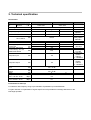
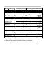
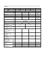
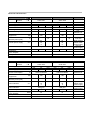
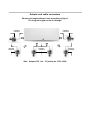
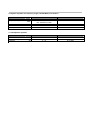
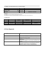
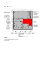
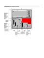
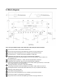
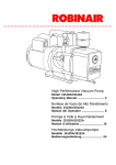
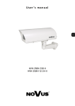
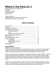
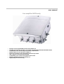
user manual
Line amplifier NVD-family
o
o
o
o
o
o
o
o
o
Remote control by DOCSIS-Transponder DOTRA 1.0
DOCSIS-Transponder DOTRA 1.0 available with DOCSIS and EURO-DOCSIS-modem
Comfortable user interface by web browser, HTML based
Ethernet port for local operation 10Base-T
Electronic operation of all adjustment elements by remote
ICS = Ingress Control Switch 0/6/31dB
Comfortable error location and system state check
Modular DOCSIS transponder DOTRA 1.0
High quality die cast housing
Table of contents
1. Precaution
21
2. Technical specification
22
3. Plug-in modules
28
4. Error diagnosis
30
5. In-/Outside
31
6. Block diagram
33
7. Safety advices
34
1. Precaution
This unit has been manufactured to satisfy the international safety standards.
Please read the following safety precautions carefully.
OVERLOADING
Do not overload a wall outlet, extension cord or adapter as this may result in
fire or electric shock.
LIQUIDS
This unit shall not be exposed to dripping or splashing objects also
filled with liquids, such as vases, shall not be placed on the gadget.
CLEANING
Disconnect the unit from the main supply before cleaning. Do not use any
kind of solvents to clean the unit only use a soft-dry cloth.
EARTHING
Take note of the official advices of antenna earth grounding.
LOCATION
Place the unit indoor in order not to expose to lightening, rain or sunlight.
Additional safety advice at the end of this user manual!
2. Technical specification
Downstream
Type:
articleEuroDOCSIS …-ED
…-D
no.
DOCSIS
Final stage
Frequency range
Gain IN – OUT1
Gain
IN –
OUT1,OUT2
NVD 8128R…
NVD 8128…
5700 1590
5700 1591
5700 1592
5700 1593
1x Push Pull Power Doubler Hybrid
min.
typ.
max.
dB
27
28
dB
2x23,5
Ripple
Input attenuation
Interstage equalizer
0 point loss
Interstage-attenuation
or alternatively ALC via
QAM CMTS Kanal
dB
dB
dB
dB
dB
±0,5
0…15,5
0…20
±0,5
0/6
dB
±3,5
Test point input
dB
-20
Test point output
dB
-20
Return loss
input
Return loss
output
Noise
Output level
CSO > 60 dB / 42 Ch.
Output level
CTB > 60 dB / 42 Ch.
dB
dB
dB
dependent on
Diplexer
47/85-1000
MHz
29
by use of
2-way splitter
VM 202-2
±0,7
18-1.5dB per Oct.
min. 13 dB
18-1.5dB per Oct.
min. 13 dB
5
dBµV
113
dBµV
111
Remarks
0,5 dB steps
at 1000MHz
1 dB steps
accuracy
±0,5 dB
F-connector,
female,
internal
5…1000MHz
F-connector,
female,
internal
5…1000MHz
6
Instructions for start-up:
For networks with frequency range up to 606 MHz: Equalization input with EZM 606
For gain reduction or equalization of signal slope first use if possible the interstage attenuator or the
interstage equalizer.
Type:
articleEuroDOCSIS …-ED
…-D
no.
DOCSIS
Final stage
Frequency range
Gain IN – OUT1
Gain
IN –
OUT1,OUT2
NVD 8138R…
NVD 8138…
5700 1594
5700 1595
5700 1596
5700 1597
1x Push Pull Power Doubler Hybrid
min.
typ.
max.
MHz
dB
38
dB
2x33,5
Ripple
Input attenuation
Interstage equalizer
0 point loss
Interstage-attenuation
or alternatively ALC via
QAM CMTS Kanal
dB
dB
dB
dB
dB
±0,5
0…15,5
0…20
±0,5
0/6
dB
±3,5
Test point input
dB
-20
Test point output
dB
-20
Return loss
input
Return loss
output
Noise
Output level
CSO > 60 dB / 42 Ch.
Output level
CTB > 60 dB / 42 Ch.
dB
dB
dB
dependent on
Diplexer
47/85-1000
37
39
by use of
2-way splitter
VM 202-2
±0,7
18-1.5dB per Oct.
min. 13 dB
18-1.5dB per Oct.
min. 13 dB
5
dBµV
113
dBµV
111
Remarks
0,5 dB steps
at 1000MHz
1 dB steps
accuracy
±0,5 dB
F-connector,
female,
internal
5…1000MHz
F-connector,
female,
internal
5…1000MHz
6,5
Instructions for start-up:
For networks with frequency range up to 606 MHz: Equalization input with EZM 606
For gain reduction or equalization of signal slope first use if possible the interstage attenuator or the
interstage equalizer.
Upstream
Type:
articleEuroDOCSIS …-ED
…-D
no.
DOCSIS
Final stage
NVD 8128…
5700 1590
5700 1592
min.
Frequency range
Gain, switchable
OUT1 – IN
Ripple
Attenuation
Slope
MHz
NVD 8138R…
5700 1595
5700 1597
dependent on
Diplexer
5 - 47/65
23 / 31
dB
dB
±0,7
0…15,5
±0,9
dB
dB
0…15,5
dB
20 / 28
Remarks
max.
22 / 30
dB
Return loss
dB
input
Return loss
dB
output
Noise
dB
Output level
DIN 45004A1
dBµV
(IMA 2. Ordnung,-60dB)
Output level
DIN 45004B
dBµV
(IMA 3. Ordnung,-60dB)
Output bit error rate
at 120dBµV
(2carrier: 16QAM,8MHz
BER
1carrier: 16 QAM,
3,2MHz)
carrier-tointermodulation ratio at
dB
output level
115 dBµV
Output bit error rate
at 115 dBµV
BER
(4 carriers; QAM 64;
5,12 Msym/s)
Output modulation error Absch
nittsratio at 115 dBµV
MER /
(4 carriers; QAM 64;
dB
5,12 Msym/s)
Insertion loss
dB
passive
dB
5-65 MHz
Insertion loss
dB
85-1000 MHz
NVD 8128R… NVD 8138…
5700 1591
5700 1594
5700 1593
5700 1596
1x Push Pull Hybrid
typ.
0,5 dB steps
reference:
65MHz
0,5 dB steps
18-1.5dB per Oct.
min. 13 dB
18-1.5dB per Oct.
min. 13 dB
10
11
114
114
119
119
1*10
-6
1*10
-8
39
2,5
3,0
until 65 MHz
> 35
from 85 MHz
> 40
until 65 MHz
1,2
1,5
from 85 MHz
Electrical characteristics
Type:
article-no. EuroDOCSIS …-ED
…-D
DOCSIS
Power supply type
Power supply
Power connection
Cord length
Power consumption
Hum modulation
suppression
Remote current
(Remote power path)
Internal power supply
VAC
dB
m
NVD 8138…
NVD 8128…
5700 1590
5700 1594
5700 1592
5700 1596
switch-mode power supply
min.
typ.
max.
min.
typ.
max.
185
230
265
185
230
265
EU power plug
EU power plug
1,3
1,3
W
25
28
dB
>60
>60
10
A
VDC
Power indicator
ambient temperature
Impedance
Input / Outputs
Safety acc
EMC
°C
Power supply
Current consumption
Hum modulation
suppression
Remote current
(Remote power path)
Power indicator
VAC
A
LED green
+50
75
EN 60065
EN 50083-2
EN 60065
EN 50083-2
VDC
10
24
12
5
24
12
5
LED grün
LED grün
-20
Remarks
50 Hz
incl.
DOTRA 1.0
>60
10
A
Ohm
+50
75
>60
dB
°C
-20
15 A fuse
triple voltage
switch-mode
power supply
LED on
power supply
NVD 8138R…
NVD 8128R…
5700 1591
5700 1595
5700 1593
5700 1597
switch-mode power supply
min.
typ.
max.
min.
typ.
max.
28
50
70
28
50
70
view diagram
view diagram
below for details
below for details
Power indicator
ambient temperature
Impedance
Input / Outputs
Safety acc
EMC
LED green
-20
Ohm
Type:
article-no. EuroDOCSIS …-ED
…-D
DOCSIS
Power supply type
24
12
5
50 Hz
incl.
DOTRA 1.0
10
24
12
5
Remarks
+50
-20
triple voltage
switch-mode
power supply
LED on
power supply
+50
75
75
EN 60065
EN 50083-2
EN 60065
EN 50083-2
15 A fuse
Remote supply current in dependence of remote supply voltage
NVD 8138 R-ED / NVD 8138 R-D
NVD 8128 R-ED / NVD 8128 R-D
1,4
Remote supply-current I eff / A
Remote supply-current I eff / A
1,2
1
0,8
0,6
0,4
0,2
1,2
1
0,8
0,6
0,4
0,2
0
0
20
30
40
50
60
70
80
20
30
40
50
60
70
80
Remote supply-voltage Ueff / V
Remote supply-voltage Ueff / V
Mechanical data
Type:
Body dimensions
BxHxT
Weight
mm
Number of inputs 1)
Stk.
1
Number of inputs 1)
Stk.
1 (3)
Number of test points
Stk.
3
Potential equalization
top cover screws
Stk.
type of protection
protection class
Remarks
kg
251 x 256 x 124
4,4
PG11
(5/8” with
adaptor)
PG11
(5/8” with
adaptor)
F-female
vertical
internal
M4-Erdungsschraube an Druckgußgehäuse
2
4 mm
allen key
IP 65
II
1) Take note:
For the connection with 5/8“-fittings please use the adapter PG11m-5/8f (article-no.: 5700 0204)
Attention!
The centre conductor of the input and output terminals and the coaxial cable can carry remote supplyvoltage.
At mounting of cable fittings PG 11- or 5/8”-adapters remote power must be switched off.
For gain reduction or equalization of signal slope first use if possible the interstage attenuator or the
interstage equalizer.
Adapter and cable connectors
Shorten pin length without a burr according to figure!
Too long pin length results in damage!
min29mm
max32mm
min29mm
max32mm
min27mm
max30mm
min21mm
max23mm
Abb.: Adapter PG 11m – Ff (article-no. 5700 1082)
min27mm
max30mm
3. Plug-in modules
3.1 Diplex-filter RLK 230, RLK 265
RLK 265
RLK 230
Type:
Article No.
10161 588
10161 589
Frequency range
MHz 5 - 30 / 47 - 862
5 - 65 / 85 - 862
Insertion Loss
dB
1
1
For each amplifier you must use 2 pcs. of diplex-filter
Remarks
per diplexfilter
3.2 AGC-module AGC 203
Type:
Article No.
Frequency range
Insertion loss
Control ange
Note
AGC 203
10161 355
5 - 862
5
±3
MHz
dB
dB
using the AGC-module, amplification will be reduced by 5 dB (mid-position)
3.3 Equalizer-module EZM 606, EZM 862
Type:
Remarks
3.6 System equalizer for frequency range (740-862 MHz) accentuation
Type:
Article No.
Frequency range
Equalization
Basic attenuation
Linearity
MHz
dB
dB
KD 731
5700 1431
5 - 720 MHz 3 dB
740 - 862 MHz 0,7 dB
2,3
0,8
± 0,2
Remarks
in range 720 – 862 MHz
at 862 MHz
3.7 Deemphasis equalizer
Type:
Article No.
Frequency range
Equalizer
MHz
dB
DEM 10
5700 1356
47 - 862
0…10
Remarks
at 47 MHz
3.11 Adaptor for module position (X), (Y), see block diagram
Remarks
ID 100
10161 637
Type:
Article No.
Frequency range
Attenuation
MHz
0 - 862
dB
0 - 20
dependent on used PAD
Take note:
The adaptor ID 100 is standardly delivered with PAD 6 L.
This adaptor can also be used with equalizer moduls of the EZP-/EZL-series and KD 731.
3.12 Spare parts
Type:
0dB jumper
Article No.
3530 0381
Type:
Fuse 15A
Article No.
1610 0109
Jumper return path
amplifier
1610 0093
Skrew for
connection terminal
2580 0129
Screw terminal block
voltage feed
1600 0125
not listed in catalogue
Return path amplifier
Remarks
3530 0297
not listed in catalogue
Remarks
4. Error diagnosis
possible errors:
Error cause:
LED off
connected power plug? power supply or fuse fault
No gain
power supply or fuse fault, amplifier fault, return way not
plugged in or at wrong position
level attenuator or slope attenuator low, interstage loss at the
6dB position
Controller-pcb plugged in correct? All pins connected in the
socket?
Controller-pcb plugged in correct? Is there a network
connection at local access? Is the Cable Modem logged into
the CMTS? Is there access to the user interface?
Missing or to high or to low Up- or Downstreamlevel
Low gain
No reaction of the DOCSIS modem
5.3 Fernspeisung / remote powering
NVD 8xxx RP: Fernspeisepfad-Konfiguration mit Hilfe der Sicherungseinsätze /
2 Sicherungen im Steckplatz (Q1 und Q2) für einen HF-Anschluss dürfen nicht gleichzeitig
eingesteckt sein!
Die Richtung der Fernspeiseversorgung kann mit Hilfe der eingesetzten Sicherungen
konfiguriert werden ( siehe Seite 3: Stromlaufplan)
5. In-/Outside
5.1 Adjustments and positions for jumpers and PAD’s
Take note:
NVD-series needs PAD’s of length 25,4 mm (1”)
*At the positons for Interstage-attenuation
modules of EZP-/EZL-series or KD 731 could be
also plugged in
5.2 Adjustments and positions for modules
6. Block diagram
Short description NVD 8128 (E)D / NVE 8128 R-(E)D / NVD 8138 (E)D / NVD 8138 R-(E)D
1
Input test point -20dB, F-socket internal, bidirectional
2
Plug-in slot for input and line-out with splitter type VM 202-2 or tap type AM 201-XY
3
Plug-in slot for return path diplexers for 30 or 65 MHz; Type: RLK 230, RLK 265
4
Input attenuation 0…15.5dB, electronically adjustable in 0.5dB-steps
5
Equalization 606 or 862 MHz, plug-in slot for module EZM 606 or EZM 862.
At this plug-in slot there is also the possibility to use an ID 100 with EZP- or EZL-module or an
ID 100 with KD 731.
6
Interstage equalizer 1000MHz, 0…20dB, electronically adjustable in 1dB-steps.
7
Equalization 606 or 862 MHz, plug-in slot for module EZM 606 or EZM 862.
At this plug-in slot there is also the possibility to use an AGC-module type AGC 203, an ID 100 with
EZP- or EZL-module or an ID 100 with KD 731.
8
Interstage attenuation, with PAD’s in 1dB steps selectable.
At this plug-in slot there is also the possibility to use an EZP- or EZL-module or an KD 731.
9
Interstage attenuation, electronically 0/6dB, alternatively ALC (only if registered with CMTS)
10
GaAs-FET power doubler hybrid
11
Tap modem receiving data line RX
12
Plug-in slot for return path diplexers for 30 or 65 MHz; Type: RLK 230, RLK 265
13
Out test point -20dB, F-socket internal, unidirectional
14
Plug-in slot for OUT1 and OUT2 with splitter type VM 202-2 or tap type AM 201-XY
15
Plug-in place for ingressfilter, e. g. NHP 15.
16
Return path test point -20dB, F-socket internal, unidirectional
17
Return path ingress switch, 0/6/31dB
18
amplification switch 22/30dB
19
preamplifier 8dB
20
Tap modem transmitting data line TX
21
Return path equalizer 65MHz, 0…15,5dB, electronically adjustable in 0.5dB-steps.
22
Return path amplifier push-pull hybrid plugable, contained in the scope of supply.
23
Return path attenuation, 0…15,5dB, electronically adjustable in 0.5dB-steps.
24
alternative Tap modem transmitting data line TX, assembly variant on request!
25
DOTRA 1.0 EURO-DOCSIS or DOCSIS transponder
7. Important Safety advice
Please read these safety advice’s carefully before installing or putting into service your equipment and follow their
instructions.
The equipment may only be used in dry rooms. In humid rooms or outdoors there is a danger of shortage (caution:
risk of fire) or electric shock (caution: danger of life).
Choose the place of installation or mounting so that under no circumstances liquids or objects can get into the
equipment (e.g. condensation, water coming from leaky roofs or watering etc.).
Never expose the equipment to direct sun and prevent every other source of heat from coming near the equipment
(e.g. heaters, other electrical equipment, chimney etc.)
Ventilating slots and dissipaters are important parts of the equipment. For devices that are equiped with
dissipaters or ventilating slots it is therefore absolutely necessary to make sure that they are under no
circumstances covered or blocked. Also care for a generous air circulation around the equipment. In this way you
avoid possible damages to the equipment as well as a risk of fire caused by overheating.
In order to prevent your equipment from damages and to avoid possible consequential damages the devices
foreseen for wall mounting may only be installed on flat ground.
In order to avoid dangerous overvoltages (e.g. risk of fire and danger of life) the earthing of the connected devices
must be considered. Especially the VDE-regulation 0860 (corresponding to EN 60065) and the relevant
regulations for the installation and operation of antennas and antenna systems according to VDE-regulation 0855
(corresponding to EN 50083 or EN 60728) must be observed.
The place of installation or mounting must allow a safe laying of all the cables connected.
Power supply cables as well as feeder lines may not be damaged or squeezed by objects of any kind.
Furthermore, it is absolutely necessary that cables do not come near any source of heat (e.g. heaters, other
electrical equipment, chimney etc.).
Design the place of installation or mounting so that the power plug can be reached and pulled out of the socket
easily in case of danger. Choose the place of installation or mounting considering that children may not play
unsupervised near the equipment and its connections.
Before opening the equipment pull out power plug or remove power supply, otherwise there is danger of life. This
is also valid for cleaning the equipment or working on the connections.
Repairs on the equipment may only be carried out by specialists observing the valid VDE-Regulations.
Provided that an exchangeable fuse exists the power plug must be pulled out before changing the fuse. Defective
fuses may only be replaced by fuses that comply with the standards and have the same nominal value.