1
Coastal Industries Inc.
FAX NO.
(904) 641-1697
P.O BOX 16091
JACKSONVILLE, FLORIDA 32245
TELEPHONE NO.
(904) 642-3970
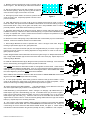
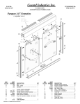
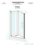
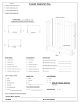
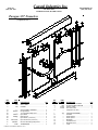
Paragon 3/8” Frameless
( exploded view )
KEY
LETTER
A
B
C
PART
NUMBER
651
643
650
D
d1
d2
d3
d4
d5
d6
——
CP652C
---PN3401
832HEX
---8321875SS
E
F
638PHPT
5172B
DESCRIPTION
QTY
SILL .......................................................... 1
WALL JAMB ............................................. 1
HEADER .................................................. 1
GLASS PANEL ASSEMBLY.......................
Hanger Bracket ............................................
1/4” Flat Head Phillips Screw ......................
Nylon Roller ..................................................
Roller Screws ..............................................
Nylon Sleeve, ( not shown ) ..........................
Nylon Set Screws ( not shown ) ....................
2
2
6
2
2
2
2
#6 x 3/8” Self Drilling Phillips Screw ............. 2
JAMB BUMPER ........................................
4
PARAGON 3/8” FRAMELESS BYPASS 04-20-18
KEY
LETTER
G
H
I
J
K
L
L1
L2
L3
L4
L5
L6
L7
PART
NUMBER
8112
1329
C375G
C494B
---T24
----------------------
DESCRIPTION
QTY
INSTALLATION SCREWS ........................ 6
PLASTIC SCREW ANCHOR .................... 6
TRACK GUIDE ......................................... 1
SILL SEAL VINYL ..................................... 1
(designation not used) ................................
TOWEL BAR ASSEMBLY .........................
Towel Bar ................................................
Plastic Bushing ........................................
Plastic Spacer .........................................
Back Plate ................................................
Towel Bar Screw ......................................
Back Plate Cover .........................................
Collar .......................................................
2
1
2
4
2
2
2
2
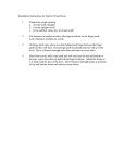
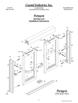
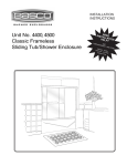
1. Measure the base opening along center of shower curb as
shown in figure 1, then trim Sill (A) to measurement obtained.
2. Trim the Vinyl Seal (J) to an inch and one eighth (1-1/8”) less
than the base opening. Slide Vinyl Seal (J) into the Sill’s receiver as shown in figure 2 and center it on the Sill.
3. With high lip toward exterior of enclosure, position Sill at
center of shower curb. Temporarily tape Sill to shower curb to
prevent movement.
MEASURE BASE OPENING
figure 1
figure 2
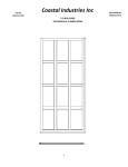
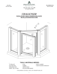
4. Place Wall Jambs (B) on to ends of Sill (A) and up against shower walls as shown in figure 3.
Plumb the Jambs, then pencil mark their installation holes locations on the shower walls (3 per jamb).
Remove Wall Jambs. Using a 3/16” glass / tile drill bit, drill 1” deep installation holes in locations
previously marked. Insert Plastic Screw Anchors (H) into holes.
5. Reposition Wall Jambs (B) as before and secure Jambs to shower walls using three (3) 8112
Installation Screws (G). Make sure to attach Panel Bumpers (F) to top and bottom installations holes
as shown in exploded view - sheet 1. Please note that notches on bumpers are positioned so as to
accept glass insertion, as shown in figure 4.
figure 3
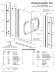
6. Measure the wall to wall opening at top of Wall Jambs and cut the Header (C) to the measurement
obtained. Position and install the Header over the Wall Jambs.
7. Attach Hanger Brackets as shown in exploded view - sheet 1 and figure 5 this sheet. Begin by
inserting a Nylon Sleeve (d5) into the glass panel holes.
Next, screw in two Nylon Set Screws (d6) onto the Hanger Bracket (d1) as shown in figure 5 (the
purpose of nylon set screws is for leveling adjustment of hanger bracket so it will not “see saw” on
glass) adjust as required.
Position Hanger Bracket onto the Glass Panel and secure to glass using a 1/4” Phillips Flathead Screw
(d2). Finally install the Roller (d3) as shown and secure with a Hex Screw (d4). Repeat step for the
remaining Hanger Brackets.
figure 4
8. Install the outside Glass Panel (D) by lifting the Panel up and into the Header (B). Lower the Panel
into the Track Guide (I) and engage the Rollers (d3) with the roller track.
Slide outside Door Panel into Wall Jamb located on wall opposite of shower head. Check Panel to
make sure that it is parallel to the Wall Jamb. If it is not, remove the Door Panel and adjust the rollers
either up or down by loosening the Rollers Screws and sliding the Rollers. When satisfied with outside
Door Panel alignment, proceed with inside Door Panel installation.
When satisfied, slide inside Door Panel into Wall Jamb located on shower head wall and check for
alignment with Wall Jamb. Adjust Rollers as necessary.
figure 5
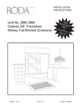
9. To insure proper operation, Track Guide (I) must be centered on Sill (A) when installed. Locate
center of Sill, position the Track Guide on the Sill and using holes on Guide as templates, secure
Guide to the Sill using two 638phpt Self Drilling Screws (E) as shown in figure 6.
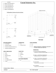
10. Before beginning Towel Bar installation . . . note that Towel Bars (L1) are attached on the same
side as the Nylon Rollers (d3), as shown in the exploded view - sheet 1.
Install Towel Bars (L), see exploded view - sheet 1 and figure 7 on this page. Slip a Back Plate (L4), a
Plastic Spacer (L3) and a Sleeve Bushing (L2) onto a Towel Bar Screw (L5) as shown in figure 7.
Insert it into the glass hole as shown and attach one end of a the Towel Bar (L1) to it ( do not forget
Plastic Spacer {L3} and Collar {L7} ). Attach the other end of the Towel Bar onto the Glass Panel.
Tighten down on screws to secure. Cover the screws by placing a Back Plate Cover (L6) over the Back
Plate (L4). Repeat step for the remaining Towel Bar.
figure 6
11. Run a bead of clear mildew resistant caulking down the full length of each Wall Jamb outside
where the Jambs meet the Walls. Now run a bead outside where the Sill meets the curb. Finally, run
a bead along the crevice where the Wall Jambs straddle the Sill, see figure 3. Follow caulking
manufacturer’s instructions before using shower (normally 24 hours). Installation is now complete.
GLASS HOLE
figure 7
PARAGON 3/8” FRAMELESS BYPASS 04-20-18