1
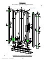
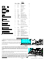
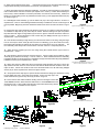
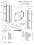
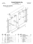
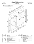
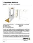
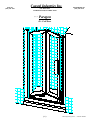
FAX NO.
(904) 641-1697
Coastal Industries Inc.
P.O BOX 16091
JACKSONVILLE, FLORIDA 32246
***
TELEPHONE NO.
(904) 642-3970
Paragon
Bi - Fold Door
(1)
PARAGON_BI-FOLD_08/29/00 * * * PATENTS PENDING
Paragon
Bi - Fold Door ( right strike configuration shown)
C
OOR
SIDE D
HINGE
USE THIS SLIDE PIECE
W H EN U N I T S T R I K E S
O N L E F T (S E E S T E P )
ST
R
DO IKE S
IDE
OR
C
D
E
O
N
O
M
H
M
G
N
O
F
O
F
O
R
HIGH LIP
TOWARD
EXTERIOR
I
Q
O
P
J
L
K
B
A
Exploded View - Outside of Unit Looking In
PARAGON_BI-FOLD_08/29/00 * * * PATENTS PENDING
(2)
PARTS
KEY
PART
LETTER
NUMBER
DESCRIPTION
A
900
SILL
B
941
GUIDE TRACK, SILL
1
C
903
WALL JAMB
2
D
926
STRIKE POST
1
E
QTY
1
DOOR ASSEMBLY
e1
920
Hinge Post
1
e2
922
Hinge Stile
3
e3
924
Strike stile
1
e4
925
Rail
4
e5
940
Center Hinge Pull
1
e6
37
Slide Piece
2
e7
CP932
Hinge Pins (not shown)
6
e8
CP148TW
Hinge Washer (not shown)
6
e9
C921B
Hinge Sleeve (not shown)
3
---
e10
C940B
Glazing Vinyl (not shown)
e11
98-42
Magnetic Strip (not shown)
1
e12
6-8114FHP
Door Panel Assembly Screws
8
f1
2340
Drip Rail
2
f2
C176G
Vinyl Door Sweep
2
f3
4403
Drip rail Tape (installed)
2
G
CP930
DOOR HANDLE (set)
H
6114MSFHP DOOR HANDLE SCREWS
F
DRIP RAIL ASSEMBLY
I
1
2
MAGNET HOLDER ASSEMBLY
i1
942
Magnet Holder
1
i2
98-44
Magnet
1
J
SP189B
BUSHING (3/4" x 3/8" O.D.)
1
K
81MSFHP
BUSHING SCREW
1
L
83212SS
SET SCREW
2
M
6-8114PHP
INSTALLATION SCREWS
6
N
1329
PLASTIC SCREW ANCHORS
6
O
638PHPT
ADJUSTMENT SCREWS
12
P
CP935
STRIKE PLATE
1
Q
SP116B
DOOR STOP (1/2" x 5/16" O.D.)
1
R
634
DOOR STOP SCREW (#6 x 3/4")
1
INSTALLATION INSTRUCTIONS
1. Measure the base opening along center of shower curb as
shown in figure 1. Trim Sill (A) to 1/16” less than measurement
obtained.
2. With weep holes toward interior of enclosure, position Sill at
center of shower curb. Temporarily tape Sill to shower curb to
prevent movement.
C
MEASURE BASE OPENING
figure 1
A
figure 2
3. Place Wall Jambs (C) into ends of Sill (A) and up against shower walls as shown in
figure 2. Plumb the Jambs, then pencil mark their installation holes locations on the
shower walls (3 per jamb). Remove Wall Jambs. Using a 3/16” masonry bit, drill 1” deep
installation holes in locations previously marked. Insert Plastic Screw Anchors (N) into
holes.
4. Reposition Wall Jambs (C) as before and secure Jambs to walls using the six(6) 1-1/4”
Installation Screws provided (3 per jamb).
5. Before proceeding, determine which side you want your door to strike (left or right, your
choice). Now measure the opening width between the two Wall Jambs (C) as shown in
figure 3 and trim the strike side end of Sill Guide Track (B) to measurement obtained
(always trim the strike side end, never the hinge side end). With Guide Track’s high
lip toward exterior, snap Track (B) into place as shown. See also exploded view - sheet 2.
(3)
figure 3
PARAGON_BI-FOLD_08/29/00 * * * PATENTS PENDING
6. Strike side was determined in step 5 . . . insert Strike Post (D) into the appropriate Wall Jamb (C),
magnet should be facing toward exterior of enclosure, see exploded view - sheet 2.
7. Before proceeding with Door Assembly installation, note that the Door Assembly (E) must always
fold in toward interior of shower enclosure (see explode view - sheet 2). Position Door Assembly on
floor the way it will be installed on enclosure (remember, unit must fold into enclosure). Install Pivot
Bushing (J), Pivot Bushing Screw (K) and Slide Piece Set Screw (L) onto appropriate Slide Piece (e6)
as shown in figure 4.
8. Install Magnet Holder Assembly (I) onto the bottom rail (e4) of the “hinge side door” as shown in
exploded view - sheet 2. Note that Magnet Holder Assembly is installed as close to Center Hinge Pull
(e5) as possible. Magnet (i2) must face toward the outside of the shower enclosure as shown in figure
5.
figure 4
(figure shows parts installed for a right hand strike
Door)
9. Clean bottom rails of Door Assembly with alcohol to remove any oil. Failure to clean door rails prior
to installation of Drip Rails (F) may cause tape to release. Remove backing from tape and position
Drip Rails flush with edges of Hinge Stiles (e2) as shown in figure 6 and flush with bottom of Door as
shown in figure 7. Secure Drip Rails to Door Panels using four 638phpt Screws (O) as shown in
exploded view - sheet 2 and figure 5.
10. Insert the Door Assembly’s Hinge Post (e1) into the Post from which it is to swing. Bring the Hinge
Post to rest atop the Guide Track (B) and insert the Pivot Bushing (J) into the Guide Track cavity.
Remember that regardless of whether the door strikes on the left side or the on the right side . . . the
Door Assembly must always fold in toward interior of shower enclosure. Temporarily leave as is.
11. Attach the Door Handles (G) to the door using two(2) Door Handle Screws (H) as shown in
exploded view - sheet 2.
12. Step inside the shower enclosure and close the Door. Check to make sure that bottom of Door
Assembly (E) is parallel to the Sill (A). If it is not, make it so. When satisfied that the Door Assembly
is parallel to the Sill, secure Hinge Post (e1) and Strike Post (D) to the Wall Jambs using six(6) 638PHPT
Installation Screws (O) see exploded view - sheet 2.
13. Attach and center the Strike Plate face to the Magnet Holder Assembly and shown in figure 8a.
Step inside the shower enclosure, close the door and mark the Strike Plate hole locations on the Sill.
Open the Door , drill the hole locations and secure the Strike Plate to the Sill with two(2) 638phpt
Screws (O) as shown exploded view sheet 2 and figure 8 below.
figure 5
(Snap Magnet Holder Assembly into bottom rail as
shown, see also exploded view - sheet 2)
14. The purpose of Door Stop (Q) is to prevent the Door Panels from hitting upon themselves. Using
the pre-drilled pilot hole in the Guide Track’s bottom, secure Door Stop (Q) to the
Guide Track with one(1) Door Stop Screw (R) as shown in figure 9.
15. Run a bead of clear mildew resistant caulking down the full length of each Wall
Jamb outside where the Jambs meet the Walls. Now run a bead outside where the
Sill meets the curb. Follow caulking manufacturer’s instructions before using shower
(normally 24 hours). Installation is now complete.
figure 6
(figure shows from inside of unit looking out)
figure 8a
figure 9
PARAGON_BI-FOLD_08/29/00 * * * PATENTS PENDING
figure 8
figure 7
(4)