1
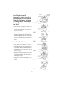
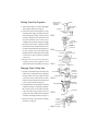
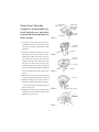
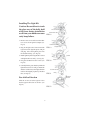
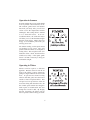
(MODEL NUMBER:AC-19052)
SAFETY PRECAUTIONS
WARNING-INSTALLATION SHOULD BE PERFORMED BY A QUALIFIED
ELECTRICAN
1. To ensure the success of the installation, be sure to read the instructions and review
the diagrams thoroughly before beginning.
2. All electrical connections must be in accordance with local codes, ordinances or
National Electrical Code. If you are unfamiliar with methods of installing
electrical wiring secure the services of a qualified electrician.
3. Make sure that your installation will not allow rotating fan blades to come in
contact with any object.
4. If you are installing more than one ceiling fan, make sure that you do not mix fan
blade sets.
5. Only mount fan to outlet box marked acceptable for ceiling fan.
6. Installation to a concrete ceiling should be performed by a qualified electrician.
7. Before beginning, disconnect power by removing fuse or turning off circuit
breaker.
8. After fan is completely installed, make sure that all connections are secured to
prevent fan from falling.
9. Do not insert anything into the fan blades while ceiling fan is operating.
10. Fan must be turned off and stopped before reversing fan direction.
11. The fan must be mounted with the blades at least 2.3m from the floor to minimum
the possibility of accidental contact with the fan blades.
12. The supply wires Live & Neutral must be connected to wall switch (double poles)
having a contact separation at least 3mm in all poles.
WARNING
WARNING
The box must be supported directly by
the building structure. The box and its
support must be able support the fan
weight - must not twist or work loose.
Do not use plastic boxes.
To reduce the risk of personal injury,
do not bend the blades when installing
the blades, balancing the blades or
cleaning the fan. Do not insert foreign
objects between rotating fan blades.
1
SCREW
Install Blade Assembly
BLADE
Caution: To reduce the risk of
personal injury. Do not bend the
blade when installing, balancing
or cleaning the fan . Do not insert
foreign objects between rotating
fan blades
FIG.1
SCREW
1. Turn the fan body upside down with
hanger bracket facing top. Place the blade
on the hanger bracket and tighten the
screws. (see Fig.1)
2. After blades are securely screwed onto
the hanger bracket side, turn the fan body
back and tighten the other side of the blade
to fan body using the screws provided. (see
Fig.2)
FIG.2
BLADE
ADAPTER
FIG.3
Installing Top Housing
TOP HOUSING
1. Undo the screws on adapter. (see Fig.3)
2. Carefully place the top housing onto the
center band. Be sure to match the hole on
top housing to the “reverse switch” on fan
body. (see Fig.4)
CENTER BAND
FIG.4
TOP HOUSING
3. Slightly turn the top housing so the holes
on top housing match the screw holes on
fan body. (see Fig.5)
4. Tighten the screws on the adapter. (see
Fig.6)
FIG.5
ADAPTER
FIG.6
2
HANGER
BRACKET
Putting Your Fan Together
HANGER BALL
DOWNROD
ASSEMBLY
1. Take off the washer, clevis pin and hairpin
clip from the downrod. (see Fig.7)
2. Insert the downrod through the center
opening in the canopy and route the motor
leads though the hanger ball/downrod
assembly. Align the clevis pin holes in the
downrod with the holes in the motor
coupling. The clevis pin must pass though
the holes in the motor coupling and the
downrod. Place the washer onto the clevis
pin and install the hairpin clip making sure
to push straight leg of the hairpin clip
through the hole near hanger ball to make
sure the clevis pin is properly installed
(see Fig.8)
3. Remove the 2 set screws in the motor
coupling and securely tighten screws
against the downrod assembly.(see Fig.9)
HAIRPIN
CLIP
WASHER
FIG.7
CLEVIS PIN
CANOPY
CANOPY HOLE
COVER
COUPLING
COVER
DOWNROD
FIG.8
COUPLING COVER
WASHER
ADAPTER
HAIRPIN CLIP
SCREW
CLEVIS PIN
FIG.9
WHITE WIRE
OUTLET BOX
Hanging Your Ceiling Fan
1. Securely attach the hanger bracket to the
outlet box by washers and screws supplied.
Connect white wire from ceiling to white
wire from receiver with wire nut. Connect
black wire from ceiling to black wire from
receiver with wire nut (see Fig.10)
2. Carefully lift the fan and seat the downrod
and ball assembly on the hanger bracket.
Be sure the groove in the ball is lined up
with tab on the hanger barcket. Do not
pinch wires between the ball and downrod
assembly and hanger barcket (see Fig.11)
3. Install the safety cable into the building
structure. (see Fig.12)
RECEIVER UNIT
FIG.10
RECEIVER UNIT
WASHER
WASHER
WASHER
SCREW
HANGER
BRACKET
DOWNROD
FIG.11
CEILING
SAFETY
CABLE
WASHER
WASHER
FIG.12 SCREW
3
HANGER
BRACKET
BLACK WIRE
HANGER
BRACKET
BLACK WIRE
WHITE WIRE
Wiring Your Ceiling Fan
Caution: To avoid possible electrical shock,be sure electricity
is turned off at the main fuse box
before wiring.
BLUE WIRE
GREEN WIRE
GREEN WIRE
FIG.13
1. If you are not sure that electrical box is
grounded,contact a licensed electrician
for advice. It must be grounded for safe
operation.
2. Connect the black wire from receiver to
the black wire from fan with wire nut.
Connect the white wire from receiver to
the white wire from fan with wire nut.
Connect the blue wire from receiver to
the blue wire from fan with wire nut.
Connect the green wire from ceiling and
green wire from hanger bracket with green
wire from hanger ball with wire nut. (see
Fig.13)
GREEN WIRE
BLACK WIRE
WHITE WIRE
BLUE WIRE
HANGER
BRACKET
SCREW
SCREW
FIG.14
HANGER
BRACKET
CANOPY
SCREW
SCREW
FIG.15
3. Remove one screw and loosen the other
screw from the hanger bracket.(see Fig.14)
4. Mount the canopy on the two screws in
the hanger bracket and twist the canopy,
so the screw heads hold the canopy in
place. (see Fig.15)
FIG.16
5. Retighten the two screws and place the
canopy hole cover and twist the cover to
tighten up. (see Fig.16)
CANOPY
CANOPY HOLE COVER
LIGHT KIT
ADAPTER
SCREW
FIG.17
4
Installing The Light Kit
Caution: Be careful not to touch
the glass area of the bulb, hold
with tissue during installation
as oil from your hands can cause
early lamp failure.
1. Remove one screw and loosen the other
two screws from light kit adapter.(see
Fig.17)
PIN AND PLUG
LIGHT KIT PLATE
FIG.18
LIGHT KIT PLATE
2. Plug in the light wires from fan and the
light wires from light kit plate with pin
and plug . Place the light kit plate into
the bottom housing. (see Fig.18)
FIG.19
SCREW
SCREW
3. Install light kit plate using the three screws
and tighten them securely. (see Fig.19)
4. Plug the G9 Bulb into the socket (see
Fig.20)
5. Carefully lift the glass shade up inside the
light fixture as far as it will go. Rotate the
shade in a clockwise (to the right) direction
until it is held tightly in place by the three
tabs (see Fig.21)
FIG.20
BULB
LIGHT KIT PLATE
GIASS
FIG.21
REVERSE
SWITCH
Fan Airflow Direction
Slide the reverse switch to right or left to
obtain opposite direction of airflow. (see
Fig.22)
FIG.22
5
Operation in Summer
In warm weather, the reverse switch should
be set to produce a downward flow of air.
The constant, gentle breeze will transfer
heat from your body; thus, you will feel
cooler even if the temperature remains
unchanged. This cooling effect is referred
to as a wind-chill factor. In an airconditioned home, the wind-chill factor
will allow you to set the thermostat higher
than the usual setting. While using less
energy to air-condition your home, you
will stay just as cool.
For summer cooling, set the speed control
on medium or fast speed. This will
provide sufficient airflow to accomplish a
cooling effect. The exception to this is in
bedrooms where a brisk, downward flow
would be too chilly. A low-speed, gentle
breeze is all that is necessary to keep you
comfortable at night.
Operating in Winter
Winter comfort requires a different
approach. Because warm air rises the air
close to the ceiling is always warmer-by
perhaps 15 degrees-than the air close to the
floor. To prevent heat from hovering
where it does little good, move the reverse
switch to create an upward airflow. This
will pull cool air up and force warm air
across the ceiling and down the walls. Set
the variable speed control fast enough to
break up the air stratification, but slow
enough not to create a draft. By keeping
the heat circulating, the heater will not
have to operate as often to keep you warm.
6
7
8