1
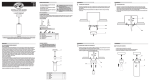
Item #xxx-xxx
Model #51536
UL Model #EF200P(A)-36
USE AND CARE GUIDE
LUXENBERG 36-INCH CEILING FAN
Questions, problems, missing parts? Before returning to the store,
call Hampton Bay Customer Service
8 a.m. - 6 p.m., EST, Monday-Friday.
1-855-HD-HAMPTON
HAMPTONBAY.COM
THANK YOU
We appreciate the trust and confidence you have placed in Hampton Bay through the purchase of this ceiling fan. We strive to continually create
quality products designed to enhance your home. Visit us online to see our full line of products available for your home improvement needs.
Thank you for choosing Hampton Bay!
Table of Contents
Table of Contents................................................................. 2
Assembly............................................................................... 7
Safety Information................................................................ 2
Operation............................................................................ 13
Warranty................................................................................ 3
Care and Cleaning.............................................................. 14
Pre-Installation..................................................................... 3
Troubleshooting.................................................................. 14
Installation............................................................................. 6
Safety Information
1. All wiring must be in accordance with the National Electrical
Code ANSI/NFPA 70 and local electrical codes. Electrical
installation should be performed by a qualified licensed
electrician.
WARNING: To reduce the risk of personal injury,
do not bend the blade brackets (also referred to as
flanges) during assembly or after installation. Do not
insert objects in the path of the blades.
2. The outlet box and support structure must be securely mounted
and capable of reliably supporting 35 lbs. (15.9 kg). Use only
UL Listed outlet boxes marked “Acceptable for Fan Support of
35 lbs. (15.9 kg) or less.”
WARNING: Remove the rubber motor stops on
the bottom of the fan before installing the blades or
testing the motor.
3. The fan must be mounted with a minimum of 7 ft (2.1 m)
clearance from the trailing edge of the blades to the floor.
WARNING: To reduce the risk of fire or electric
shock, do not use this fan with any solid-state speed
control device.
4. Do not operate the reversing switch while the fan blades are in
motion. You must turn the fan off and stop the blades before
you reverse the blade direction.
WARNING: To reduce the risk of fire, electric shock
or personal injury, mount to outlet box marked
“acceptable for fan support of 35 lbs. (15.9 kg) or
less” and use screws provided with the outlet box.
5. Do not place objects in the path of the blades.
6. Electrical diagrams are for reference only. Light kits that are not
packed with the fan must be UL listed and marked suitable for
use with the model fan you are installing. Switches must be UL
General Use Switches. Refer to the instructions packaged with
the light kits and switches for proper assembly. Use 14W CFL
bulbs max (included).
WARNING: To avoid possible electrical shock,
turn the electricity off at the main fuse box before
wiring. If you feel you do not have enough electrical
wiring knowledge or experience, contact a licensed
electrician.
7. After making electrical connections, spliced conductors should
be turned upward and pushed carefully up into the outlet box.
The wires should be spread apart with the grounded conductor
and the equipment-grounding conductor on one side of the
outlet box.
CAUTION: To reduce the risk of personal injury,
use only the screws provided with the outlet box.
CAUTION: To avoid personal injury or damage to the fan
and other items, use caution when working around or
cleaning the fan.
8. All setscrews must be checked and retightened where
necessary before installation.
2
Warranty
The supplier warrants the fan motor to be free from defects in workmanship and material present at time of shipment from the factory for a lifetime after the date of purchase by the original purchaser. The supplier also warrants that all other fan parts, excluding any glass or acrylic blades,
to be free from defects in workmanship and material at the time of shipment from the factory for a period of one year after the date of purchase
by the original purchaser. We agree to correct such defects without charge or at our option replace with a comparable or superior model if the
product is returned. To obtain warranty service, you must present a copy of the receipt as proof of purchase. All costs of removing and reinstalling
the product are your responsibility. Damage to any part such as by accident or misuse or improper installation or by affixing any accessories, is
not covered by this warranty. Because of varying climatic conditions this warranty does not cover any changes in brass finish, including rusting,
pitting, corroding, tarnishing, or peeling. Brass finishes of this type give their longest useful life when protected from varying weather conditions.
A certain amount of “wobble” is normal and should not be considered a defect. Servicing performed by unauthorized persons shall render the
warranty invalid. There is no other express warranty. Hampton Bay hereby disclaims any and all warranties, including but not limited to those
of merchantability and fitness for a particular purpose to the extent permitted by law. The duration of any implied warranty which cannot be
disclaimed is limited to the time period as specified in the express warranty. Some states do not allow a limitation on how long an implied warranty lasts, so the above limitation may not apply to you. The retailer shall not be liable for incidental, consequential, or special damages arising
out of or in connection with product use or performance except as may otherwise be accorded by law. Some states do not allow the exclusion of
incidental or consequential damages, so the above exclusion or limitation may not apply to you. This warranty gives specific legal rights, and you
may also have other rights which vary from state to state. This warranty supersedes all prior warranties. Shipping costs for any return of product
as part of a claim on the warranty must be paid by the customer.
Contact the Customer Service Team at 1-855-HD-HAMPTON or visit www.HamptonBay.com.
Pre-Installation
SPECIFICATIONS
Size
Speed
Volts
Low
36 in.
Medium
120
High
Amps
Watts
RPM
CFM
0.21
11
115
1710
0.3
23
160
2303
0.42
49
220
3204
Net
Weight
Gross
Weight
Cube Feet
14.74 lbs.
(6.7 kg)
16.28 lbs.
(7.4 kg)
1.10 cu.ft.
NOTE: These are approximate measures. They do not
include the Amps and Wattage used by the light kit.
TOOLS REQUIRED
Phillips
screwdriver
Flat blade
screwdriver
Adjustable
wrench
Electrical
tape
Wire
cutter
Step ladder
3
HAMPTONBAY.COM
Please contact 1-855-HD-HAMPTON for further assistance.
Pre-Installation (continued)
HARDWARE INCLUDED
NOTE: Hardware not shown to actual size.
AA
BB
CC
DD
EE
Part
Description
Quantity
AA
Rubber Gasket
1
BB
Pull Chain
2
CC
Plastic Wire Connector
3
Part
4
Description
Quantity
DD
Hanging Pin
1
EE
Locking Pin
1
Pre-Installation (continued)
PACKAGE CONTENTS
E
A
G
B
F
C
H
D
Part
I
Description
Quantity
A
Slide-on mounting bracket
(inside canopy)
1
B
Ball/downrod assembly
C
D
Part
Description
Quantity
E
Light kit fitter assembly
1
F
Glass shade
3
1
G
Blade
5
Canopy
1
H
Blade bracket
5
Fan-motor assembly
1
I
CFL bulb, 14-watts maximum
3
IMPORTANT: This product and/or components are
governed by one or more of the following U.S. Patents:
5,947,436; 5,988,580; 6,010,110; 6,046,416, 6,210,117
and other patents pending.
5
HAMPTONBAY.COM
Please contact 1-855-HD-HAMPTON for further assistance.
Installation
MOUNTING OPTIONS
WARNING: To reduce the risk of fire, electric shock
or personal injury, mount to outlet box marked
“Acceptable for fan support of 35 lbs. (15.9 Kg) or
less”, and use screws provided with the outlet box. An
outlet box commonly used for the support of lighting
fixtures may not be acceptable for fan support and may
need to be replaced. If in doubt, consult a qualified
electrician.
NOTE: You may need a longer downrod to maintain
proper blade clearance when installing on a steep, sloped
ceiling. The maximum angle allowable is 30° away from
horizontal.
Hanger Bar
If your ceiling fan does not have an existing UL-listed mounting
box, then install one using the following instructions:
□□ Disconnect the power by removing the fuses or turning off
the circuit breakers.
□□ Secure the outlet box directly to the building structure. Use
Outlet Box
the appropriate fasteners and materials. The outlet box and
its bracing must be able to fully support the weight of the
moving fan (at least 35 lbs.). Do not use a plastic outlet box.
The illustrations below show three different ways to mount the
outlet box.
If the canopy touches the downrod, then remove the canopy bottom
cover, and turn the canopy 180° before attaching the canopy to the
mounting plate.
To hang your fan where there is an existing fixture but no ceiling joist,
you may need an installation hanger bar as shown above
(available at any Home Depot store).
Outlet Box
Outlet Box
Provide Strong
Support
Recessed
Outlet
Box
Ceiling
Mounting
Plate
6
Assembly - Standard Ceiling Mount
1
2
Preparing for mounting
□□ Remove the mounting bracket (A) from the canopy (C) by
□□
Routing the wires
□□ Make sure the slot openings are on top, route the
wires from the fan-motor assembly (D) through the
canopy (C), and then through the ball/downrod assembly (B).
loosening the two canopy screws (FF) located in the “L
shaped” slots.
Remove and save the two canopy screws (FF) and lockwashers (GG) in the round holes. This will enable you to
remove the mounting bracket (A).
C
FF
A
B
GG
FF
C
D
3
Assembling the fan
WARNING: Failure to properly install the locking pin could
result in the fan becoming loose and possibly falling.
□□ Loosen, but do not remove, the two setscrews (HH) on the
□□
□□
□□
□□
collar (II) on top of the motor housing.
Align the holes at the bottom of the downrod (B) with the
holes in the collar (II) on top of the motor housing.
Carefully insert the hanger pin (DD) through the holes in the
collar (II) and downrod (B). Be careful not to jam the hanger
pin (DD) against the wiring inside the downrod (B).
Insert the locking pin (EE) through the hole near the end of
the hanger pin (DD) until it snaps into its locked position.
Re-tighten the two setscrews (HH) on the collar (II) on top of
the motor housing.
EE
B
DD
HH
7
II
HAMPTONBAY.COM
Please contact 1-855-HD-HAMPTON for further assistance.
Assembly - Close-To-Ceiling Mount
1
2
Close-to-Ceiling Mounting
□□ Remove the mounting bracket (A) from the canopy (C) by
□□
□□
□□ Remove three of the six screws (JJ) and lock washers (KK)
loosening the two canopy screws (FF) located in the “L
shaped” slots.
Remove and save the two canopy screws (FF) in the round
holes. This will enable you to remove the mounting bracket
(A).
Remove the canopy bottom cover (K) from the canopy (C) by
pressing the three studs.
FF
Routing the wires
□□
□□
A
□□
GG
(every other one) securing the motor collar to the top of the
fan motor housing (D).
Place the rubber gasket (AA) over the remaining three screws.
Make sure the slot opening is on top, then proceed to place
the ceiling canopy (C) over the collar at the top of the motor
(D).
Align the mounting holes with the holes in the motor (D) and
fasten, using the three screws (JJ) and lock-washers (KK)
removed previously.
Tighten the mounting screws securely.
JJ
KK
C
FF
C
AA
K
D
Assembly - Hanging the Fan
1
Attaching the fan to the electrical
box
WARNING: To reduce the risk of fire, electric shock or personal
injury, mount to outlet box marked “Acceptable for fan support
of 35 lbs. (15.9 Kg) or less”, and use screws provided with the
outlet box.
□□ Pass the 120-Volt supply wires through the center hole in the
LL
LL
mounting bracket (A).
□□ Install the ceiling mounting bracket on the outlet box by sliding
□□
the mounting bracket (A) over the two screws (LL) provided with
the outlet box. If necessary, use leveling washers (not included)
between the mounting bracket (A) and the outlet box. Note that
the flat side of the mounting bracket (A) is toward the outlet box.
When using close-to-ceiling mounting, it is important that the
mounting bracket be level.
Securely tighten the two mounting screws (LL).
A
8
Assembly - Hanging the Fan (continued)
2
3
Hanging the fan
WARNING: The hook (OO) is only to balance the fan while
making the electrical connections. Failure to hang as shown
may result in the hook (OO) breaking, causing the fan to fall.
The hook must pass from the inside to the outside of the
canopy.
WARNING: Each wire not supplied with this fan is designed to
accept up to one 12-gauge house wire and two wires from the
fan. If you have larger than 12-gauge house wiring or more
than one house wire to connect to the fan wiring, consult an
electrician for the proper size wire nuts to use.
WARNING: When hanging the fan on the hook (OO) it is
critical that you use one of the non-slotted (round) holes in
the canopy (C).
WARNING: Remove the rubber motor stops on the bottom of the
fan before installing the blades or testing the motor.
□□ Carefully lift the fan-motor assembly (D) up to the slide-on
IMPORTANT: Use the plastic wire connectors (CC) supplied with
your fan. Secure the connectors with electrical tape and ensure
there are no loose strands or connections.
mounting bracket (A).
□□ Insert the ball portion of the ball/downrod assembly into the
socket of the slide-on mounting bracket.
NOTE: The fan comes with 54 in. lead wires for use with an
extended ball/downrod assembly. If using the 4.5 in. ball/downrod
assembly (B) provided, you can cut the lead wires to your desired
length (no shorter than 12 in.).
□□ Turn the ball/downrod assembly clockwise until it is seated
□□
Making the electrical connection
with the tab of the slide-on mounting bracket aligned with the
slot in the ball.
If using close-to-ceiling mounting, hang the fan on the hook
provided by utilizing one of the round holes at the outer rim of
the ceiling canopy (C).
□□ The fan comes with 54 in. lead wires for use with an extended
Standard mount.
□□
□□
A
□□
B
□□
□□
C
ball/downrod assembly. If using the 4.5 in. ball/downrod
assembly (B) provided, you can cut the lead wires to your
desired length (no shorter than 12 in.) This will make extra
room in the canopy (C), if you do not wish to cut the wires,
you will need to neatly wrap them.
Connect the fan motor green wires to the household green or
bare wire using a wire connecting nut (CC).
Connect the fan motor white wire to the household white wire
using a wire connecting nut (CC).
Connect the fan motor black and blue wires to the household
black wire using a wire connecting nut (CC).
Secure each wire connecting nut using electrical tape.
Turn the wire connecting nut (CC) upward and push the wiring
into the outlet box (MM).
Outlet box
in the ceiling
MM
D
Black
Blue & Black White
Close to ceiling mount.
Green or Bare
Green
A
OO
C
E
9
HAMPTONBAY.COM
Please contact 1-855-HD-HAMPTON for further assistance.
Assembly - Hanging the Fan (continued)
4
5
Wrapping the extra wire
Mounting the fan-motor assembly
(standard mount)
WARNING: When using the standard ball/downrod mounting, the
tab in the ring at the bottom of the mounting bracket must rest in
the groove of the hanger ball. Failure to properly seat the tab in
the groove could cause damage to the wiring.
NOTE: Follow this step ONLY if you did not cut the extra length off
from the wires coming from the ceiling fan.
□□ Gently wrap the excess wire around the mounting bracket.
□□ Secure with electrical tape.
WARNING: The locking slots of ceiling canopy are provided only
as an aid to mounting. Do not leave the fan assembly unattended
until all four canopy screws are engaged and firmly tightened.
□□ Align the locking slots of the ceiling canopy (C) with the two
□□
□□
screws in the mounting bracket (A). Push up to engage the
slots and turn clockwise to lock in place.
Firmly tighten the two mounting screws.
Install the two mounting screws (saved from Assembly Step
1 “Prepairing for mounting”) into the holes in the canopy
(C) and tighten firmly.
A
C
D
10
Assembly - Hanging the Fan (continued)
6
Mounting the fan-motor assembly
(close-to-ceiling mount)
A
WARNING: The locking slots of ceiling canopy are provided only
as an aid to mounting. Do not leave the fan assembly unattended
until all four canopy screws are engaged and firmly tightened.
□□ Carefully unhook the fan from the mounting bracket (A) and
□□
□□
C
align the locking slots of the ceiling canopy (C) with the two
screws in the mounting bracket (A). Push up to engage the
slots and turn clockwise to lock in place. Immediately tighten
the two mounting screws firmly.
Install the two mounting screws (saved from Assembly Step
1 “Prepairing for mounting” into the holes in the canopy (C)
and tighten firmly.
You may now proceed to attaching the fan blades.
D
Assembly - Attaching the Fan Blades
1
Attaching the blade brackets
NOTE: Your fan blades are reversible. Select the blade
side finish which best accentuates you decor.
□□ Fasten the blade bracket (H) to the motor (D) by inserting
□□
the alignment post into the slot on the bottom of the fanmotor assembly (D) and tightening the motor screws that
are pre-assembled to the blade bracket (H).
Repeat for the remaining four blade brackets (H).
D
H
11
HAMPTONBAY.COM
Please contact 1-855-HD-HAMPTON for further assistance.
Assembly - Attaching the Fan Blades
2
Attaching the fan blades
NOTE: Your fan blades are reversible. Select the blade
side finish which best accentuates you decor.
□□ Mount the fan blades (G) to the blade bracket (H) by aligning
□□
□□
□□
□□
□□
the three key-slot holes in the blade (G) with the three posts
on the top of the blade brackets (H).
Hold the blade (G) close to the blade bracket (H) and press
the blade (G) down firmly. Ensure the key-slot holes are
properly seated on the blade arm posts.
While still holding the blade (G) down, firmly slide the
blade (G) away from the bracket (H) side until the blade (G)
engages in the locking mechanism (TT).
Make sure the locking mechanism (TT) at the rear of the
blade bracket (H) springs upward and butts against the edge
of the blade (G) indicating a secure connection.
Visually inspect the top of the blade bracket (H) to ensure
the locking mechanism (TT) is securely in place.
Repeat for the remaining blades (G).
D
TT
H
G
Assembly - Attaching the Light Kit
1
Attaching the light kit
WARNING: To reduce the risk of electric shock, disconnect
the electrical supply circuit to the fan before installing the
light kit.
□□ Remove the three screws (UU) from the light kit fitter
□□
□□
D
assembly (E).
Connect the wires exiting the bottom of the motor assembly
(D) by connecting the molded adaptor plugs together (blue
to black, and white to white).
Slide the light kit (E) and secure it to the switch housing
using the three screws (UU) that were removed in the first
step.
E
12
UU
Assembly - Attaching the Light Kit
2
Installing the bulbs and attaching the
glass bowl
CAUTION: Make sure the power is off before attaching or
removing the glass shade.
CAUTION: Over lamping the fan will result in the fan lights
shutting down until the proper wattage bulbs are installed.
Reset the lights by turning off the power, replacing the bulbs
with the correct wattage bulbs, and turn the power on.
D
E
VV
WARNING: Allow the glass shade to cool completely before
removing.
F
□□ Gently slide the glass shade (F) over the steel tensioners
□□
□□
(V V). Make sure the glass shade is fully inserted into the
socket for a secure fit. Repeat for the remaining glass
shades (F).
With the power off, insert and tighten the light bulbs (I) into
light kit sockets.
Attach the pull chain extensions (BB).
I
BB
Operation
Turn on the power and check the operation of the fan. The pull
chain controls the fan speeds as follows:
1 pull - High, 2 pulls - Medium, 3 pulls - Low, 4 pulls - off
A. Warm weather
The appropriate speed settings for warm or cool weather depends
on factors such as the room size, ceiling height, and number of
fans.
The slide switch controls (XX) the direction of the blades:
Forward (switch down) or Reverse (switch up).
XX
NOTE: Wait for the fan to stop before reversing the direction of
blade rotation.
A. Warm weather - (Forward) A downward airflow creates a cooling
effect. This allows you to set your air conditioner on a warmer setting
without affecting your comfort.
B. Cool weather
B. Cool weather - (Reverse) An upward airflow moves warm air off
of the ceiling. This allows you to set your heating unit on a cooler
setting without affecting your comfort.
XX
13
HAMPTONBAY.COM
Please contact 1-855-HD-HAMPTON for further assistance.
Care and Cleaning
WARNING: Make sure the power is off before cleaning
your fan.
□□ Because of the fan’s natural movement, some connections may become loose. Check the support connections, brackets, and blade
attachments twice a year. Make sure they are secure. It is not necessary to remove the fan from the ceiling.
□□ Clean your fan periodically to help maintain its new appearance over the years. Do not use water when cleaning, as this could damage
□□
□□
the motor, or the wood, or possibly cause an electrical shock. Use only a soft brush or lint-free cloth to avoid scratching the finish. The
plating is sealed with a lacquer to minimize discoloration or tarnishing.
You can apply a light coat of furniture polish to the wood for additional protection and enhanced beauty. Cover small scratches with a
light application of shoe polish.
You do not need to oil your fan. The motor has permanently-lubricated sealed ball bearings.
Troubleshooting
Problem
Solution
The fan will not start.
□□ Check the main and branch circuit fuses or breakers.
□□ Check the line wire connections to the fan and switch wire connections in the switch housing.
The fan is noisy.
□□
□□
□□
□□
□□
The fan wobbles.
□□ Check that all blade and blade arm screws are secure.
□□ Most fan wobble problems are caused when blade levels are unequal. Check this level by selecting a point on the
ceiling above the tip of one of the blades. Measure from a point on the center of each blade to the point on the
ceiling. Measure this distance. Rotate the fan until the next blade is positioned for measurement. Repeat for each
blade. Any measurement deviation should be within 1/8 in. Run the fan for ten minutes. If the fan continues to
wobble please contact Customer Service and a balancing kit will be sent to you at no charge.
Ensure all motor housing screws are snug.
Ensure the screws that attach the fan blade bracket to the motor hub are tight.
Ensure the wire nut connections are not rattling against each other or the interior wall of the switch housing.
Allow a 24-hour “breaking in” period. Most noises associated with a new fan disappear during this time.
If you are using the Ceiling Fan light kit, ensure the screws securing the glassware are tight. Check that the light
bulbs are also secure.
□□ Ensure the canopy is a short distance from the ceiling. It should not touch the ceiling.
□□ Ensure your outlet box is secure and rubber isolator pads were used between the mounting plate and outlet box.
14
Questions, problems, missing parts? Before returning to the store,
call Hampton Bay Customer Service
8 a.m. - 6 p.m., EST, Monday-Friday
1-855-HD-HAMPTON
HAMPTONBAY.COM
Retain this manual for future use.
Artículo núm. xxx-xxx
Modelo núm. 51536
Modelo aprobado por UL núm.
EF200P(A)-36
GUÍA DE USO Y MANTENIMIENTO
VENTILADOR DE TECHO LUXENBERG DE 91.4 cm
¿Preguntas, problemas o piezas faltantes? Antes de regresar a la tienda, llama
al servicio al cliente de Hampton Bay,
de lunes a viernes entre 8 a.m. y 6 p.m., (hora estándar del Este)
1-855-HD-HAMPTON
HAMPTONBAY.COM
GRACIAS POR TU COMPRA
Apreciamos la confianza que has depositado en Hampton Bay al comprar este ventilador de techo. Nos esforzamos para continuamente crear
productos de calidad diseñados para mejorar tu hogar. Visítanos por Internet para ver nuestra línea completa de productos disponibles para las necesidades de mejoras de tu hogar. ¡Gracias por elegir Hampton Bay!
Tabla de contenido
Tabla de contenido............................................................... 2
Ensamblaje............................................................................ 7
Información de seguridad................................................... 2
Funcionamiento.................................................................. 13
Garantía................................................................................. 3
Mantenimiento y limpieza.................................................. 14
Preinstalación....................................................................... 3
Solución de problemas...................................................... 14
Instalación............................................................................. 6
Información de seguridad
1. Todo el cableado debe cumplir con el Código Nacional de
Electricidad ANSI/NFPA 70 y con los códigos locales de
electricidad. La instalación eléctrica debe ser hecha por un
electricista certificado y calificado.
ADVERTENCIA: Para reducir el riesgo de lesiones
personales, no dobles los soportes de las aspas
(también llamados “bridas”) durante el ensamblaje ni
después de la instalación. No coloques objetos en la
trayectoria de las aspas.
2. La caja eléctrica y estructura de soporte deben montarse de
forma segura y tener capacidad para sostener de manera
confiable 15.9 kg. Usa solamente cajas eléctricas aprobadas
por UL marcadas como “apropiada para sostener ventiladores
de 15.9 kg o menos”.
3. El ventilador debe ir montado con un mínimo de 2.1 m de
separación entre el borde trasero de las aspas y el piso.
4. No muevas el interruptor de reversa mientras las aspas del
ventilador estén en movimiento. Debes apagar el ventilador y
esperar que se detengan las aspas antes de dar reversa a la
dirección de las aspas.
5. No coloques objetos en la trayectoria de las aspas.
6. Los diagramas eléctricos son solo para referencia. Los kits de
luces no incluidos con el ventilador deben estar aprobados
por UL y marcados como apropiados para ser usados con el
modelo de ventilador a instalar. Los interruptores deberán
estar clasificados por UL como de uso general. Consulta las
instrucciones adjuntas a los kits de luces e interruptores
para obtener información sobre el ensamblaje adecuado. Usa
bombillas CFL de un máximo de 14 W (incluidas).
7. Después de concluir las conexiones eléctricas, debes voltear
los conductores empalmados hacia arriba y meterlos con
cuidado en la caja eléctrica. Los cables deben estar separados
con el cable a tierra y el conductor a tierra del equipo hacia
uno de los lados de la caja eléctrica.
8. Todos los tornillos de fijación deben ser verificados y ajustados
donde sea necesario antes de la instalación.
ADVERTENCIA: Quita los tapones de goma del motor
que están en la parte inferior del ventilador antes de
instalar las aspas o probar el motor.
ADVERTENCIA: Para disminuir el riesgo de incendio
o descarga eléctrica, no utilices este ventilador
con ningún dispositivo de control de velocidad de
estado sólido.
ADVERTENCIA: Para reducir el riesgo de incendio,
descarga eléctrica o lesiones personales, instala solo
en una caja eléctrica clasificada como “apropiada para
sostener ventiladores de 15.9 kg o menos” y usa los
tornillos que vienen con esta..
ADVERTENCIA: Para evitar una posible descarga
eléctrica, corta la energía eléctrica en la caja principal
de fusibles antes de instalar el cableado. Si crees que
no tienes suficiente experiencia o conocimientos sobre
cableado eléctrico, contrata a un electricista certificado.
PRECAUCIÓN: Para reducir el riesgo de lesiones
personales, usa solamente los tornillos incluidos con
la caja eléctrica.
PRECAUCIÓN: Para evitar lesiones, o daños al ventilador
y otros objetos, ten cuidado al trabajar cerca del
ventilador o al limpiarlo.
2
Garantía
El proveedor garantiza de por vida, a partir de la fecha en que el comprador original lo adquiere, que el motor del ventilador no presenta defectos de
fabricación ni de materiales al momento en que es enviado desde la fábrica. El proveedor también garantiza por un período de un año, a partir de la fecha de
compra por el comprador original, que ninguna de las demás piezas del ventilador, sin incluir las aspas de vidrio o acrílico, presenta defectos de fabricación
o de material en el momento de su salida de la fábrica. Acordamos reparar todos los defectos del tipo antes mencionado sin cargo alguno o, a nuestra
discreción, reemplazar el producto por un modelo de igual calidad o superior si el producto es devuelto. Para obtener servicio de garantía, debe presentar
una copia del recibo como comprobante de compra. Todos los costos de retiro y reinstalación del producto están a su cargo. No están cubiertos bajo
esta garantía daños a ninguna de las piezas como resultado de accidentes, instalación o uso incorrectos o debido a la instalación de cualquier accesorio.
Debido a que las condiciones climáticas pueden variar, esta garantía no cubre ningún cambio en el acabado en bronce, incluyendo óxido, perforación,
corrosión, manchas o descascaramiento. Los acabados en bronce de este tipo tienen una vida útil más prolongada cuando se los protege de las condiciones
climáticas cambiantes. Es normal cierta “oscilación” y no se considerará un defecto. Cualquier servicio realizado por personal no autorizado invalidará la
garantía. No existe ninguna otra garantía expresa. Mediante la presente, Hampton Bay se exime de cualquier garantía, incluyendo, entre otras, aquellas de
comercialización e idoneidad para un fin particular, de acuerdo con lo contemplado por la ley. La duración de cualquier garantía implícita que no se pueda
eximir está limitada al período de tiempo especificado en la garantía explícita. Algunos estados no permiten una limitación en la duración de la garantía; por
consiguiente, la limitación anterior puede no aplicarse a su caso. El minorista no será responsable por daños directos, indirectos o especiales que resulten
o deriven del uso o rendimiento del producto, excepto en casos en que lo estipule la ley. Algunos estados no permiten la exclusión o limitación de daños
directos o indirectos, por lo que la limitación o exclusión anterior podría no aplicarse a su caso. Esta garantía le otorga derechos legales específicos y es
posible que también tenga otros derechos que varían de un estado a otro. Esta garantía sustituye todas las garantías anteriores. Los costos de envío de
cualquier devolución de productos hecha como parte de una reclamación de garantía están a cargo del cliente.
Comuníquese con el equipo de servicio al cliente al 1-855-HD-HAMPTON o visite www.HamptonBay.com.
Preinstalación
ESPECIFICACIONES
Tamaño
Velocidad
Voltios
Amperes
Watts
RPM
CFM
0.21
11
115
1710
0.3
23
160
2303
0.42
49
220
3204
Baja
91.4 cm
Media
120
Alta
Peso
neto
Peso
bruto
Pies
cúbicos
6.7
kg
7.4
kg
1.10 pies³
NOTA: Estas medidas son aproximadas. No incluyen ni
el amperaje ni el vataje consumido por el kit de luces.
HERRAMIENTAS NECESARIAS
Destornillador
Phillips
Destornillador
plano
Llave
ajustable
Cinta de
electricista
Cortacables
Escalera de tijera
3
HAMPTONBAY.COM
Para obtener asistencia, llama al 1-855-HD-HAMPTON.
Preinstalación (continuación)
HERRAJES INCLUIDOS
NOTA: No se muestra el tamaño real de los herrajes.
AA
BB
CC
DD
EE
Pieza
Descripción
Cantidad
AA
Junta de goma
1
BB
Cadena del interruptor
2
CC
Conector plástico para cables
3
Pieza
4
Descripción
Cantidad
DD
Pasador de soporte
1
EE
Pasador de cierre
1
Preinstalación (continu