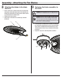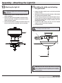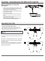
1
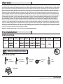
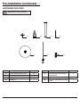
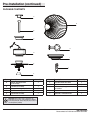
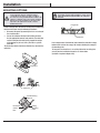
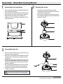
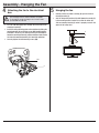
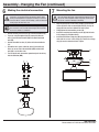
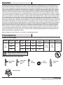
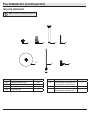
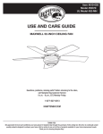
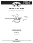
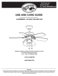
Item # 600-523, 600-524, 600-526
Model # 51327, 51328, 51329
UL Model # 48-HVA
USE AND CARE GUIDE
HAVANA 48-INCH CEILING FAN
Questions, problems, missing parts? Before returning to the store,
call Hampton Bay Customer Service
8 a.m. - 6 p.m., EST, Monday-Friday
1-877-527-0313
HAMPTONBAY.COM
THANK YOU
We appreciate the trust and confidence you have placed in Hampton Bay through the purchase of this ceiling fan. We strive to continually create
quality products designed to enhance your home. Visit us online to see our full line of products available for your home improvement needs.
Thank you for choosing Hampton Bay!
Table of Contents
Table of Contents................................................................. 2
Assembly............................................................................... 7
Safety Information................................................................ 2
Operation............................................................................ 12
Warranty................................................................................ 3
Care and Cleaning.............................................................. 13
Pre-Installation..................................................................... 3
Troubleshooting.................................................................. 13
Installation............................................................................. 6
Safety Information
1. To reduce the risk of electric shock, ensure the electricity has
been turned off at the circuit breaker or fuse box before you
begin.
WARNING: To reduce the risk of personal injury,
do not bend the blade brackets (also referred to as
flanges) during assembly or after installation. Do not
insert objects in the path of the blades.
2. All wiring must be in accordance with the National Electrical
Code ANSI/NFPA 70-1999 and local electrical codes. Electrical
installation should be performed by a qualified licensed
electrician.
WARNING: To reduce the risk of fire, electric shock
or personal injury, mount to outlet box marked
“acceptable for fan support of 35lbs. (15.9 Kg) or
less” and use screws provided with the outlet box.
3. The outlet box and support structure must be securely mounted
and capable of reliably supporting 35 lbs. (15.9 kg). Use only
UL Listed outlet boxes marked “Acceptable for Fan Support of
35 lbs. (15.9 kg) or less.”
WARNING: Remove the rubber motor stops on
the bottom of the fan before installing the blades or
testing the motor.
4. The fan must be mounted with a minimum of 7 ft (2 m) clearance
from the trailing edge of the blades to the floor.
WARNING: To reduce the risk of fire or electric
shock, do not use this fan with any solid-state speed
control device.
5. Do not operate the reversing switch while the fan blades are
in motion. You must turn the fan off and stop the blades before
you reverse the blade direction.
WARNING: To avoid possible electrical shock,
turn the electricity off at the main fuse box before
wiring. If you feel you do not have enough electrical
wiring knowledge or experience, contact a licensed
electrician.
6. Do not place objects in the path of the blades.
7. To avoid personal injury or damage to the fan and other items,
use caution when working around or cleaning the fan.
8. Electrical diagrams are for reference only. Light kits that are
not packed with the fan must be UL-listed and marked suitable
for use with the model fan you are installing. If using this fan
in a wet or damp environment, the light kit must be marked
“Suitable for Use in Wet Location”. Switches must be UL
General Use Switches. Refer to the instructions packaged with
the light kits and switches for proper assembly.
WARNING: Electrical diagrams are for reference
only. Optional use of any light kit shall be UL-listed
and marked suitable for use with this fan.
CAUTION: To reduce the risk of personal injury,
use only the screws provided with the outlet box.
9. This product is suitable for use in wet locations when installed
in a GFCI protected branch circuit.
10. All setscrews must be checked and retightened where
necessary before installation.
11. After making electrical connections, spliced conductors should
be turned upward and pushed carefully up into outlet box. The
wires should be spread apart with the grounded conductor and
the equipment-grounding conductor on one side of the outlet
box.
2
Warranty
The supplier warrants the fan motor to be free from defects in workmanship and material present at time of shipment from the factory for a lifetime after the date of purchase by the original purchaser. The supplier also warrants that all other fan parts, excluding any glass or acrylic blades,
to be free from defects in workmanship and material at the time of shipment from the factory for a period of one year after the date of purchase
by the original purchaser. We agree to correct such defects without charge or at our option replace with a comparable or superior model if the
product is returned. To obtain warranty service, you must present a copy of the receipt as proof of purchase. All costs of removing and reinstalling
the product are your responsibility. Damage to any part such as by accident or misuse or improper installation or by affixing any accessories, is
not covered by this warranty. Because of varying climatic conditions this warranty does not cover any changes in brass finish, including rusting,
pitting, corroding, tarnishing, or peeling. Brass finishes of this type give their longest useful life when protected from varying weather conditions.
A certain amount of “wobble” is normal and should not be considered a defect. Servicing performed by unauthorized persons shall render the
warranty invalid. There is no other express warranty. Hampton Bay hereby disclaims any and all warranties, including but not limited to those
of merchantability and fitness for a particular purpose to the extent permitted by law. The duration of any implied warranty which cannot be
disclaimed is limited to the time period as specified in the express warranty. Some states do not allow a limitation on how long an implied warranty lasts, so the above limitation may not apply to you. The retailer shall not be liable for incidental, consequential, or special damages arising
out of or in connection with product use or performance except as may otherwise be accorded by law. Some states do not allow the exclusion of
incidental or consequential damages, so the above exclusion or limitation may not apply to you. This warranty gives specific legal rights, and you
may also have other rights which vary from state to state. This warranty supersedes all prior warranties. Shipping costs for any return of product
as part of a claim on the warranty must be paid by the customer.
Contact the Customer Service Team at 1-877-527-0313 or visit www.HamptonBay.com.
Pre-Installation
SPECIFICATIONS
Size
Speed
Volts
Low
48”
Medium
120
High
Amps
Watts
RPM
CFM
0.24
14
60
2153
0.36
30
90
3148
0.50
60.3
130
4467
Net
Weight
Gross
Weight
Cube Feet
26.0 lbs.
(11.8 kg)
30.2 lbs.
(13.7 kg)
2.7’
NOTE: These are approximate measures. They do not
include the amps and wattage used by the light kit.
TOOLS REQUIRED
Phillips
screwdriver
Flat blade
screwdriver
Adjustable
wrench
Electrical
tape
Wire
cutter
Step ladder
3
HAMPTONBAY.COM
Please contact 1-877-527-0313 for further assistance.
Pre-Installation (continued)
HARDWARE INCLUDED
NOTE: Hardware not shown to actual size.
AA
CC
BB
EE
Part
Description
DD
GG
FF
Quantity
Part
Description
Quantity
EE
Extra plastic plug (to be used for fan
without light kit)
1
AA
Blade attachment hardware screw
16
BB
Plastic wire connector
3
CC
Hanger pin
1
FF
Pull chain
2
DD
Locking pin
1
GG
Extra screw and lockwasher for blade
bracket
1
4
Pre-Installation (continued)
PACKAGE CONTENTS
A
G
B
C
H
D
I
E
J
F
Part
A
Description
Quantity
Slide-on mounting bracket
(inside canopy)
1
B
Ball/downrod assembly
1
C
Canopy with canopy ring attached
1
D
Fan-motor assembly
E
Light kit fitter assembly
Part
Description
Quantity
F
Decorative motor collar cover
1
G
Blade
5
H
Blade bracket (flange), screws
pre-installed
5
1
I
Glass bowl
1
1
J
Light bulbs, 14-Watt maximum
3
IMPORTANT: This product and/or components are
governed by one or more of the following U.S. Patents:
5,947,436; 5,988,580; 6,010,110; 6,046,416, 6,210,117
and other patents pending.
5
HAMPTONBAY.COM
Please contact 1-877-527-0313 for further assistance.
Installation
MOUNTING OPTIONS
WARNING: To reduce the risk of fire, electric shock
or personal injury, mount to outlet box marked
“acceptable for fan support of 35lbs. (15.9 Kg) or
less” and use screws provided with the outlet box. An
outlet box commonly used for the support of lighting
fixtures may not be acceptable for fan support and
may need to be replaced. If in doubt, consult a
qualified electrician.
NOTE: You may need a longer downrod to maintain
proper blade clearance when installing on a steep, sloped
ceiling. The maximum angle allowable is 30° away from
horizontal.
Hanger Bar
If your ceiling fan does not have an existing UL-listed mounting
box, then install one using the following instructions:
□□ Disconnect the power by removing the fuses or turning off
the circuit breakers.
□□ Secure the outlet box directly to the building structure.
Outlet Box
Use the appropriate fasteners and materials. The outlet box
and its bracing must be able to fully support the weight
of the moving fan (at least 35 lbs.). Do not use a plastic
outlet box.
The illustrations below show three different ways to mount the
outlet box.
If the canopy touches the downrod, then remove the decorative canopy
bottom cover and turn the canopy 180° before attaching the canopy to
the mounting plate.
To hang your fan where there is an existing fixture but no ceiling joist,
you may need an installation hanger bar as shown above
(available at any Home Depot store).
Outlet Box
Outlet Box
Provide Strong
Support
Recessed
Outlet
Box
Ceiling
Mounting
Plate
6
Assembly - Standard Ceiling Mount
1
2
Preparation for mounting
□□ Remove the canopy ring from the canopy (C) by turning the
□□
□□
Routing the wires
□□ Route the wires exiting the top of the fan-motor
assembly (D) into the decorative motor collar cover (F)
and through the canopy ring (C).
ring to the right until it unlocks.
Remove the slide-on mounting bracket (A) from the canopy
by loosening the four screws on the top of the canopy (C).
Remove the two non-slotted screws and loosen the
slotted screws. This will enable you to remove the slide-on
mounting bracket (A).
□□ Make sure the slot openings are on top and route the
wires through the canopy (C) and then through the ball/
downrod assembly (B).
C
A
B
F
C
D
3
Assembling the fan
□□ Loosen, but do not remove, the setscrew on the collar (K) on
top of the fan-motor assembly (D).
□□ Align the holes at the bottom of the ball/downrod assembly
□□
□□
□□
(B) with the holes in the collar (K) on top of the fan-motor
assembly (D).
Carefully insert the hanger pin (CC) through the holes in the
collar (K) and ball/downrod assembly (B). Be careful not to
jam the hanger pin (CC) against the wiring inside the ball/
downrod assembly (B).
Insert the locking pin (DD) through the hole near the end of
the hanger pin (CC) until it snaps into its locked position.
Re-tighten the setscrews on the collar (K) on top of the
fan-motor assembly (D).
B
DD
CC
K
D
WARNING: Failure to properly install the locking pin could
result in the fan becoming loose and possibly falling.
7
HAMPTONBAY.COM
Please contact 1-877-527-0313 for further assistance.
Assembly - Hanging the Fan
4
5
Attaching the fan to the electrical
box
□□ Carefully lift the fan-motor assembly (D) up to the slide-on
WARNING: To reduce the risk of fire, electric shock or
personal injury, mount to outlet box marked “acceptable
for fan support of 35lbs. (15.9 Kg) or less” and use screws
provided with the outlet box.
mounting bracket (A).
□□ Seat the hanger ball portion of the ball/downrod assembly (B)
in the mounting bracket socket. Ensure that the tab on the
slide-on mounting bracket (A) socket is properly seated in the
groove in the hanger ball.
□□ Pass the 120-Volt supply wires through the center hole in the
□□
□□
Hanging the fan
mounting bracket (A).
Install the ceiling mounting plate on the outlet box by sliding the
mounting bracket (A) over the two screws (NN) provided with the
outlet box. If necessary, use leveling washers (not included) between the mounting bracket (A) and the outlet box. Note that the
flat side of the mounting bracket (A) is toward the outlet box.
Securely tighten the two mounting screws (NN).
A
B
D
NN
A
8
Assembly - Hanging the Fan (continued)
6
7
Making the electrical connection
WARNING: When using the standard ball/downrod mounting, the
tab in the ring at the bottom of the mounting bracket must rest in
the groove of the hanger ball. Failure to properly seat the tab in
the groove could cause damage to the wiring.
WARNING: Each wire nut supplied with this fan is designed to
accept up to one 12-gauge house wire and two wires from the
fan. If you have larger than 12-gauge house wiring or more than
one house wire to connect to the fan wiring, consult an electrician
for the proper size wire nuts to use.
□□ Align the locking slots of the ceiling canopy (C) with the two
IMPORTANT: Use the plastic wire connectors supplied with your
fan. Secure the connectors with electrical tape and ensure there
are no loose strands or connections.
□□
□□
□□ Connect the two green fan wires (II) to the household wire (II).
□□ If you are using the optional light kit, connect the blue fan
screws (M) in the slide-on mounting bracket (A). Push up to
engage the slots and turn clockwise to lock in place.
Firmly tighten the two mounting screws (M).
Install the remaining two mounting screws (M) into the holes
in the canopy (C) and tighten firmly.
Install the decorative canopy ring (N) by aligning the ring’s
slots with the screws in the canopy (C). Rotate the canopy
ring (N) counter-clockwise to lock in place.
A
M
LL
N
C
MM
LL
II
□□
KK
□□
□□
wire (JJ) and the black fan wire (KK) to the black household
wire (KK).
Connect the white fan wire (LL) to the white household wire
(LL).
Spread the wires apart so that the green (II) and white (LL)
wires are on one side of the outlet box (MM) and the black
wire (KK) is on the other side.
Turn the plastic wire connectors upward and push the wiring
into the outlet box (MM).
JJ
KK
□□
Mounting the fan
D
JJ
LL
KK
LL
9
HAMPTONBAY.COM
Please contact 1-877-527-0313 for further assistance.
Assembly - Attaching the Fan Blades
8
9
Attaching the blades to the blade
brackets
□□ Attach a blade (G) to a blade bracket (H) by inserting blade
□□
□□
WARNING: Remove the rubber motor stops (PP) on the bottom
of the fan before installing the blades or testing the motor.
attachment screws (AA) into the holes in the blade (G) and
through the blade bracket (H). Note that the rubber washers
are preattached to the blade bracket.
Tighten each screw securely.
Repeat these instructions for each blade (G) and blade
bracket (H).
G
Fastening the blade assemblies to
the motor
WARNING: Remove the rubber plug (QQ) on the black bracket
(RR) below the motor in order to attach the blade assembly
to the motor. Replace the rubber plug (QQ) to prevent water
from entering the switch housing and to reduce the risk of fire,
electric shock, or other personal injury.
AA
□□ Fasten the blade assembly to the fan-motor assembly (D)
□□
H
by inserting the alignment post into the slot on the bottom
of the motor and tightening the blade bracket (H) screws.
The blade bracket screws are pre-installed into the blade
bracket (H).
Repeat this step for the remaining blade assemblies.
D
PP
RR
10
QQ
H
Assembly - Attaching the Light Kit
10
11
Attaching the light kit
CAUTION: To reduce the risk of electric shock, disconnect
the electrical supply circuit to the fan before installing the
light fixture.
□□ Remove the rubber washer, hex nut, and finial from the light
□□
□□ Remove the four screws on the black bracket of the fanmotor assembly (D).
□□
□□ Connect the wires exiting the bottom of the black bracket
□□
Installing the bulbs and attaching
the glass bowl
with the light kit fitter assembly by connecting the molded
adaptor connectors together.
Secure the light kit fitter assembly to the black bracket using
the four screws that were removed in the first step above.
□□
□□
kit fitter assembly.
With power off, install the three bulbs (K) (Max. 14W, included)
by screwing into the light bulb sockets.
Position the glass bowl (I) over the threaded nipple and pass
the pull chain (FF) for the fan through the pull chain guide on
the side of the light kit fitter assembly to avoid the chain from
touching the glass bowl.
Re-install the rubber washer and hex nut to the threaded
nipple to secure the glass bowl (I) properly.
Re-install the finial.
CAUTION: Do not over tighten the hex nut, overtightening the
hex nut may cause the glass to break.
D
K
E
I
FF
NOTE: Notice the location of the fan’s slide switch. This is the switch
used to change the fan’s directional rotation. For more information
on the operation of this switch, see Operating Your Fan and Remote
Control on page 12.
11
HAMPTONBAY.COM
Please contact 1-877-527-0313 for further assistance.
Assembly - Assembling the Fan Without the Light Kit
12
Assembling the fan without the
light kit
□□ In order to use the fan without the light kit, remove the switch
□□
□□
□□
□□
□□
cup (L) from the top of the light kit fitter assembly by removing
the center hex nut inside the switch cup (L).
Thread the switch cup (L) off of the threaded nipple on the top
of the light kit fitter assembly.
Remove the four screws (OO).
Press the plastic plug (EE) into the center hole of the switch
cup (L).
Align the four screw holes in the switch cup (L) with the four
screw holes in the switch cup cover.
Position the switch cup (L) onto the black bracket and install
the screws (00) that were removed in the first step.
OO
L
EE
Operating Your Fan
The pull chain controls the fan speed as follows:
1 pull - High, 2 pulls - Medium, 3 pulls - Low, and 4 pulls - Off
Speed settings for warm or cool weather depend on factors such as
room size, ceiling height, number of fans, and so on.
NOTE: Wait for the fan to stop before reversing the direction of the blade
rotation.
The slide switch controls the direction: forward (switch left) or reverse
(switch right).
Warm weather - (Forward) A downward airflow creates a cooling effect.
This allows you to set your air conditioner on a higher setting without
affecting your comfort.
Cool weather - (Reverse) An upward airflow moves warm air off of the
ceiling. This allows you to set your heating unit on a lower setting
without affecting your comfort.
12
Care and Cleaning
WARNING: Make sure the power is off before cleaning
your fan.
□□ Because of the fan’s natural movement, some connections may become loose. Check the support connections, brackets, and blade
attachments twice a year. Make sure they are secure. It is not necessary to remove the fan from the ceiling.
□□ Clean your fan periodically to help maintain its new appearance over the years. Do not use water when cleaning, as this could damage
□□
□□
the motor, or the wood, or possibly cause an electrical shock. Use only a soft brush or lint-free cloth to avoid scratching the finish. The
plating is sealed with a lacquer to minimize discoloration or tarnishing.
You can apply a light coat of furniture polish to the wood for additional protection and enhanced beauty. Cover small scratches with a
light application of shoe polish.
You do not need to oil your fan. The motor has permanently lubricated sealed ball bearings.
Troubleshooting
Problem
Solution
The fan will not start.
□□ Check the main and branch circuit fuses or breakers.
□□ Check the line wire connections to the fan and switch wire connections in the switch housing.
The fan is noisy.
□□
□□
□□
□□
□□
The fan wobbles.
□□ Check that all blade and blade arm screws are secure.
□□ Most fan wobble problems are caused when blade levels are unequal. Check this level by selecting a point on the
ceiling above the tip of one of the blades. Measure from a point on the center of each blade to the point on the
ceiling. Measure this distance. Rotate the fan until the next blade is positioned for measurement. Repeat for each
blade. Any measurement deviation should be within 1/8 in. Run the fan for ten minutes. If the fan continues to
wobble please contact Customer Service and a balacing kit will be sent to you at no charge.
Ensure all motor housing screws are snug.
Ensure the screws that attach the fan blade bracket to the motor hub are tight.
Ensure the wire nut connections are not rattling against each other or the interior wall of the switch housing.
Allow a 24-hour “breaking in” period. Most noises associated with a new fan disappear during this time.
If you are using the Ceiling Fan light kit, ensure the screws securing the glassware are tight. Check that the light
bulbs are also secure.
□□ Ensure the canopy is a short distance from the ceiling. It should not touch the ceiling.
□□ Ensure your outlet box is secure and rubber isolator pads were used between the mounting plate and outlet box.
13
HAMPTONBAY.COM
Please contact 1-877-527-0313 for further assistance.
Questions, problems, missing parts? Before returning to the store,
call Hampton Bay Customer Service
8 a.m. - 6 p.m., EST, Monday-Friday
1-877-527-0313
HAMPTONBAY.COM
Retain this manual for future use.
Artículo Núm. 600-523, 600-524, 600-526
Modelo Núm. 51327, 51328, 51329
Modelo Núm. 48-HVA
Aprobado por UL
GUÍA DE USO Y CUIDADO DEL PRODUCTO
VENTILADOR DE TECHO HAVANA DE 1,22 METROS
¿Preguntas, problemas o piezas faltantes? Antes de volver a la tienda,
llama al Servicio al Cliente de Hampton Bay de lunes a viernes de 8 a.m. a 6 p.m.,
Hora Estándar del Este
1-877-527-0313
HAMPTONBAY.COM
GRACIAS
Apreciamos la confianza que has depositado en Hampton Bay al comprar este ventilador de techo. Nos esforzamos para continuamente crear productos de calidad diseñados para mejorar su hogar. Visítenos en Internet para ver nuestra línea completa de productos disponibles para las necesidades
de mejoras de su hogar. ¡Gracias por elegir Hampton Bay!
Índice
Índice..................................................................................... 2
Ensamblaje ........................................................................... 7
Información de Seguridad................................................... 2
Operación............................................................................ 12
Garantía................................................................................. 3
Cuidado y Mantenimiento.................................................. 13
Preinstalación....................................................................... 3
Solución de problemas...................................................... 13
Instalación............................................................................. 6
Información de Seguridad
1. Para disminuir el riesgo de descarga eléctrica, asegúrate de
que la electricidad ha sido desconectada en el cortacircuitos o
la caja de fusibles antes de comenzar la instalación.
11. Después de concluir las conexiones eléctricas, debes voltear los
conductores empalmados hacia arriba y meterlos con cuidado
en la caja eléctrica. Los cables deben estar separados, con el
cable a tierra y el conductor a tierra del equipo en uno de los
lados de la caja eléctrica.
2. Todo el cableado debe cumplir con el Código Nacional de
Electricidad ANSI/NFPA 70-1999 y con los códigos locales de
electricidad. La instalación eléctrica debe ser hecha por un
electricista certificado y calificado.
ADVERTENCIA: Para reducir el riesgo de lesiones
personales, no doblar los brazos de las aspas
(también llamados “rebordes”) durante o después
de la instalación. No insertes objetos en el trayecto
de las aspas.
3. La caja eléctrica y estructura de soporte deben montarse de
forma segura y tener capacidad para sostener de manera
confiable 35 lb. Usa solamente cajas eléctricas aprobadas por
UL marcadas como “Aprobada como soporte de ventiladores de
35 lb (15,9 kg) o menos.”
ADVERTENCIA: Para reducir el riesgo de incendio,
descarga eléctrica o lesiones personales, monta el
ventilador sobre una caja eléctrica marcada como
“aprobada como soporte de ventiladores de 35 lb
(15,9 kg) o menos”, y usa los tornillos de montaje
que vienen con la misma.
4. El ventilador debe ir montado con un mínimo de 7 pies (2 m) de
separación entre el borde trasero de las aspas y el piso.
5. No operar el interruptor de reversa mientras las aspas del
ventilador estén en movimiento. Debes apagar y detener las
aspas antes de dar reversa a la dirección de las aspas.
ADVERTENCIA: Quita los tapones de goma del
motor en la parte inferior del ventilador antes de
instalar las aspas o verificar el motor.
6. No coloques objetos en el paso de las aspas.
ADVERTENCIA: Para reducir el riesgo de incendio
o descarga eléctrica, no utilices este ventilador
con ningún dispositivo de control de velocidad de
estado sólido.
7. Para evitar lesiones, o daños al ventilador y otros objetos, ten
cuidado al trabajar cerca del ventilador o al limpiarlo.
8. Los diagramas eléctricos son sólo una referencia. Los
juegos de luces no empaquetados con el ventilador deben
estar aprobados por UL y marcados como apropiados para
ser usados con el modelo de ventilador a instalar. Si usas
este ventilador en un ambiente húmedo, el juego de luces
debe estar marcado como “Adecuado para uso en lugares
húmedos”. Los interruptores deberán estar clasicados por el
UL como de Uso General. Consulta las instrucciones adjuntas
a los juegos de luces e interruptores para obtener información
sobre el ensamblaje adecuado.
ADVERTENCIA: Para evitar una posible descarga
eléctrica, desconecta la electricidad de la caja de
fusibles principal antes de realizar el cableado.
Si crees que no tienes suficiente conocimiento o
experiencia sobre cableado eléctrico, contacta a un
electricista certificado.
9. Este producto es adecuado para uso en lugares húmedos si se
instala en un circuito derivado protegido por un interruptor con
protección de conexión a tierra (GFCI, en inglés).
CAUTION: Para reducir el riesgo de lesiones físicas,
usa sólo los tornillos provistos con la caja eléctrica.
ADVERTENCIA: Los diagramas eléctricos son
sólo una referencia. El uso opcional de cualquier
juego de luces debe estar aprobado por UL y
adecuadamente marcado para uso con este
ventilador.
10. 1Todos los tornillos colocados se deben verificar y ajustar
donde sea necesario antes de la instalación.
2
Garantía
El proveedor garantiza de por un período de 10 años, a partir de la fecha de compra por el comprador original, que el motor del ventilador no
presenta defectos de fabricación ni de material en la fecha de salida de la fábrica. El proveedor también garantiza por un período de un año, a
partir de la fecha de compra por el comprador original, que todas las demás piezas del ventilador, sin incluir ninguna aspa de vidrio o acrílico,
no presentarán ningún defecto de fabricación o de material desde el momento de su salida de la fábrica. Acordamos reparar todos los defectos
del tipo antes mencionado, sin cargo alguno, o a nuestra discreción, reemplazar el producto por un modelo de calidad comparable o superior si
el producto se devuelve. Para obtener servicio de garantía usted debe presentar una copia del recibo como comprobante de compra. Todos los
costos de retiro y reinstalación del producto son su responsabilidad. Daños a cualquiera de las piezas como resultado de accidentes, instalación
o uso incorrectos o debidos a la instalación de cualquier accesorio, no están cubiertos bajo esta garantía. Debido a que las condiciones climáticas
pueden variar, esta garantía no cubre ningún cambio en el acabado de latón, incluyendo óxido, picaduras, corrosión, manchas o descascaramiento. Los acabados de bronce de este tipo tienen una vida útil más prolongada cuando se protegen de las condiciones climáticas cambiantes. Es
normal cierta “oscilación” y no se considerará una falla. Cualquier servicio técnico conducido por personas no autorizadas anulará la garantía. No
hay ninguna otra garantía expresa. Mediante la presente Hampton Bay se exime de cualquier garantía, incluyendo pero sin limitarse a aquellas de
comercialización e idoneidad para un fin particular, de acuerdo a lo contemplado por la ley. La duración de cualquier garantía implícita que no se
pueda eximir, está limitada al período de tiempo especificado en la garantía explícita. Algunos estados no permiten limitaciones en la duración de
la garantía, por consiguiente la limitación anterior puede que no aplique en su caso en particular. El distribuidor no será responsable por daños
directos, indirectos o especiales que resulten o deriven del uso o rendimiento del producto excepto en casos en que lo estipule la ley. Algunos
estados no permiten la exclusión o limitación de daños directos o indirectos, por lo que la limitación o exclusión anterior podría no aplicarse a
su caso. Esta garantía le otorga derechos legales específicos pero es posible que también tenga otros derechos que varían de un estado a otro.
Esta garantía sustituye todas las garantías anteriores. Los costos de envío de cualquier devolución de productos hecha como parte de una reclamación de garantía deben ser pagados por el cliente.
Contacta al Equipo de Servicio al Cliente al 1-877-527-0313 o visit www.HamptonBay.com.
Preinstalación
ESPECIFICACIONES
Tamaño
Velocidad
Volts
Amperes
Watts
r/min
PIES CÚB. X
minuto
0.24
14
60
2 153
0.36
30
90
3 148
0.50
60.3
130
4 467
Baja
48”
(1.22 m)
Media
120
Alta
Peso
Neto
Peso
Bruto
Pies
Cúbicos
26.0 lb
(11.8 kg)
30.2 lb
(13.7 kg)
2.7’
NOTA: Estas medidas son aproximadas. No incluyen ni
el amperaje ni el vataje consumido por el juego de luces.
HERRAMIENTAS NECESARIAS
Destornillador
Phillips
Destornillador
para aspa
plana
Llave
ajustable
Cinta
eléctrica
Cortador de
cable
Escalera de tijera
3
HAMPTONBAY.COM
Para obtener asistencia, llama al 1-877-527-0313.
Pre-Instalación (continuación)
INCLUYE HERRAJES
NOTA: Los herrajes no se muestran en tamaño real.
AA
CC
BB
EE
Pieza
Descripción
DD
GG
FF
Cantidad
Pieza
Descripción
Cantidad
EE
Enchufe extra de plástico (para usar
en un ventilador sin juego de luces)
1
AA
Herraje de montaje de aspa
16
BB
Conector plástico de cable
3
CC
Pasador de sujeción
1
FF
Cadena del interruptor
2
DD
Pasador de cierre
1
GG
Tornillo y arandela
adicional para el soporte del aspa
1
4
Pre-Instalación (continuación)
CONTENIDOS DEL PAQUETE
A
G
B
C
H
D
I
E
J
F
Pieza
Descripción
Cantidad
Pieza
Descripción
Cantidad
A
Soporte de montaje deslizante
(dentro de la cubierta)
1
F
Cubierta decorativa del collarín
del motor
1
B
Ensamblaje de tubo bajante/bola
1
G
Aspa
5
C
Cubierta con anillo de cubierta
acoplado
1
H
Brazos del aspa (reborde), tornillos
pre-instalados
5
D
Ensamblaje del motor del ventilador
1
I
Tazón de vidrio
1
E
Ensamblaje del soporte del
juego de luces
1
J
Bombillas de luz, máximo 14-vatios
3
IMPORTANTE: Este producto y/o componentes están
gobernados por una o más de las siguientes Patentes
estadounidenses: 5,947,436; 5,988,580; 6,010,110;
6,046,416, 6,210,117 y otras patentes pendientes.
5
HAMPTONBAY.COM
Para obtener asistencia, llama al 1-877-527-0313.
Instalación
OPCIONES DE MONTAJE
ADVERTENCIA: Para reducir el riesgo de incendio,
descarga eléctrica o lesiones personales, monta el
ventilador sobre una caja eléctrica marcada como
“aprobada como soporte de ventiladores de 35 lb
(15,9 kg) o menos”, y usa los tornillos de montaje
que vienen con la caja eléctrica. Es posible que una
caja eléctrica comúnmente