1
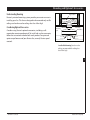
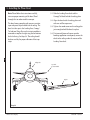
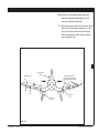
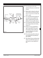
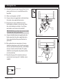
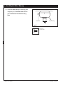
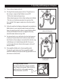
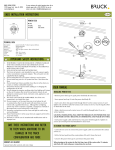
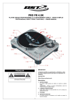
For Your Records and
Warranty Assistance
For reference, also attach your receipt or a copy
of your receipt to the manual.
__________________________________________
Model Name
__________________________________________
Model No.
__________________________________________
Date Purchased
__________________________________________
Where Purchased
Form# 42813-01
20131127
©2013 Hunter Fan Co.
Owner’s Guide and Installation Manual
Welcome
Your new Hunter® ceiling fan is an addition to your home or office that
will provide comfort and performance for many years. This installation
and operation manual gives you complete instructions for installing
and operating your fan.
We are proud of our work. We appreciate the opportunity to supply
you with the best ceiling fan available anywhere in the world.
Before installing your fan, for your records and warranty assistance,
record information from the carton and Hunter nameplate label
(located on the top of the fan motor housing).
Cautions and Warnings
2
Table of Contents
1 • Getting Ready....................................................4
2 • Installing the Ceiling Plate...........................5
3 • Installing the Plane Decal........................6-9
4 • Assembling and Hanging the Fan........ 10
5 • Wiring the Fan................................................ 11
6 • Installing the Motor Housing ................ 12
7 • Assembling the Blades............................... 13
8 • Installation of Nosecone........................... 14_
9 • Operating and Cleaning
Your Ceiling Fan............................................. 15
10 • Troubleshooting Guide........................... 16
• Read this entire manual carefully before beginning installation. Save
these instructions.
• Use only Hunter replacement parts.
• To reduce the risk of personal injury, attach the fan directly to the
support structure of the building according to these instructions,
and use only the hardware supplied.
• To avoid possible electrical shock, before installing your fan,
disconnect the power by turning off the circuit breakers to the
outlet box and associated wall switch location. If you cannot lock
the circuit breakers in the off position, securely fasten a prominent
warning device, such as a tag, to the service panel.
• All wiring must be in accordance with national and local electrical
codes and ANSI/NFPA 70. If you are unfamiliar with wiring, use a
qualified electrician.
• To reduce the risk of personal injury, do not bend the blade
attachment system when installing, balancing, or cleaning the fan.
Never insert foreign objects between rotating fan blades.
• To reduce the risk of fire, electrical shock, or motor damage, do not
use a solid-state speed control with this fan. Use only Hunter speed
controls.
© 2013 Hunter Fan Company
Hunter Fan Company
42813-01 • 11/27/13
Mounting and Optional Accessories
Understanding Mounting
Support Brace
Hunter’s patented mounting system provides you maximum ease in
installing your fan. This fan was designed to be mounted only on flat
ceilings and can be used on ceilings less than 8 feet high.
Considering Optional Accessories
Consider using Hunter’s optional accessories, including a wallmounted or remote speed control. To install and use the accessories,
follow the instructions included with each product. For quiet and
optimum performance of your Hunter fan, use only Hunter speed
controls.
Low Profile
Mounting
Style
Ceiling
Outlet Box
Low Profile Mounting fits close to the
ceiling, recommended for ceilings less
than 8 feet high
3
42813-01 • 11/27/13
Hunter Fan Company
1 • Getting Ready
To install a ceiling fan, be sure you can do the following:
•Locate the ceiling joist or other suitable support in ceiling.
•Drill holes for and install wood screws.
•Identify and connect electrical wires.
•Lift 40 pounds.
If you need help installing the fan, your Hunter fan dealer can direct
you to a licensed installer or electrician.
Gathering the Tools
4
Installing Multiple Fans?
If you are installing more than
one fan, keep the fan blades and
blade irons (if applicable) in sets,
as they were shipped.
You will need the following tools for installing the fan:
•Electric drill with 9/64” bit
•Standard screwdriver (magnetic tip recommended)
•Phillips-head screwdriver (magnetic tip recommended)
•Wrench or pliers
•Ladder (height dependent upon installation site)
•Hammer, wood block, or a rubber mallet
Checking Your Fan Parts
Carefully unpack your fan to avoid damage to the fan parts. Refer
to the included Parts Guide. Check for any shipping damage to the
motor or fan blades. If any parts are missing or damaged, contact
your Hunter dealer or call Hunter Technical Support Department at
888-830-1326.
Preparing the Fan Site
Before you begin installing the fan, follow all the instructions in
the pullout sheet called “Preparing the Fan Site.” Proper ceiling fan
location and attachment to the building structure are essential for
safety, reliable operation, maximum efficiency, and energy savings.
Hunter Fan Company
42813-01 • 11/27/13
2 • Installing of the Ceiling Plate
CAUTION: Cover plate must be securely mounted, as it
supports the entire weight of the fan.
2-1. Drill two pilot holes, 9/64" diameter in the 2 x 4 brace at the
outermost holes in the outlet box.
2-2. Install the (3) Mounting Isolators into the top of the ceiling plate.
2-3. Thread the wire leads through the center hole in the ceiling plate
and attach the ceiling plate to the brace. Use (2) #10 x 3" wood
screws and washers for mounting.
2-4. Do not tighten screws at this time. Leave a 1/2" gap between the
ceiling plate and the ceiling for insertion of the airplane decal.
2x4 Wood Brace
Outlet
Box
1/2”
Ceiling
Plate
Wood
Screws
5
Mounting
Isolator
Step 2-1
Flat Washer
Mounting Isolator
3” Wood Screw
42813-01 • 11/27/13
Hunter Fan Company
3 • Installing the Plane Decal
Note: Please follow the instructions carefully,
to insure proper mounting of the decal. Read
through first to understand the concept.
The decal comes complete with pressure sensitive
tape and special clips to hold it to the ceiling. The
decal is in four parts: the Landing Gear, Canopy/
Tail and two Wings. Be sure the insignia emblem is
mounted on top for the right wing and on bottom
for the left wing. See Step 3-4. The ceiling should
be clean and dry for proper adhesion of the tape
strips.
3-1. Slide the Landing Gear decal and the
Canopy/Tail decal behind the ceiling plate.
3-2. Align the decals with the ceiling plate and
with one wall for squareness.
3-3. Tighten the wood screws on the ceiling plate
just enough to hold the decals in place.
3-4. Put two small pieces of tape or another
bonding application to temporaly secure the
decal to the ceiling under the corners of the
Landing Gear decal.
6
Ceiling Plate
Tape with
Corners Marked
Insignia
Step 3-4
Hunter Fan Company
42813-01 • 11/27/13
Note: Make sure the double sided tape and
pressure sensative round tape is on the
non-printed side of the decal.
3-5. Mark the tape to indicate the corners of the
decal. This is extremely important as it will
give you the exact location for the decal.
Mark the positions of the wheels and the
two wing joint lines.
7
Wing Decal (2)
12”
Canopy/Tail
Decal
Mark Ceiling in These
Locations For Each Wing
(Hide Marks Under Wing)
11”
Disk
Strip
Landing Gear
Decal
Wing Joint
Line
Step 3-5
42813-01 • 11/27/13
Hunter Fan Company
3 • Installing the Plane Decal - Cont.
3-6. Loosen the wood screws and remove the
decals.
Metal
Disk
3-7. Use a wood block to drive the metal disk into
the ceiling.
Wood Block
Note: Metal Disk will leave a permanent marks in
ceiling
Hammer
3-8. Locate one metal disk between the two lines
marked for each wheel and center one metal
disk over each line marked where the wings
join the Landing gear decal.
Step 3-7
3-9. Add the strips of the pressure sensitive
rectangle tape to the back side of Canopy/
Tail decal. Locate strips then, peel off one
side of the backing and press into place.
8
3-10. Add a disk of pressure sensitive round tape
to each of the 4 metal disk that have been
driven into the ceiling. Leave the peel-off
backing on the other side of the disks and
strips until instructed to remove.
Pressure Sensitive
Round Tape
Pressure Sensitive
Round Tape
3-11. Peel the backing from the strips on the
Canopy/Tail decal and from the disks under
the wheels. Do not remove the backing from
the disks where the wings attach.
3-12. Slide the Landing Gear decal back under
the ceiling plate and align corners with lines
marked on tape. Press decal in place at
wheels.
3-13. Slide the Canopy/Tail decal under the ceiling
plate, align with the landing gear decal and
press into place on the ceiling.
Step 3-9
3-14. Tighten wood screws securely. Remove the
two pieces of tape that mark the corners.
Hunter Fan Company
42813-01 • 11/27/13
3-15. Turn each wing over and mark the
approximate dimensions on the back side of
the decal.
12”
Disk
Mark Ceiling in These
Locations For Each Wing
(Hide Marks Under Wing)
Canopy/Tail
Decal
Wing Decal (2)
3-17. Drive 2 metal disk into the ceiling for each
wing using the marks just placed in the
ceiling as a guide. Peel off one side of the
backing on the remaining disks and strips.
11”
Strip
Step 3-15
3-16. Hold each decal in place on the ceiling and
mark the ceiling at each location shown in
Step 3-15. Use the marks on the back of the
decals as a guide.
Landing Gear
Decal
Wing Joint
Line
3-18. Press the strips onto the decal and the disks
onto the clips just driven into the ceiling.
See Step 3-15.
3-19. Remove the remaining peel-off backing
from all strips and disks. Lift the corner
of the Landing Gear decal carefully and
remove the backing from the two disks
where the wings join.
3-20. Place each wing into position, making sure
you are aligned with the metal disk, and
press into place.
3-21. After the decal has been installed on ceiling,
add two strips of black decal tape over the
joint between the wing and body of the
plane.
42813-01 • 11/27/13
Hunter Fan Company
9
4 • Assembling and Hanging the Fan
4-1. Before hanging motor from ceiling plate,
install the three grommets into the holes in
the motor bracket.
Grommet
4-2. To hang the motor from the ceiling plate,
insert the “T” end of the bracket into the large
hole in the ceiling plate with the notch in it.
Insert and rotate so top of motor is towards
center of ceiling plate.
Motor
Bracket
Step 4-1
10
Ceiling
Plate
TOP
Motor
Bracket
Step 4-2
Hunter Fan Company
42813-01 • 11/27/13
5 • Wiring the Fan
5-1. Be careful when wiring so that you do not hit the
motor and let it turn, or it could fall out of the
large hole.
5-2. Make sure the power is still off.
5-3. Connect electrical supply leads to the leads from
the motor, using approved connectors.
5-4. To connect the wires, hold the bare metal
leads together and place a wire nut over them,
then twist clockwise until tight. For all these
connections use the wire nuts provided.
Motor
Bracket
CAUTION: Be sure no bare wire or wire strands
are visible after making connections.
5-5. Connect the black electrical supply lead to the
black motor lead, the white supply lead to the
white motor lead and the ground lead to the
green lead.
Step 5-4 - 5-5
11
5-6. After making the wire connections, the wires
should be spread apart, with the white and green
wires on one side of the outlet box, and the black
wires on the other side of the box. The splices
should be turned upward and pushed carefully
into the outlet box.
5-7. Complete hanging of the motor by rotating it
upwards and mounting with 3 shoulder screws
supplied.
Shoulder Screw
Step 5-6 - 5-7
Shoulder Screw
42813-01 • 11/27/13
Hunter Fan Company
6 • Installing the Motor Housing
6-1. Install the motor housing to the ceiling plate
using the (4) 8-32 machined screws that are
pre-assembled into the side of the ceiling
plate.
#8-32 Screw
Motor Housing
Step 6-1
#8-32 x 1/2”
Machine Screw
12
Hunter Fan Company
42813-01 • 11/27/13
7 • Assembling the Blades
7-1. Assemble the blades to the blade iron ring,
using the blade asembly screw.
Blade
7-2. Put the screws into the holes in the blade, set
the blade on the blade iron ring and mount
with the nuts provided. (We have provided a
wrench to tighten the nuts).
7-3. Install the blade iron ring to the motor, using
the blade Iron armature screws.
Iron Blade Ring
Step 7-1
7-4. Slide the ring with the blades attached over
the switch housing, rotating the ring until it
clears the switch housing.
7-5. Mount the ring to the motor hub with the
four screws identified above.
Blade Iron Armature Screw
13
Step 7-3
Blade
Assembly Screw
Hex Nut
Blade Iron
Armature Screw
Hex Nut
Wrench
42813-01 • 11/27/13
Hunter Fan Company
8 • Installation of Nosecone
8-1. Hand screw nosecone into bracket on bottom
of switch housing, making sure chain comes
out the bottom hole in the nosecone. Hand
tighten only.
CAUTION: Do not overtighten nosecone.
Overtighting may damage the cone.
Step 8-1
Nosecone
14
Hunter Fan Company
42813-01 • 11/27/13
9 • Operating and Cleaning your Ceiling
Fan
Step Title
9-1.Turn on electrical power to the fan.
9-2.The fan pull chain controls power to the fan. The pull chain has
four settings in sequence: High, Medium, Low and Off.
• Pull the chain slowly to change settings.
• Release slowly to prevent the chain from recoiling into the blades.
• The chain uses a breakaway connector that separates if the
chain is jerked. If this happens, simply reinsert the chain into the
connector.
9-3.Ceiling fans work best by blowing air downward (counterclockwise
blade rotation) in warm weather to cool the room with a direct
breeze. In winter, having the fan draw air upward (clockwise blade
rotation) will distribute the warmer air trapped at the ceiling
around the room without causing a draft.
In warm weather, use
downward air flow pattern
9-4.For cleaning finishes, use a soft brush or lint-free cloth to prevent
scratching. A vacuum cleaner brush nozzle can remove heavier
dust. Remove surface smudges or accumulated dirt and dust using
a mild detergent and a slightly dampened cloth. You may use
an artistic agent, but never abrasive cleaning agents as they will
damage the finish.
15
9-5.Clean wood finish blades with a furniture polishing cloth.
Occasionally, apply a light coat of furniture polish for added
protection and beauty. Clean painted and high-gloss blades in the
same manner as the fan finish.
In cold weather, use upward
air flow pattern
To Change Aireflow Direction
Turn the fan off and let it come to a complete
stop. Remove the nosecone. Slide the revering
switch on the fan to the opposite position.
Re-Install nosecone. restart fan.
Reversing
Switch
42813-01 • 11/27/13
Hunter Fan Company
10 • Troubleshooting Guide
Problem: Nothing happens; fan does not move.
1.Turn power on, replace fuse, or reset breaker.
2.Check all connections according to the wiring the fan section.
3.Push motor reversing switch firmly left or right to ensure that the
switch is engaged.
4.Pull the pull chain to ensure it is on.
Problem: Noisy operation.
1.Tighten the blade assembly screws until snug.
2.Check to see if the blade is cracked. If so, replace all the blades.
16
Problem: Excessive wobbling.
1.If your fan wobbles when operating, use the enclosed balancing kit
and instructions to balance the fan.
2.Tighten all blade iron armature screws.
3.Turn power off, support fan very carefully, and check that the
motor bracket is properly seated.
If you need parts or service assistance, please call
1-888‑830‑1326 or visit us online at
http://www.HunterFan.com.
Hunter Fan Company
7130 Goodlett Farms Pkwy, Suite 400
Memphis, Tennessee 38016
Hunter Fan Company
42813-01 • 11/27/13
11 • Notes
Step
Title
17
©2013 HUNTER FAN COMPANY
42813-01 • 11/27/13
Hunter Fan Company