Transcript
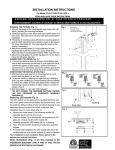
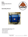
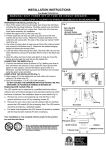
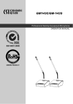
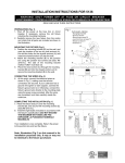
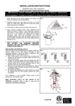
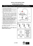
INSTALLATION INSTRUCTIONS
For Model 73106-143C-L
READ AND SAVE THESE INSTRUCTIONS
W A R N I N G ! S H U T P O W E R O F F AT F U S E O R C I R C U I T B R E A K E R .
AVERTISSEMENT! COUPER LE COURANT AU NIVEAU DES FUSIBLES OU DU DISJONCTEUR.
HANGING THE FIXTURE (Fig. 1)
Fig.1
1. Shut off the power at the circuit breaker and remove the old fixture
including the mounting hardware.
A
2. Carefully unpack your new fixture and lay out all the parts on a clear
area. Take care not to lose any small parts necessary for installation.
B
CONNECTING THE WIRES (Fig. 2)
3. While supporting the fixture, connect the electrical wires as shown in
F
Fig. 2, making sure that all wire connectors are secured. If your post
C
has a ground wire (green or bare copper), connect the fixture ground
wire to it. If not, consult your electrician for proper grounding. After
wires are connected, tuck them carefully inside the post cup (I).
4. Secure the post cup (H) to post (I) with the screws (H)
5. Bulb information: (1 x AC LED 10W included.)
D
DO NOT EXCEED THE MAXIMUM WATTAGE RATING! (NE
PAS DEPASSER LA PUISSANCE NOMINALE MAXIMALE! )
G
H
COMPLETING THE INSTALLATION (Fig. 1)
6. Remove the fixture frame (A) from the fixture body (E) by unscrewing
I
the screws(G), then attach the small glass (C) and large glass (F)
into the fixture frame (A) with clips (B).
7. Place the small round glass (D) over the LED module.
8. Re-attach fixture frame (A) to the fixture body (E) with screws (F).
Fig. 2 FIXTURE
FIXTURE
WIRES
White or
WIRES
Black or
FIXTURE
WIRES
Bare
Copper
(Ground)
Replacing LED module (Fig. 3)
The LED module can be replaced by a qualified electrician and
shut off the power at the circuit breaker and remove fixture
from the post without cutting of wire and without damage to any
decorative element to which the fixture is attached. See
installation steps for more details (Fig 3.)
HOUS
E
WIRES
Black
(Hot)
HOUS
E
WIRES
White
(Neutra
HOUS
E
WIRES
Green
or
Fig.3
D
1. Remove the fixture frame (A) by loosening screws (F).Fig.1 Remove
I
J
the small round glass (D)
2. Disconnect the fixture wires and the supply wires, then unscrew the
screw (Q)
3. Remove screws (I) to disassemble the module cover (J), glass
(K), module ring (L), LED module (M) and the metal support
(O).
4. Carefully remove the LED module for re-lamping. Note: The
LED module should be provided by a specified supplier.
5. For better heat dissipation the LED module should be installed
with the heat transfer material (N) when re-lamping
Your installation is now complete. Return power to the
junction box and test the fixture
K
M
P
L
N
O
Q