Transcript
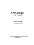
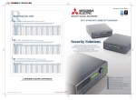
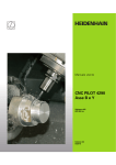
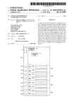
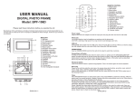
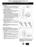
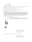
INSTALLATION INSTRUCTIONS FOR 374-267-L
For Wall Mount Fixture
W A R N I N G ! S H U T P O W E R O F F AT F U S E O R C I R C U I T B R E A K E R .
AV E R T I S S E M E N T ! C O U P E R L E C O U R A N T A U N I V E A U D E S F U S I B L E S O U D O D I S J O N C T E U R .
PREPARATION
1. Shut off power at the fuse box or circuit breaker box. If
necessary remove the old fixture and mounting hardware.
2. Carefully unpack your new fixture and lay out all the parts
on a clear area. Take care not to lose any small parts
necessary for installation.
FIG.1
Set A# A-021-106D
Back plate
Green screw
Mounting Screws(2)
MOUNTING THE FIXTURE (FIG. 1)
Secure mounting back plate (B) to junction box (A) using
junction boxes screws (C) (Size: 8-32*1/2”L). The side of the
mounting back plate marked “GND” must face out.
CONNECTING THE WIRES (FIG. 2)
3. At this point, connect the electrical wires as shown in Fig.
2, making sure that all wire connectors (F) are secured. If
your outlet has a ground wire (E) (green or bare copper),
connect the fixtures ground wire to it. Otherwise, connect
the fixture ground wire directly to the mounting plate (B)
using the green screw provided. After wires are
connected, tuck them carefully inside the junction box.
4. Align the fixture’s back plate (L) over the mounting back
plate (B) and secure with screws (D).
FINISHING THE INSTALLATION (FIG.1)
5. Align the decorative holder (H) over the fixture back
plate (L) and secure with screws (G).
6. Carefully slide glass shade G374 (K) into the front bracket
(M) and secure the glass holder (J) to the front bracket
with screws (I).
Fig.2
FIXTURE
WIRES
Black or
Smooth
FIXTURE
WIRES
White or
Ribbed
FIXTURE
WIRES
Bare
Copper
(Ground)
CAUTION /ATTENTION: When handling the fixture, do not
apply pressure to the LEDs. Hold the fixture by the back plate
(L) or front bracket (M).
HOUSE
WIRES
Black
(Hot)
Replacing LED module (Fig. 3)
The LED module can be replaced by a qualified electrician
without cutting of wire and without damage to any decorative
element to which the fixture is attached. See installation steps
for more details (Fig 3.)
a. Shut off power. Remove screws (I) glass holder (J) and
glass shade G374 (K) as well as screws (G) and
decorative holder (H).
b. Remove the wire nuts located inside the fixture back plate
to disconnect the LED module.
c. Remove cover (N) on LED module (P) and screws (O) on
bracket (M). Carefully remove the LED module (P) from
bracket (M).
d. Reverse steps a-c for installing the new LED module.
e. Note: The LED module should be provided by a specified
supplier.
f. For better heat dissipation the LED module (P) should be
applied with thermal grease when re-lamping.
HOUSE
WIRES
White
(Neutral)
HOUSE
WIRES
Green or
Bare
Copper(G
round)
Fig 3
IMPORTANT: Fixture should be installed by a qualified
electrician to ensure proper wiring and installation.
Dimmable with ELV and/or LED compatible wall
dimmer switches.