1
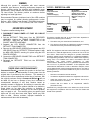
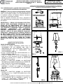
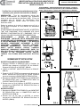
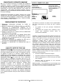
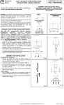
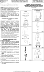
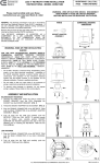
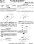
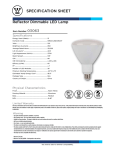
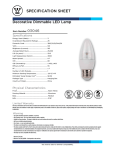
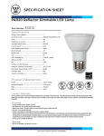
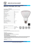
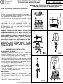
LED 4” RETROFIT TRIM INSTALLATION INSTRUCTIONS - MODEL CER4742 Please read carefully and save these instructions, as you may need them at a later date. QUESTIONS? CALL TOLL FREE 1-800-345-0542 WARNING - RISK OF ELECTRIC SHOCK. DISCONNECT MAIN POWER AT FUSE OR CIRCUIT BREAKER BEFORE INSTALLING OR SERVICING THE FIXTURE. HOUSING DIMENSIONS SOCKET ADAPTER ASSEMBLY 5 ½ in. GENERAL: All electrical connections must be in accordance with local and National Electrical Code (N.E.C.) standards. If you are unfamiliar with proper electrical wiring connections obtain the services of a qualified electrician. PARTS Remove the trim from the box and make sure that no parts are missing by referencing the PARTS illustrations. THIS RETROFIT ASSEMBLY IS ACCEPTED AS A COMPONENT OF A LED LUMINAIRE WHERE THE SUITABILITY OF THE COMBINATION SHALL BE DETERMINED BY CSA OR CANADIAN AUTHORITIES HAVING JURISDICTION. 4 in. RETROFIT TRIM WARNING – RISK OF ELECTRIC SHOCK. INSTALL THIS TRIM IN RECESSED HOUSINGS THAT HAVE DIMENSIONS SHOWN IN FIG. 1, WHICH INCLUDE THE FOLLOWING LUMINAIRES: COMMERCIAL ELECTRIC MODELS HBR2000R, HBR2000B, HBR2000BICAT; HALO MODELS H99T, H99RT, H99ICT, H99TAT, H99RTAT, H99ICAT; CORDELIA MODLES X2000LICAT, X2000LRICAT, X2000LICATB; CAPRI MODELS R4, RR4; ELCO MODELS EL99A, EL99RA, EL99ICA; JUNO MODELS TC1, TC1R; LITHONIA MODELS L3, L3R; PROGRESS MODELS P832-TG, P830-TG; THOMAS MODEL; PS4, PS4-RM; NORA MODEL NSCIC-40IAT; ELITE MODELS B4, 4R. _______________________________ FIG. 1 ASSEMBLY AND INSTALLATION INCANDESCENT HOUSINGS 1.Unscrew the WING NUT inside the CAN to detach the SOCKET BRACKET from the CAN. Disengage the SOCKET from the SOCKET BRACKET. (FIG. 2) 2.Thread the SOCKET ADAPTER into the SOCKET. (FIG. 3) 3.Attach the GROUND WIRE to the CAN using the provided self-tapping GROUND SCREW and star washer. Make sure that the GROUND SCREW does not interfere with the entry of the RETROFIT TRIM into the HOUSING. 4.Plug the FEMALE CONNECTOR of the RETROFIT TRIM onto the MALE CONNECTOR of the SOCKET ADAPTER ASSEMBLY. (FIG. 4) 5.Tuck all wires into the CAN and carefully push the RETROFIT TRIM into CAN. (FIG. 5) FIG. 2 LED HOUSINGS 1.Plug the FEMALE CONNECTOR of the RETROFIT TRIM onto the MALE CONNECTOR of the HALO HOUSING. (FIG. 4) 2.Tuck all wires into the CAN and carefully push the RETROFIT TRIM into CAN. (FIG. 5) FIG. 4 ALL RIGHTS RESERVED. COPYRIGHT COMMERCIAL ELECTRIC 2013 FIG. 3 FIG. 5 _______ DIMMING Although this product is compatible with most common residential type dimmers, dimming performance depends on dimmer, dimmer setting (for dimmers with brightness range adjustments), wiring method, and the number of LED modules. For best results, set dimmer position at maximum before adjusting to a lower light level. Recommended Dimmers (minimum load of four LED modules may be required for optimal dimming performance): Leviton Decora – 6631, IPI06, Lutron Skylark – S-603PGH, and Lutron Diva – DVWCL-153PDH, CTCL-153PDH, and TGCL-153PH. ____________________ DRIVER REPLACEMENT To replace a malfunctioning driver: 1. DISCONNECT MAIN POWER AT FUSE OR CIRCUIT BREAKER. 2. Pull the RETROFIT TRIM down from the RECESSED HOUSING. Unplug the FEMALE CONNECTOR of the RETROFIT TRIM from the MALE CONNECTOR of the SOCKET ADAPTER ASSEMBLY. 3. Separate the LED DRIVER CONNECTOR from the RETROFIT TRIM CONNECTOR. 4. Remove the LED DRIVER SCREWS and separate the OLD LED DRIVER from the RETROFIT TRIM and replace it with the NEW LED DRIVER, securing it in place using the LED DRIVER SCREWS. 5. Connect the LED DRIVER CONNECTOR to the RETROFIT TRIM CONNECTOR. 6. Re-install the RETROFIT TRIM into the RECESSED HOUSING. _____________________________ THREE-YEAR LIMITED WARRANTY Commercial Electric warrants this product to be free from defects in material and workmanship for three years from the original date of purchase by the consumer. This warranty is limited to the counter replacement at the time of purchase, with the original purchase receipt. Commercial Electric will not be liable for the loss or damage of any kind, incidental or consequential damages of any kind, whether based on warranty contract or negligence, and arising in connection with the sale, use or repair of the product claimed to be defective. Some states do not allow the exclusion or limitation of incidental or consequential damages so the above limitation may not apply to you. This warranty gives you specific legal rights and you may also have other rights, which vary from state to state. Misuse, accident, improper installation or maintenance will also void the warranty. MODEL: RHPS311AL-JW0 Max Case Temperature 90°C Dimmable LPS Power Supply AC INPUT: 120 Vac/ 200mA 60 Hz AC INPUT L-BLACK N-WHITE •tc DC OUTPUT: Regulated current 350 mA Voltage range 18-32V Maximum power 11.2 W Maximum voltage 37 V + RED - BLACK CDL Made in China This device complies with part 15 of the FCC Rules. Operation is subject to the following two conditions: 1. This device may not cause harmful interference, and 2. This device must accept any interference received, including interference that may cause undesired operation. NOTE: This equipment has been tested and found to comply with the limits for a Class B digital device, pursuant to Part 15 of the FCC Rules. These limits are designed to provide reasonable protection against harmful interference in a residential installation. This equipment generates, uses and can radiate radio frequency energy and, if not installed and used in accordance with the instructions, may cause harmful interference to radio communications. However, there is no guarantee that interference will not occur in a particular installation. If this equipment does cause harmful interference to radio or television reception, which can be determined by turning the equipment off and on, the user is encouraged to try to correct the interference by one or more of the following measures: • Reorient or relocate the receiver antenna. • Increase the separation between the equipment and receiver. • Install the product onto on a circuit different from that to which the receiver is connected. • Consult with the dealer or an experienced radio/TV technician for help. CAUTION: Any changes made to the electronics circuit will void this equipment’s compliance with Part 15 of the FCC Rules and should not be operated. ALL RIGHTS RESERVED. COPYRIGHT COMMERCIAL ELECTRIC 2013 INSTRUCCIONES PARA LA INSTALACIÓN DEL ADAPTADOR DECORATIVO LED DE 4” – MODELO CER4742 Lea cuidadosamente y guarde estas instrucciones ya que podría necesitarlas más adelante. ¿PREGUNTAS? LLAME GRATIS AL 1-800-345-0542 ADVERTENCIA: RIESGO DE DESCARGA ELÉCTRICA. DESCONECTE EL SUMINISTRO ELÉCTRICO DE LA CAJA DE FUSIBLES O LOS INTERRUPTORES DE CIRCUITO ANTES DE INSTALAR O DAR MANTENIMIENTO A LA UNIDAD. GENERAL: Todas las conexiones eléctricas deben realizarse conforme a las normas locales y al Código Eléctrico Nacional (N.E.C. por sus siglas en inglés). Si no está familiarizado con la instalación correcta de cableado eléctrico, contrate los servicios de un electricista certificado. PARTES DIMENSIONES DE LA CAJA UNIDAD DEL ADAPTADOR DEL PORTALÁMPARAS 5 ½ in. Retire el adaptador decorativo de la caja y asegúrese de tener todas las piezas comparándolas con las ilustraciones de las PARTES. ADVERTENCIA – RIESGO DE DESCARGA ELÉCTRICA. INSTALE ESTE ADAPTADOR DECORATIVO EN LAS CAJAS DE LUZ EMPOTRADAS QUE TIENEN LAS DIMENSIONES INDICADAS EN LA FIG. 1, INCLUYENDO LAS SIGUIENTES LUMINARIAS: MODELOS HBR2000R, HBR2000B, HBR2000BICAT DE COMMERCIAL ELECTRIC; MODELOS H99T, H99RT, H99ICT, H99TAT, H99RTAT, H99ICAT DE HALO; MODELOS X2000LICAT, X2000LRICAT, X2000LICATB DE CORDELIA; MODELOS R4, RR4 DE CAPRI; MODELOS EL99A, EL99RA, EL99ICA DE ELCO; MODELOS TC1, TC1R DE JUNO; MODELOS L3, L3R DE LITHONIA; MODELOS P832-TG, P830-TG DE PROGRESS; MODELOS PS4, PS4-RM DE THOMAS; MODELO NSIC-40IAT DE NORA; MODELOS B4, 4R DE ELITE. 4 in. ADAPTADOR DECORATIVO FIG. 1 ______________________ MONTAJE E INSTALACIÓN CAJAS INCANDESCENTES 1.Remueva la TUERCA MARIPOSA ubicada dentro del ALOJAMIENTO DE LA LÁMPARA para soltar la ABRAZADERA DEL PORTALÁMPARAS. Desconecte el PORTALÁMPARAS de la ABRAZADERA DEL PORTALÁMPARAS. (FIG. 2) 2.Inserte el ADAPTADOR DEL PORTALÁMPARAS en el PORTALÁMPARAS. (FIG. 3) 3.Taladre el TORNILLO DE TIERRA autoperforante en el techo de la CAJA. Asegúrese de que el TORNILLO DE TIERRA no interfiere con la entrada del ADAPTADOR DECORATIVO en la CAJA. 4.Enchufe el CONECTOR HEMBRA del ADAPTADOR DECORATIVO al CONECTOR MACHO de la UNIDAD DEL ADAPTADOR DEL PORTALÁMPARAS (FIG. 4) 5.Coloque todos los cables en el ALOJAMIENTO DE LA LÁMPARA y presione con cuidado el ADAPTADOR DECORATIVO en el ALOJAMIENTO DE LA LÁMPARA. (FIG. 5) CAJAS LED 1.Enchufe el CONECTOR HEMBRA del ADAPTADOR DECORATIVO en el CONECTOR MACHO de la CAJA HALO. (FIG. 4) 2.Coloque todos los cables en el Coloque todos los cables en el ALOJAMIENTO DE LA LÁMPARA y presione con cuidado el ADAPTADOR DECORATIVO en el ALOJAMIENTO DE LA LÁMPARA. (FIG. 5) FIG. 3 FIG. 2 FIG. 4 TODOS LOS DERECHOS RESERVADOS. PROPIEDAD INTELECTUAL COMMERCIAL ELECTRIC 2013 FIG. 5 ____________________________________ REGULADOR DE INTENSIDAD DE LA LUZ MODELO: RHPS311AL-JW0 Aunque este producto es compatible con la mayoría de los reguladores (“dimmers”) residenciales más comunes, su rendimiento depende del regulador, ajuste del regulador (en modelos con ajustes para escala de luminosidad), método de cableado y número de módulos LED. Para mejores resultados, coloque el regulador en la posición máxima antes de ajustarlo a un nivel de luz más bajo. Temperatura Máxima de la Caja 90°C Luz Regulable •tc Fuente de Alimentación LPS Reguladores recomendados (podría ser necesaria una carga mínima para cuatro módulos LED para un rendimiento óptimo): Leviton Decora – 6631, IPI06, Lutron Skylark – S-603PGH, and Lutron Diva – DVWCL-153PDH , CTCL-153PDH, y TGCL153PH. ENTRADA DE AC: 120 Vac/200mA 50/60 Hz ENTRADA DE AC L-NEGRO N-BLANCO _____________________________ REEMPLAZO DE CONTROLADOR 1. Desconecte la alimentación principal de en el fusible o disyuntor. 2. Baje el adaptador decorativo desde la caja empotrada. Desenchufe el conector hembra (de la caja empotrada) y el conector macho (del conjunto del adaptador de enchufe). 3. Separe el conector controlador de LED del conector del adaptador decorativo. 4. Quite los tornillos del controlador de LED y separar el antiguo controlador de LED del adaptador decorativo y reemplázalo con el nuevo controlador de LED, manteniéndolo en su lugar con los tornillos del controlado de LED. 5. Enchufe el conector controlador de LED con el conector del adaptador decorativo. 6. Vuelva a instalar el adaptador decorativo en la caja empotrada. __________________________________ GARANTÍA LIMITADA POR TRES AÑOS Commercial Electric garantiza este producto contra defectos en sus materiales y mano de obra por un plazo de tres años a partir de la fecha de compra. Esta garantía está limitada al cambio del producto en el mostrador al momento de la compra, con la presentación del recibo de compra original. Commercial Electric no se responsabiliza por ningún tipo de pérdida o daño así como tampoco por daños incidentales o indirectos, ya sea que se basen en el contrato de garantía o en negligencia y que resulten de la venta, uso o reparación del producto que se reclama como defectuoso. Algunos estados no permiten la exclusión o limitación de daños incidentales o indirectos por lo cual la limitación anterior podría no aplicar a su caso. Esta garantía le otorga derechos legales específicos y usted podría tener otros derechos que varían según el estado. El uso indebido, accidente, instalación o mantenimiento incorrectos invalidarán también la garantía SALIDA DE DC: Corriente regulado 350 mA Intervalo de voltaje 18-32V Potencia máxima 11.2 W Voltaje máximo 37 V + ROJO - NEGRO CDL Hecho en China Este aparato cumple con la parte 15 de las normas FCC. La operación está sujeta a las siguientes dos condiciones: 1. Este dispositivo no puede causar interferencia dañina, y 2. Este dispositivo debe aceptar cualquier interferencia recibida, incluidas las interferencias que puedan provocar un funcionamiento no deseado. NOTA: Este equipo ha sido probado y se ha encontrado que cumple con los límites para un dispositivo digital de la Clase B de conformidad con la Parte 15 de las Reglas de la FCC. Estos límites están diseñados para proveer protección razonable contra interferencia dañina en una instalación residencial. Este equipo genera, usa y puede emitir energía de frecuencia de radio y, si no es instalado y usado de acuerdo con las instrucciones, puede causar interferencia dañina a las comunicaciones de radio. Sin embargo, no existe garantía de que no ocurrirá interferencia en una instalación en particular. Si este equipo causa interferencia dañina a la recepción de radio o televisión, la cual se puede determinar al apagar y encender el equipo, pedimos al usuario que intente corregir la interferencia por medio de una o más de las siguientes medidas: • Reorientar o reubicar la antena receptora. • Incrementar la separación entre el equipo y el receptor. • Conectar el equipo a un enchufe que se encuentre dentro de un circuito diferente a donde está conectado el receptor. • Consultar a su distribuidor o un técnico de radio/TV especializado para obtener ayuda. PRECAUCIÓN: Cualquier cambio hecho al circuito electrónico anulará el cumplimiento de este equipo con la Parte 15 de las Reglas de la FCC y no debe ser operado. TODOS LOS DERECHOS RESERVADOS. PROPIEDAD INTELECTUAL COMMERCIAL ELECTRIC 2013 MODE D’INSTALLATION POUR GARNITURE DE RÉNOVATION AVEC MODULE DEL DE 10,16 CM MODÈLE CER4742 Veuillez lire ces instructions attentivement et les conserver pour pouvoir les consulter au besoin. DES QUESTIONS? APPELEZ SANS FRAIS AU 1-800-345-0542 AVERTISSEMENT – RISQUE DE DÉCHARGE ÉLECTRIQUE. COUPEZ LE COURANT AU NIVEAU DU DISJONCTEUR OU DE LA BOÎTE DE FUSIBLES AVANT D’INSTALLER OU D’EFFECTUER L’ENTRETIEN DU LUMINAIRE. DIMENSIONS DU BOÎTIER SUPPORT ADAPTATEUR 13,97 cm GÉNÉRALITÉS : Tous les raccordements doivent être effectués conformément aux exigences des règlements locaux et du code national de l’électricité (CNE). Si vous ne connaissez pas les principes de raccordement d’une installation électrique, veuillez utiliser les services d’un électricien certifié. PIÈCES Retirez la garniture de la boîte et assurez-vous qu’il n’y a aucune pièce manquante en vous référant aux illustrations des PIÈCES. LE NÉCESSAIRE DE MODERNISATION EST ACCEPTÉ EN TANT QUE COMPOSANT D’UN LUMINAIRE LED, SOUS RÉSERVE D’APPROBATION DE L’ENSEMBLE PAR LA CSA OU PAR LES POUVOIRS DE RÉGLEMENTATION. AVERTISSEMENT – RISQUE DE DÉCHARGE ÉLECTRIQUE. INSTALLEZ CETTE GARNITURE DANS UN BOÎTIER DONT LES DIMENSIONS CORRESPONDENT À CELLES INDIQUÉES À LA FIGURE 1. LES MODÈLES SUIVANTS CONVIENNENT NOTAMMENT À CETTE GARNITURE: COMMERCIAL ELECTRIC HBR2000R, HBR2000B, HBR2000BICAT; HALO H99T, H99RT, H99ICT, H99TAT, H99RTAT, H99ICAT; CORDELIA X2000LICAT, X2000LRICAT, X2000LICATB; CAPRI R4, RR4; ELCO EL99A, EL99RA, EL99ICA; JUNO TC1, TC1R; LITHONIA L3 L3R; PROGRESS P832-TG, P830-TG; THOMAS PS4, PS4-RM; NORA NSIC-40IAT; ELITE B4, 4R. GARNITURE DE RÉNOVATION 10,16 cm FIG. 1 ______________________________ ASSEMBLAGE ET INSTALLATION NICHES POUR LAMPE À INCANDESCENCE 1. Dévissez l’ÉCROU À OREILLES situé à l’intérieur du BOÎTIER pour détacher le SUPPORT DE LA DOUILLE. Dégagez la DOUILLE du SUPPORT. (FIG. 2) 2. Vissez le SUPPORT ADAPTATEUR dans la DOUILLE. (FIG. 3) FIG. 3 FIG. 2 3. Percer la VIS DE TERRE auto-perceur sur le dessus de la BOÎTE. Assurez-vous que la VIS DE TERRE n'interfère pas avec l'entrée de la GARNITURE DE RÉNOVATION. 4. Branchez le CONNECTEUR FEMELLE de la GARNITURE DE RÉNOVATION dans le CONNECTEUR MÂLE du SUPPORT ADAPTATEUR. (FIG. 4) 5. Rentrez tous les fils à l’intérieur du BOÎTIER et poussez doucement la GARNITURE DE RÉNOVATION dans le BOÎTIER. (FIG. 5) NICHES POUR DEL 1. Branchez le CONNECTEUR FEMELLE de la GARNITURE DE RÉNOVATION dans le CONNECTEUR MÂLE du BOÎTIER HALO. (FIG. 4) 2. Rentrez tous les fils dans le BOÎTIER et poussez doucement la GARNITURE DE RÉNOVATION dans le BOÎTIER. (FIG. 5) FIG. 4 TOUS DROITS RÉSERVÉS COMMERCIAL ELECTRIC 2013 FIG. 5 _____________________________________ GRADATION DE L’INTENSITÉ LUMINEUSE Bien que ce produit convienne à la plupart des gradateurs résidentiels courants, la gradation de l’intensité lumineuse dépend du gradateur lui-même, de ses réglages (dans le cas de gradateurs comportant une programmation des intensités lumineuses), du type de filage électrique et du nombre de modules DEL. Pour obtenir de meilleurs résultats, ouvrez le gradateur à la plus forte intensité lumineuse avant de diminuer le niveau d’éclairage. Gradateurs recommandés (la charge minimale pour quatre modules DEL peut être nécessaire pour assurer un meilleur contrôle du niveau d’éclairage) : Leviton Decora – 6631, IPI06, Lutron Skylark – S-603PGH et Lutron Diva – DVWCL-153PDH, CTCL-153PDH, et TGCL-153PH. ________________________________ REMPLACEMENT DE CONTRÔLEUR 1. Débranchez l'alimentation principale du fusible ou disjoncteur. 2. Bassier le GARNITURE DE RÉNOVATION de la BOÎTIER. Débranchez le CONNECTEUR FEMELLE de la GARNITURE DE RÉNOVATION du CONNECTEUR MÂLE du SUPPORT ADAPTATEUR. 3. Séparer le connecteur de contrôleur LED du GARNITURE DE RÉNOVATION connecteur. 4. Retirez les vis du pilote LED et de séparer l'ancien pilote LED de la GARNITURE DE RÉNOVATION et de le remplacer avec le nouveau pilote de LED, il la fixer en place à l'aide des vis pilote LED. 5. Branchez le connecteur du contrôleur de LED avec le connecteur de la GARNITURE DE RÉNOVATION. 6. Réinstaller le GARNITURE DE RÉNOVATION dans le BOÎTIER. _________________________________ GARANTIE LIMITÉE DE TROIS ANS Commercial Electric garantit ce produit contre tout défaut de matériaux ou de fabrication pour une période d’trois ans à partir de la date d’achat initial par le client, à l’exception de la pile. La garantie se limite à la correction desdits défauts en remplaçant le produit défectueux, accompagné de la preuve d’achat originale. Cette garantie ne couvre pas les ampoules. Commercial Electric ne pourra être tenue responsable d’aucune perte ou dommage de quelque sorte que ce soit, d’aucun dommage accessoire ou indirect, fondé sur la garantie ou la négligence, découlant de la vente, de l’utilisation ou de la réparation du produit réputé défectueux. Certains États interdisent l’exclusion ou la limitation des dommages accessoires ou indirects et, par conséquent, cette garantie peut ne pas s’appliquer à vous. Cette garantie vous confère des droits spécifiques, en sus des autres droits dont vous pourriez bénéficier et qui peuvent varier d’un État à l’autre. Une utilisation incorrecte, un accident, une installation inadéquate ou un entretien déficient aura pour effet d’annuler la présente garantie. MODÈLE: RHPS311CL-JW0 SORTIE CC: Courant régulé 350mA Intervalle de tension 18-32V Puissance maximale 11.2 W Tension maximale 37 V + ROUGE - NOIR Température Max. du Boîtier 90°C Lumière Réglable Source de Courant LPS ENTRÉE AC: 120 Vac/200 mA 60 Hz ENTRÉE AC L-NOIR N-BLANC CDL Made in China Cet appareil est conforme à la partie 15 de la réglementation FCC. Son fonctionnement est soumis aux deux conditions suivantes: 1. Cet appareil ne doit pas provoquer d'interférences nuisibles, et 2. Cet appareil doit accepter toute interférence reçue, incluant toute interférence pouvant causer un fonctionnement indésirable. À NOTER : Cet équipement a été testé et déclaré conforme aux limites des appareils numériques de classe B, aux termes de l'article 15 des règles de la FCC. Ces limites sont conçues de manière à fournir une protection raisonnable contre les interférences nuisibles dans le cadre d'une installation résidentielle. Cet appareil produit, utilise et peut émettre des hyperfréquences qui, si l'appareil n'est pas installé et utilisé selon les consignes données, peuvent causer des interférences nuisibles aux communications radio. Cependant, rien ne peut garantir l'absence d'interférences dans le cadre d'une installation particulière. Si cet appareil est la cause d'interférences nuisibles pour la réception des signaux de radio ou de télévision, ce qui peut être décelé en fermant l'équipement, puis en le remettant en fonction, l'utilisateur pourrait essayer de corriger la situation en prenant les mesures suivantes: réorienter ou déplacer l'antenne de réception; augmenter la distance entre l'équipement et le récepteur; brancher l'équipement sur un autre circuit que celui utilisé par le récepteur; demander l'aide du marchand chevronné en radio/télévision. ou d'un technicien MISE EN GARDE : Toute modification du circuit électrique aura pour effet d'annuler la conformité de l'appareil aux exigences du FCC, partie 15, et, par conséquent, devrait être évitée. TOUS DROITS RÉSERVÉS COMMERCIAL ELECTRIC 2013