1
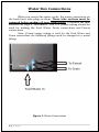
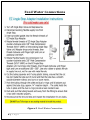
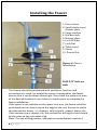
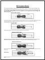
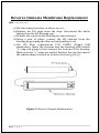
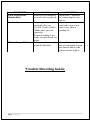
WATER BOX
OPERATION MANUAL
1|Page
Table of Contents
Introduction…….……………………………………………………………………………………..pg.3
Setting up the Water Box.……………………………………………………………………….pg.3
How The Water Box Works…….……………………………………………………………...pg.4
Water Connections………………….…………………………………………………………..…pg.5
Feed Water Connections………………………………………………………………….……p.g.6
Drain Connections………..……………………………………………………………………….p.g.7
Installing the Faucet…….……………….……………………………………………………..pg.8,9
Battery Installation……………………….…………………………………………………........pg.9
EZ Connections…………………………….……………………………………………………….pg.10
System Start Up………………………….…………………………………………………………pg.11
Filter Replacement…………………….………………………………………………………….pg.12
Reverse Osmosis Membrane Replacement.…………………………………….……pg.13
Troubleshooting……………………………………….………………………………………....pg.14
Specifications………………………………………….………………………………………..….pg.14
Warranty……………………………………………………….……………………………………..pg.15
List of Figures
Figure 1 Water Connections…………….. ………………...….…………………………….pg.5
Figure 2. Feed Water Connection………………….….………..………………………….pg.6
Figure 3. Drain Connection..………………….……….….……………..……………………pg.7
Figure 4. Faucet Installation…………..………………...…………………………………...pg.8
Figure 5. Reverse Osmosis Membrane Replacement…………………….……...pg.13
2|Page
Introduction
Congratulations on your purchase of our revolutionary purification
system, the Water Box! Our Reverse Osmosis system is designed to
replace the conventional 5 gallon water bottle while eliminating the
hassles of deliveries, lifting bottles and eliminating plastic bottles from
landfills.
The Water Box is connected to your city or well water supply to
efficiently filter out tastes and odor, and to remove microscopic
contaminants by using reverse osmosis purification technology. The
Water Box only dispenses room temperature water.
The “RO” system utilizes a CSM Reverse Osmosis water purification
filter which produces pure safe water from city or well water. The “RO”
assembly is comprised of 4 filters. The first stage is a 5-micron sediment
filter, a carbon (GAC) 10-micron filter, CSM RO membrane and a post
carbon filter to improve taste. The “RO” filter assembly requires a drain
line connection to be installed which removes rejected water to the
sewer.
Please read all the instructions in this manual before operating this unit.
Setting Up the Water Box
Connections that need to be made:
1. Setup your Feed water connection
2. Setup your Drain connection
3. Setup your faucet connection
After your connections are made you need to:
1. Install the batteries
2. Flush the filters
3|Page
How the Water Box works
The Water Box Reverse Osmosis (RO) System uses a semipermeable
membrane to reduce dissolved salts and minerals, improving the taste
and odor of your water. The RO membrane is made of layers of micronthin film wound around a hollow center core. Water molecules can pass
through the membrane, but dissolved salts and minerals are rejected.
The Water Box Reverse Osmosis System features 4-stage filter action.
Your water supply is pre-filtered to reduce dirt and chlorine that may
foul the membrane. The RO membrane separates this pre-filtered water
into PRODUCT WATER and DRAIN or REJECT WATER. Incoming water
pressure forces the product water through the membrane and into the
storage tank. Dissolved solids and other contaminants cannot pass
through the membrane and are sent to the drain as reject water. When
you open the drinking water faucet, product water is drawn from the
storage tank through an activated carbon post-filter, providing you with
cleaner, great-tasting water. For each gallon of water produced, several
gallons are discharged as reject water. The storage tank can hold up to 1
gallon of water at a time, for drinking and cooking needs.
Blue LED Light
The Blue LED light is used as a filter replacement indication light. The
batteries last about 6 months. This is about the same time filters need
to be replaced.
4|Page
Water Box Connections
When you receive the water cooler, the water connections on
the back have tube plugs in them. These tube sections must be
removed before making all your connections. To remove the tube
sections see Page 9 “Disconnect”. The 1/4" plastic tubing should be
used for making the Feed Water, Drain connections and Faucet
connections.
Note: If hard copper tubing is used for the Feed Water and
Drain connections the bulkhead fittings must be changed to a metal
fitting.
Figure 1. Water Connections
5|Page
Feed Water Connections
Figure 2. Feed Water Connection
6|Page
Drain Connection
(Applies to models with Reverse Osmosis “RO” only)
The drain line in the back (Fig. 4) must be hooked to the
drain line ahead of the normal sink water trap.
See Figure 3 below. Place the 2 part drain saddle on the drain pipe
before the drain trap. Allow proper space for the drilling operation.
Tighten the saddle bolts evenly on both sides. Using the opening in
the drain outlet saddle as a guide, drill a 1/4” hole in the drain pipe.
Clean any debris out of the drain saddle connection. Connect the
drain line to the cooler using the 1/4” black tubing supplied.
Figure 3. Drain Connection
7|Page
Installing the Faucet
1. Faucet base
2. Small washer and
chrome plate
3. Large washer
4. Kitchen sink
5. Bottom plate
6. Lock Washer
7. Lock Nut
8. Tube Insert
9. Sleeve
10. Faucet Nut
Figure 4. Faucet
Installation
Drill 5/8” hole on
sink
The Faucet should be positioned with aesthetics, function and
convenience in mind. An ample flat service is required for the faucet
base so that it can be drawn down tight. Also check the under sink area
of the desired location to see if there is ample space to complete the
faucet installation.
If the space is not available on the upper sink area, the faucet could be
positioned on the counter top at the edge of the sink. Be sure to watch
for obstructions below, i.e., drawers, cabinet walls, support braces etc.
If the counter top is ceramic tile, the method for drilling the hole should
be the same as for a porcelain sink.
Note: The sink drilling process, although not complicated, requires a
8|Page
certain amount of caution and forethought. Porcelain sinks can chip if
care is not exercised.
PORCELAIN ENAMEL SINK/ STAINLESS STEEL SINK/ ALUMIUM SINK
A 5/8” hole is required for the faucet. It is recommended that you get
special drill bit for porcelain and tile counter.
1. Place a piece of masking tape or duct tape on the determined
location where the hole is to be drilled.
2. Use a variable speed drill at slow speed with 1/8” drill bit, and drill a
centering hole in the center of the desired faucet location.
3. Enlarge the hole using a 1/ 4” drill bit.
4. Enlarge the hole using 7/16”, 1/ 2”, and 5/8” drill bit. Pause
occasionally to cool the drill bit.
5. File or clean the surrounding area and remove the masking or duct
tape. (NOTE: the metal chips on porcelain will stain very fast)
6. DON’T put Teflon tape at the tip of the threaded mounting base of
the faucet since it’s a compression fitting.
7. Put the small rubber washer, the chrome base plate, large rubber
washer according to the diagram through the threaded mounting tube
at the base of the faucet.
8. From under the sink, install the bottom plate, lock washer, and nut.
Then screw on tightly.
9. According to the diagram, put the brass nut through the BLUE tubing
first, then plastic sleeve (preferred), or brass sleeve, then the plastic
insert. Push the white plastic sleeve against the insert.
10. Screw on the Blue tubing with brass nut to the faucet base. Uses
wrench to tighten the nut but don’t over tighten it. Too tight would
cause leak.
11. The spout can swivel 360-degrees. The faucet lever can be pushed
down for dispensing or pulled up for continuing dispensing
Battery Installation
To install the batteries simply unscrew the top cover of the water box.
The 2 screws are located in the back of the Water Box on the top cover.
Install the batteries and LED light will illuminate.
9|Page
EZ Connections
The standard tubing connections on the water coolers are EZ connect fittings. Use
the tubing provided and follow the instructions below to make the connections. If
you cut the tubing, make sure it is a square cut, fits squarely in the fitting and
seals properly.
Cut the tube square
“O” Ring
Collet
Stainless Steel Teeth
Cut the tube square. It is essential that the outside diameter is free of score marks and that burrs and
sharp edges be removed before inserting into fitting. For soft thin walled plastic tubing we
recommend the use of a tube insert.
Insert tube
Fitting grips before it seals. Ensure tube is pushed into the tube stop.
Push up to tube stop
Push the tube into the fitting, to the tube stop. The collet (gripper) has stain-less steel teeth which
hold the tube firmly in position while the “O” ring pro-vides a permanent leak proof seal
Pull to check secure
Pull on the tube to check it is secure. It is good practice to test the system prior to leaving site and/or
before use.
Push in collet and remove tube
Push Collect in
Disconnect
10 | P a g e
Pull Tube Out
To disconnect ensure the system is depressurized before removing fitting. Push in collet squarely
against face of fitting. With the collect held in this position, the tube can be removed.
System Start-up
Once all your connections are complete you are ready to prime or flush
the filters. To do this simply turn on the water and open the faucet. You
will notice water coming out of the drain line. This is normal and will
stop when the Water Box is completely filled with water.
Let the system flush through the faucet for about an hour. In that time
you will notice fine black carbon particles. These particles are harmless,
but may make the water appear grey in color.
Note: The reverse osmosis membrane is treated with a food grade
sanitizing agent that may cause an undesirable taste. Although it is not
harmful, it should be flushed from the system.
NOTE: The RO system does not produce a high volume of water on
demand as an ordinary filter does. Water is produced at a slow, drop-bydrop rate. The system requires about 30 minutes to fill the storage tank.
As water is taken from the tank, the system automatically starts the
cycle of replacing the water and then stops water production when the
tank is full.
CAUTION: Visually check the entire system for leaks. If a leak is
present, make sure all of your connections are pushed in tightly.
NOTE: Initially, the water may appear cloudy. This is a result of air
trapped in the post-polishing filter. It is not harmful and will disappear in
a matter of minutes. It may take up to a week after installing a new
post-polishing filter for the trapped air to dissipate.
11 | P a g e
Water Box Filter Replacement
The filter elements must be replaced at regular intervals to
maintain the quality of the water.
The Water Box has 4 stages of Reverse Osmosis filtration. The
first stage is the 5-micron sediment filter. The second stage is the
activated carbon filter. The third stage is the post carbon filter. These
filter elements must be replaced every six months. The Reverse
Osmosis filter; the larger of the 3 must be replaced every 3 years.
Replacement Procedures, Filtration Versions
a) Turn your water supply off going to the Water Box.
b) Unscrew the 3 covers with a Phillips head screwdriver.
c) Turn the blue valve on the holding tank to the off position.
d)Place a towel under the filters to catch water. The filters will
have water in them which will run out when the filters are
unlocked.
e) Twist the filters to remove them from their housings.
f) These filters are disposable, encapsulated filters. Remove and
discard the entire filter body. Replacement filters are sold as a
set:
1st Stage sediment filter
2nd Stage carbon filter
3rd Stage post carbon
P/N ETSET
f) Twist new filters on the housing brackets.
g) Turn the blue valve on the tank back to the on position.
h) Open the water supply and let water flow through filters.
Leave the faucet on and let the water activate the filters for 1
hour.
i) Let the Water Box fill up ensuring you don’t have any leaks
then re-install the panels.
12 | P a g e
Reverse Osmosis Membrane Replacement
(RO) (every three years)
a) Use the same procedure as above sec a-c.
b) Remove the RO stage from the clips. Disconnect the white
tubing from the RO housing cap.
c) Remove the cap from the housing by unscrewing it.
d) Using a pair of pliers, remove the RO element from the
housing by grasping the tube end and pulling it out.
e) Use RO filter replacement P/N CSM50 (50gpd CSM
membrane). Insert the element into the housing with double
“o”-ring end going in first–toward the bottom of the housing.
Make sure the “o”-rings are sealed. Replace the cap. Reconnect
the white tubing. Proceed as in above section (g) to (i)
Figure 5. Reverse Osmosis Replacement
13 | P a g e
PROBLEM
LED Light is not
illuminated
CAUSE
Batteries not installed
or need to be replaced.
Leaks at connections
Depress plastic collar
and pull tube out.
Cut off 1 inch of tube.
(Make sure you cut
squarely).
Reinsert tubing, turn
water on and check for
leaks.
Filters need to be
Once all connections
primed (flushed).
have been made. Open
the faucet and let the
water run through it
Water Tastes Bad
SOLUTION
Install the 2 batteries
by removing the top
cover.
Open the water box
and make sure each
and every tube is
pushed in.
Trouble Shooting Guide
14 | P a g e
for 1 hour.
Note - In the event of problems beyond the scope of the troubleshooting described in the
manual, please call your selling dealer.
Specifications
Model No.
Water Box
High Side Pressure
125 psi
Low Side Pressure
15 psi
Ambient Tank Capacity
2.3 Gallons
Warranty
All Global Water products are warranted to be free from defects
in materials and workmanship under normal use within the
condition of operation listed for a period of 1 year from date of
purchase.
There is no liability assumed by the company for damage due to
water leakage or other secondary effects from any component
defect. Labor is not covered in this warranty. The warranty applies
when “Conditions of Operation” below are met.
Conditions of Warranty
Water System Pressure 35 -100psi, Temperature, 40 -100degrees F,
Water PH range 4-10, Max. TDS 1500 PPM, Turbidity, <1.0 NTU,
15 | P a g e
Water Hardness < 20gpg, Iron <0.1 mg/l, Manganese <0.1 mg/l,
Hydrogen Sulfide < 0.00 mg/l
*For filter only systems (“F” models), water hardness must be less
than 3.5 grains or 60 mg/liter
16 | P a g e
Cleaner, Healthier Water.
3937 Pembroke road,
Hollywood, Florida 33021
www.Bluline.com
Tel. (786) 235-2518
Fax (786) 207-2570
Email [email protected]
17 | P a g e