1
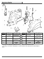
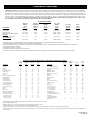
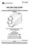
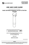
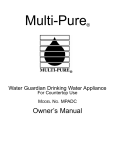
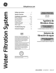
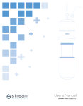
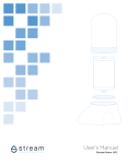
US Item# 1001 104 032 CAN Item# 1000803392 US Model # HDGDUS4 CAN Model # HCGDUS5 USE AND CARE GUIDE ADVANCED DEFENSE DRINKING WATER FILTRATION SYSTEM Questions, problems, missing parts? Before returning to the store, call Glacier Bay Customer Service 7 a.m. - 6 p.m., CST, Monday - Friday 1- 800800- 247247 -1087 HOMEDEPOT.COM/GLACIER HOMEDEPOT.COM/GLACIERBAY /GLACIERBAY System tested and certified by NSF International against NSF/ANSI Standards 42 & 53. See performance data sheet for details. NSF ® 201-8401432 (rev 00) THANK YOU We appreciate the trust and confidence you have placed in Glacier Bay through the purchase of this drinking water filtration system. We strive to continually create quality products designed to enhance your home. Visit us online to see our full line of products available for your home improvement needs. Thank you for choosing Glacier Bay! Table of Contents Safety Information .................................2 Warranty .................................................2 Pre-Installation ......................................3 Installation .............................................5 Filter Cartridges .................................... 8 Faucet Timer and Battery ..................... 9 Troubleshooting .................................... 9 Service Parts ....................................... 10 Safety Information Read all instructions before installing and using your home water filtration system. Follow all steps exactly to correctly install. Reading this manual will also help you to get all the benefits from the filtration system. WARNING:: Do not use with water that is microbiologically unsafe or of unknown quality without adequate disinfection before or after the system. CAUTION:: Do not install the filtration system outside, or in extreme hot or cold temperatures. Temperature of the water supply to the filtration system must be between 40°F and 100°F. Do not install on a hot water line. All plumbing must be completed in accordance with national, state and local plumbing codes. Local code information can be obtained at your local public works department. In Massachusetts, plumbing code 248 CMR 3.00 and 10.00 shall be adhered to. Consult with your licensed plumber. NOTICE:: This filtration system works on water pressures of 30 psi (minimum) to 100 psi (maximum). If your house water pressure is over the maximum, install a pressure reducing valve in the water supply pipe to the filtration system. Warranty GLACIER BAY WATER FILTRATION FILTRATION SYSTEMS - WARRANTY Glacier Bay Water Filtration Systems are manufactured under the highest standards of quality and workmanship. Glacier Bay Water Filtration Systems warrants to the original purchaser that this system will be leak and drip free during normal domestic use for a period of one (1) year from date of purchase. If this system should ever develop a leak or drip Glacier Bay Water Filtration Systems will free of charge provide the parts necessary to put the system back in good working condition. A replacement for any defective part will be supplied free of charge for installation by the purchaser. Defects or damage caused by use of other than authorized parts are not covered by this warranty. This warranty shall be effective from date of purchase as shown on purchaser’s receipt. Glacier Bay Water Filtration Systems shall be installed per the manufacturer’s installation instructions and specifications. Some states do not allow limitations on how long a warranty lasts, so the above limitation may not apply to you. This warranty is valid for the original purchaser only and excludes industrial, commercial, or business use of the product, product misuse, and product damage due to installation error, whether performed by a contractor, service company, or yourself. Glacier Bay Water Filtration Systems will not be responsible for labor charges or for damage incurred during installation, repair or replacement, nor for incidental or consequential damages. Some states, provinces and nations do not allow the exclusion or limitation of incidental or consequential damages, so the above exclusions or limitations may not apply to you. Glacier Bay Water Filtration Systems will advise you of the procedure to follow in making warranty claims. Simply write to Glacier Bay Water Filtration Systems at the address below. Explain the defect and include proof of purchase and you name, address and telephone number or you can also call us at 1-800-247-1087. U.S.A Canada Glacier Bay Water Filtration Systems Glacier Bay Water Filtration Systems 2455 Paces Ferry Road, N.W. 900-1 Concorde Gate Atlanta, GA 30339-4024 Toronto, ON M3C 4H9 2 Pre-Installation INSTALLATION LOCATION LOCATION Install the water filtration system on the cold water supply pipe, under the kitchen and/or bathroom sink, to filter the cold drinking water. Refer to this diagram: Faucet Blue water OUT SINK Supply fitting Yellow water IN Shutoff valve HOT COLD DIMENSIONS 16 in. 12 in. 5 in. 15 1/8 in. SPECIFICATIONS Minimum – Maximum Supply Water Pressure Minimum – Maximum Supply Water Temperature Inlet – Outlet 30 – 100 PSI (207 – 689 kPa) 40 - 100°F (5 - 38°C) 3/8 in. quick connect fittings and tubing included TOOLS REQUIRED Phillips screwdriver Pliers Adjustable wrench Tubing cutter Drill and 1-1/4 in. drill bit Sealant tape 3 HOMEDEPOT.COM/GLACIERBAY Please contact 1-800-247-1087 for further assistance. Pre-Installation (continued) PACKAGE CONTENTS D E C Part A B C D E Description Filtration system Water supply fitting Filtered water faucet for sink/countertop mounting 3/8 in. tubing (used for all connections) Filter cartridge 4 Quantity 1 1 1 1 2 Installation 1 Connecting the feed water supply fittings Check and comply with local plumbing codes as you plan and install a cold feed (supply) water fitting. The fitting must provide a leak-tight connection to the water filter 3/8 in. tubing (D). A typical connection using the water supply fitting (B) is shown in Figure A. An optional connection using standard plumbing fittings (not included) is shown in Figure B. Installation using the Fitting (Figure A): □ Close the water shut off valve that is immediately before the supply fitting and open faucets to drain water from the cold water pipe from the sink. □ Remove the nut that connects the cold water faucet to cold water plumbing. □ Thread the water supply fitting (B) onto the pipe and reconnect the nut to the bottom of the fitting. Installation using Optional Pipe Fittings (compression type shown – Figure B): □ Turn off the water supply and open a faucet to drain the pipe. □ Install a fitting on the cold water pipe to adapt to the 3/8 in. OD tubing. □ If threaded fittings are used, be sure to use pipe joint compound or thread sealing tape on outside threads. Cold water faucet stud B Thread sealing tape on threads D Cold water pipe Figure A Cold water shutoff Cold water shutoff 3/8 in. Compression fitting Cold water pipe Figure B Insert 3/8 in. tubing to Water Filter inlet Ferrule l 5 HOMEDEPOT.COM/GLACIERBAY Please contact 1-800-247-1087 for further assistance. Installation (continued) 2 Installing the faucet IMPORTANT:: To avoid damaging the sink, consult a qualified plumber or installer for drilling procedures in porcelain or stainless steel. Special drill bits are made for this. Before you begin, ensure there is room underneath the sink or countertop so you can make the needed connections. If drilling is required in the sink top or countertop next to the sink, make a 1-1/4 in. dia. (minimum) hole for the faucet (C). □ Insert one end of the blue tube into the faucet (C) (see Step 3 – Connecting the tubes). Feed the other end of the blue tube through the mounting hole. □ Slide the toggle bolts through the mounting hole until the faucet (C) base is square against the mounting surface (sink or countertop). Tighten the toggle bolts to secure the base flat on the mounting surface. Do not over-tighten. □ Turn the faucet 1/4 clockwise to attach the faucet (C) to the base. 3 C 1/4 turn to connect faucet to base Screw Toggle bolt Faucet base Rubber washer Hole in sink or counter Push in fitting Connecting the tubes Foam plug Remove and discard the protective foam plugs (if present) before connecting tubes. □ Allowing some slack, measure and cut a length of 3/8 in. tubing (D) to connect between the supply fitting and the filter system inlet. Cut the ends of the tubing square. □ Insert tubing all the way into the supply fitting and inlet fitting. Pull on the tubing to be sure that it is securely set in the fittings. □ Repeat the first two bullets to connect the tubing from the faucet to the filter system outlet. Tubing Connection Connection (all pushpush -in fittings): fittings): This system includes push-in fittings for quick tubing connections. If working with the fittings, do the following: □ Cut the end of the tubing square. Inspect the end (about 1 in.) of the tubing to be sure there are no nicks, scratches or other rough spots. If needed, cut the tubing again. □ Push tubing through the collet and through the fitting. Full engagement is 3/4 in. length of tube into the fitting. If tubing other than supplied with the system is used, be sure it is of high quality, exact size and roundness with a smooth surface. Remove and discard foam plugs Tubing correctly cut and connected End of tubing round and smooth, with no cuts, nicks or flat spots Correct full 3/4 in. engagement Incorrect partial engagement To disconnect, push the collet inward and hold with a finger while pushing the tubing out: 6 Installation (continued) 4 5 Installing the filter cartridges □ Remove the plastic cap from the filter cartridges (E). □ Install the filter cartridges (E) into the two holes in the filter body. Note the filter cartridges are labeled Filter 1 and Filter 2. Turn clockwise to tighten. Do not over tighten. E Completing the installation □ Open the shutoff valve that you closed at the beginning of this installation. □ Open the filtered water faucet (C) to purge air from the system. When the water runs smooth with no bubbles or spurting close the faucet (C) and check the installation for leaks. □ Open the filtered water faucet (C) and let water run for 10 minutes to rinse system. A 7 HOMEDEPOT.COM/GLACIERBAY Please contact 1-800-247-1087 for further assistance. Filter Cartridges FILTER CARTRIDGE LIFE LIFE The filter cartridge contains activated carbon, a black powder. When new, open the filtered water faucet and allow fine, carbon particles to purge from the cartridge. Close the faucet when you no longer see the “fines” (carbon particulates) in the filtered water, or approximately 10 minutes. It is recommended to replace the battery and filter cartridges every six months of use. There are several variables that determine how long a cartridge will last. These include: 1. How much water you use, and 2. How much sediment, taste and/or odor, or other unwanted substance, is in the water. Use the following information as a guide. However, no matter which type of filter cartridge you are using, you will know it is time to replace it when you first notice the return of the unwanted substance in your water. Glacier Bay Advanced Defense Water Filtration System model HDGDUS4/HCGDUS5 with replacement filter element pack HDGDUF4/HCGDUF5 conforms to NSF/ANSI 42 and 53 for the specific performance claims as verified and substantiated by test data. The rated capacity for this system is 270 gallons (1022 liters) at a rated service flow of 0.5 gpm (gallons per minute). FILTER CARTRIDGE REPLACEMENT REPLACEMENT 1. Turn the filter cartridges counterclockwise to remove and dispose of them properly. 2. Install the new filter cartridges by turning them clockwise. 3. Remove and replace the timer battery. See the Changing the Faucet Battery section for more information. The filter cartridge contains activated carbon, a black powder. When new, open the filtered water faucet and allow the fine carbon particles to purge from the cartridge. Close the faucet when you no longer see the “fines” in the filtered water, or approximately 10 minutes. Turn filter cartridge clockwise to install Turn filter cartridge counterclockwise to remove 8 Faucet Timer and Battery FAUCET TIMER Inside the faucet base is a battery-operated 6 month timer. An amber LED indicator is also located in the front of the faucet base. This LED flashes continuously after 6 months have passed. This indicates that it is time to replace the battery and filters. CHANGING THE FAUCET BATTERY To change the battery, complete the following steps: 1. Loosen the screw on the right side of the faucet base. 2. Press the battery housing upwards from the faucet base until it releases from the base. 3. Replace the battery (CR 2032 or equivalent). Place battery into the holder with the positive (+) side facing the back of the holder. 4. When the battery is first replaced, the light in the base will flash six times and turn off. This indicates the battery is fully charged. After the six flashes, the timer enters the 6 month time cycle. If it repeatedly flashes two times, the battery is weak and needs to be replaced. 5. Re-install the battery housing and firmly tighten the mounting screw. Battery housing Battery negative (-) side facing the front Screw Troubleshooting Problem The water tastes bad and has an odor. Probable Cause The filters are expended. The system is contaminated. Faucet LED indicator light does not function after a battery change. The battery is dead. The battery is not installed correctly. Water leaks at the push connect fittings. The tubing is not pushed in all the way. The tubing is not cut square. The tubing is nicked. The outer tubing surface is not smooth. 9 Solution Replace the filter cartridges. Sanitize the system. Call 1-800-2471087 for instructions. Replace the battery. Install the battery correctly, paying attention to the polarity. Push the tubing in all the way into fittings. Cut the tubing square. Remove the nicked portion and reinsert the tubing into the fitting. Remove the rough portion, and reinsert the tubing into the fitting. HOMEDEPOT.COM/GLACIERBAY Please contact 1-800-247-1087 for further assistance. Service Parts Key Number 1 Part Number Description 119-8600048 Faucet with base and electronics Cabinet, left 2 1073-23-01 3 1073-23-HC 4 1073-23-05 5 Key Number 6 Head assembly (includes #5) Elbow fitting 3/8 x 3/8 in. coupler Part Number Description 1073-23-02 Cabinet, right 7 HDGDUF4/HCGDUF5 8 7228536 9 1073-22-09 ** 7157280 Replacement filter cartridge, 2-pack* Tee, feed adapter 3/8 x 3/8 in. union, yellow Tubing, 3/8 in. x 20 ft., white *Please purchase replacement cartridges from the retailer where you purchased this system. ** This tubing is not included. Tubing lengths for remote installation, direct replacement for colored lengths of tubing. 10 Questions, problems, missing parts? Before returning to the store, call Glacier Bay Customer Service 7 a.m. - 6 p.m., CST, Monday-Friday 1- 800800- 247247-1087 HOMEDEPOT.COM HOMEDEPOT.COM/ .COM /GLACIERBAY Retain this manual for future use. Manufactured by Ecodyne Water Systems 1890 Woodlane Drive Woodbury, MN 55125 Performance Data Sheet Model HDGDUS4/HCGDUS5 Drinking Water Filter IMPORTANT NOTICE: Read this Performance Data Sheet and compare the capabilities of this unit with your actual water treatment needs. It is recommended that, before purchasing a water treatment unit, you have your water supply tested to determine your actual water treatment needs. This filter system is designed to be used for the reduction of the performance claims listed below. Do not use where water is microbiologically unsafe or of unknown quality, without adequate disinfection before or after the system. Systems certified for cyst reduction may be used on disinfected water that may contain filterable cysts. While testing was performed under standard laboratory conditions, actual performance of the system may vary based on local water conditions. Some or all of the contaminants reduced by this unit may not be in your water supply. See Use and Care Manual for further instructions on filter cartridge replacement, system installation, operating procedures, and warranty. The maintenance instructions must be followed for the product to perform as indicated below. Performance Claims Contaminant Cyst Lead @ pH 6.5 Lead @ pH 8.5 Methyl tert-Butyl Ether (MTBE) Substance Chlorine Taste, and Odor VOC Reduction7 Chloroform Required Influent Level (mg/L)2 50000 #/mL4,5 0.15 10% 0.15 10% 0.015 20% NSF Max. Permissible Eff. Level (mg/L)2 99.95%3 0.010 0.010 0.005 Average Influent Level (mg/L)2 93,000#/mL4 0.152 0.150 0.01467 Avg. / Max. Effluent Level (mg/L)2 <1 /< 4 #/mL4 0.001/ 0.001 0.001. / 0.001 0.0005. / 0.0005 Avg. / Min. Percent Removal 99.99 / 99.99 99.3 / 99.3 99.3 / 99.3 96.2 / 96.2 EPA1 MCL (mg/L)2 None7 0.015 0.015 None6 2.0 10% 50%3 2.0 0.05 / 0.08 97.5 / 96.2 None6 0.30 10% 95%3 0.320 0.0005 / 0.0005 99.8 / 99.8 0.080 1 EPA MCL means Environmental Protection Agency Maximum Contaminant Level as required under the Safe Drinking Water Act. mg/L means Milligrams Per Liter, which is equivalent to parts per million (PPM). NSF minimum percent reduction requirement. Acceptance level for this substance is based on percent reduction rather than maximum effluent concentration. 4 #/mL means particles per milliliter. 5 Microspheres was used as a surrogate 6 The EPA has not determined an MCL for this chemical. 7 Chloroform was used as a surrogate for the reduction of chemicals specified in the Organic Chemicals Reduced by Chloroform Surrogate Testing table. 2 3 Organic Chemicals Reduced by Chloroform Surrogate Testing Contaminant Alachlor Atrazine Benzene Carbofuran Carbon Tetrachloride Chlorobenzene Chloropicrin 2,4-D Dibromochloropropane (DBCP) o-Dichlorobenzene p-Dichlorobenzene 1,2-Dichloroethane 1,1-Dichloroethylene cis-1,2-Dichloroethylene trans-1,2-Dichloroethylene 1,2-Dichloropropane cis-1,3-Dichloropropylene Dinoseb Endrin Ethylbenzene Ethylene Dibromide (EDB) Haloacetonitriles (HAN): Bromochloroacetonitrile Dibromoacetonitrile Dichloroacetonitrile Trichloroacetonitrile Average1 Influent (g/L)2 50 100 81 190 78 77 15 110 52 80 40 88 83 170 86 80 79 170 53 88 44 Maximum Effluent (g/L)2 1.03 3.03 1.03 1.03 1.84 1.03 0.24 1.74 0.023 1.03 1.03 4.85 1.03 0.53 1.03 1.03 1.03 0.24 0.594 1.03 0.023 Percent Removal >98 >97 99 >99 98 99 99 98 >99 99 98 955 99 >99 99 99 99 99 99 99 >99 22 24 9.6 15 0.54 0.64 0.24 0.34 98 98 98 98 EPA MCL (g/L)2 2.0 3.0 5.0 40 5.0 100 NA 70 0.2 600 75 5.0 7.0 70 100 5.0 NA 7.0 2.0 700 0.05 NA NA NA NA NA Contaminant Haloketones (HK): 1,1-dichloro-2-propanone 1,1,1-trichloro-2-propanone Heptachlor Heptachlor Epoxide Hexachlorobutadiene Hexachlorocyclopentadiene Lindane Methoxychlor Pentachlorophenol Simazine Styrene 1,1,2,2-Tetrachloroethane Tetrachloroethylene Toluene 2,4,5-TP (silvex) Tribromoacetic acid 1,2,4-Trichlorobenzene 1,1,1-Trichloroethane 1,1,2-Trichloroethane Trichloroethylene Trihalomethanes (includes): Chloroform (surrogate chemical) Bromoform Bromodichloromethane Chlorodibromomethane Xylenes (total) Average1 Influent (g/L)2 Maximum Effluent (g/L)2 Percent Removal 7.2 8.26 25 10.76 44 60 55 50 96 120 150 81 81 78 270 42 160 84 150 180 300 0.14 0.34 0.013 0.26 1.03 0.0023 0.013 0.13 1.03 4.03 0.53 1.03 1.03 1.03 1.63 1.03 0.53 4.64 0.53 1.03 15 99 96 >99 98 98 >99 >99 >99 99 97 >99 99 99 99 99 98 >99 95 >99 >99 95 EPA MCL (g/L)2 NA NA NA 0.4 0.2 NA 50 0.2 40 1.0 4.0 100 NA 5.0 1,000 50 NA 70 200 5.0 5.0 80 70 1.03 99 10,000 1 Influent challenge levels are average influent concentrations determined in surrogate qualification testing. g/L means Micrograms Per Liter. Maximum product water level was not observed but was set at the detection limit of the analysis. 4 Maximum product level is set at a value determined in surrogate qualification testing. 5 Chemical reduction percent and maximum product water level calculated at chloroform 95% breakthrough point as determined in surrogate qualification testing. 6 The surrogate test results for heptachlor Epoxide demonstrated a 98% reduction. These data were used to calculate an upper occurrence concentration, which would produce a maximum product water level at the MCL. 2 3 02/20/15 (Rev. 01) 201-8401976 General Information Installation Requirements This filter improves the taste and odor and reduces many chemical contaminants in drinking water. The faucet indicator monitors the length of time the filter has been installed and will flash amber continuously; indicating the filters and battery need to be replaced. This system has been tested according to NSF/ANSI 42 and 53 for the reduction of the substances listed on the previous page. The concentration of the indicated substances in water entering the system was reduced to a concentration less than or equal to the permissible limit for water leaving the system, as specified in NSF/ANSI 42 and 53. The testing was performed using spiked tap water at a flow rate of 0.5 GPM (1.9 L/min.), pH of 7.5 0.5, pressure of 60 PSIG, and temperature of 68 5F. Manufactured and warranted by: Ecodyne Water Systems 1890 Woodlane Drive Woodbury, MN 55125 Pressure Range ......................................................................30-125 psig (2.1-8.8 kg/cm2) Temperature Range ...................................................................... 40-100F (5-38C) Service Flow Rate ............................................................................... 0.5 GPM (1.9 LPM) Service Life .............................................................................. 270 Gallons (1,022 Liters) Maintenance Refer to Use and Care Manual for warranty and further details on installation and maintenance. Cartridges should be replaced every 270 gallons or six months, whichever comes first. For replacement elements, call 1-800-247-1087 or contact your nearest The Home Depot’s store. Replacement filter prices will vary. Current pricing replacement filters HDGDUF4/HCGDUF5 I and II is approximately $30.00 to $50.00 per filter element. System Tested and Certified by NSF International against NSFI/ANSI Standard 42 for the reduction of chlorine, taste and odor and Standard 53 for the reduction of cyst, lead, MTBE, and VOCs. FOR IOWA ONLY All sales in Iowa require the following signature before consummation of sale. These signatures must be retained by seller/renter for 2 years minimum. Buyer/Renter ______________________ Date Seller Date Sellers Address Sellers Phone # Product: GLACIER BAY Drinking Water Filter Model HDGDUS4 02/20/15 (Rev.01) 201-8401976