1
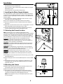
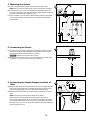
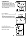
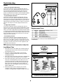
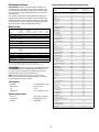
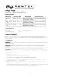
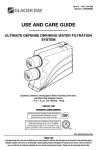
Monitored Dual Filtration System
Installation and Operating Instructions
Model US-1500 (with electronic monitor)
Specifications
Temperature Range:
Pressure Range:
Service Flow Rate @ 60 psi (4.1 bar):
Rated Service Life:
Dimensions:
Weight:
40–100°F (4.4–37.8°C)
30–125 psi (2.1–8.62 bar)
0.6 gpm (2.3 L/min)
1,000 gallons (3,785L)
9.18 in. x 4.70 in. x 12.72 in.
(233 mm x 119 mm x 323 mm)
6 lbs. (2.7 kg) (filled with water)
Parts Included
•
•
•
•
•
•
Filter system with filter cartridges – P-250 Cartridge Set
Installation hardware
(mounting screws, T-Adapter, quick-connect elbows)
Electronic monitor and 9-volt battery
Housing wrench
Lead-free drinking water faucet
1/4" plastic tubing
Precautions
WARNING: Do not use with water that is microbiologically unsafe
or of unknown quality without adequate disinfection before or after
the system. Systems certified for cyst reduction may be used on
disinfected waters that may contain filterable cysts.
CAUTION: Filter must be protected against freezing, which can
cause cracking of the filter and water leakage.
CAUTION: The rubber O-ring provides the water-tight seal between
the cap and the bottom of the housing. It is important that the O-ring
be properly seated in the groove below the threads of the housing or a
water leak could occur.
CAUTION: Because of the product’s limited service life and to
prevent costly repairs or possible water damage, we strongly
recommend that the bottom of all plastic housings be replaced every
ten years. If the bottom of your housing has been in use for longer
than this period, it should be replaced immediately. Date the bottom of
any new or replacement housing to indicate the next recommended
replacement date.
NOTE:
• For cold water use only.
• Make certain that installation complies with all state and local
laws and regulations.
• The contaminants or other substances removed or reduced by
the selected cartridge are not necessarily in your water. Ask your
local water municipality for a copy of their water analysis, or have
your water tested by a reputable water testing lab.
• After prolonged periods of non-use (such as during a vacation) it
is recommended that the system be flushed thoroughly. Let water
run for 5–6 minutes before using.
• The filter cartridges used with this system have a limited service
life. Changes in taste, odor, and/or flow of the water being filtered
indicate that the cartridge should be replaced.
About Your PENTEK Dual Filtration
System
Thank you for purchasing a PENTEK Dual Filtration System. With only
minimal maintenance, your new system will provide you with safer,
better-tasting water for years to come. The filter cartridges should be
changed after every 1,000 gallons of use or once every twelve months,
whichever comes first. Filter life will vary depending on usage and
water conditions. Changes in taste, odor, and/or flow of the water
being filtered indicate that the filter cartridges should be replaced.
Tools and Materials
Required
• Safety glasses
• Hand or electric drill
(cordless recommended)
• 1/4" drill bit
• File
• Phillips head screwdriver
• Adjustable wrench or 7/16”
open-end wrench
• Tube cutters or utility knife
If sink does not have hole
for separate faucet:
• Center punch
• 3/4" drill bit or hole saw
The Model US-1500 is Tested and Certified by NSF
International against NSF/ANSI Standard 42 for the reduction
of Taste and Odor, Chlorine, and Particulate Class I. Standard
53 for the reduction of Lead, Mercury, VOC, Cyst, Asbestos,
and Turbidity.
Technical Support: 800.861.8758 (M-F 7:30 a.m. - 5:00 p.m. CST)
146600 JA05
Installation
•
•
•
For standard under-sink installation on 1/2"-14 NPS threads (most common
thread on kitchen faucets) cold water line.
Please read all instructions and precautions before installing and using your
Dual Filtration System.
Numbered diagrams correspond with numbered steps.
D
1. Installing the Water Supply Adapter
The supply adapter fits 1/2"-NPS supply threads. If local codes permit, it may be
used to connect the US-1500 to the cold water supply line. If local codes do not
permit the use of the supply adapter, alternate connectors can be obtained from
your local supplier.
(A) Turn off cold water supply line. If cold water line does not have a shut-off
valve under the sink, you should install one.
(B) Turn on the cold water faucet and allow all water to drain from line.
(C) Disconnect cold water line from 1/2"-14 NPS threaded stub on bottom of
main faucet.
(D) Apply Teflon® tape onto threads of faucet stub and supply adapter. Screw the
water supply adapter to the threaded faucet stub as shown.
(E) Using the nut that previously connected the cold water line to the faucet,
screw the cold water line to the male supply adapter threads.
2. Selecting the Faucet Location
NOTE: The drinking water faucet should be positioned with function,
convenience, and appearance in mind. An adequate flat area is required to allow
faucet base to rest securely. The faucet fits through a 3/4" hole. Most sinks have
pre-drilled 13⁄8" or 11⁄2" diameter holes that may be used for faucet installation. If
these pre-drilled holes cannot be used or are in an inconvenient location, it will
be necessary to drill a 3/4" hole in the sink to accommodate the faucet.
CAUTION: This procedure may generate dusts which can cause severe
irritation if inhaled or come in contact with the eyes. The use of safety glasses
and respirator for this procedure is recommended.
CAUTION: Do not attempt to drill through an all-porcelain sink. If you have an
all-porcelain sink, mount the faucet in pre-drilled sprayer hole or drill through
countertop next to sink.
CAUTION: When drilling through a countertop make sure the area below the
drilled area is free of wiring and piping. Make certain that you have ample room
to make the proper connections to the bottom of the faucet.
CAUTION: Do not drill through a countertop that is more than 1" thick.
CAUTION: Do not attempt to drill through a tiled, marble, granite or similar
countertop. Consult a plumber or the countertop manufacturer for advice or
assistance.
(A) Line bottom of sink with newspaper to prevent metal shavings, parts, or tools
from falling down drain.
(B) Place masking tape over the area to be drilled to prevent scratches if drill bit
slips.
(C) Mark hole with center punch. Use a 1/4" drill bit for a pilot hole, then, using
a 3/4" drill bit or hole saw, drill a hole completely through the sink. Smooth
rough edges with a file.
3. Mounting the Faucet
(A) Remove wing nut and metal washer from the threaded shaft of the faucet.
Leave the black rubber washer on the threaded shaft.
(B) Slide the threaded shaft of the faucet into drilled hole.
(C) From under the sink, slide the metal washer on and thread on the wing
nut. Tighten the wing nut by hand until tight. It may be necessary to have a
second person to hold the faucet while tightening the wing nut.
NOTE: Do not overtighten the wing nut. Hand tighten only. Do not use pliers
or wrench to tighten.
2
B
1
A
C
E
2
C
B
A
3
Black
Rubber
Washer
Metal
Washer
Wing Nut
4. Mounting the System
(A) Center system between water supply adapter and drinking water faucet.
NOTE: Allow 11⁄2" (38 mm) clearance below system for changing filter cartridges.
(B) Install mounting screws at least 133⁄4" (350 mm) from cabinet floor and 41⁄8" (124
mm) apart. Leave enough space (approximately 1/2" [13 mm]) between the head of
the screw and the wall to slip system onto screws.
(C) Place system over screws on wall and slide downwards to lock into place. Make
certain system is firmly attached to wall to prevent it from falling and possibly
being damaged.
4
B
133⁄4"
(350mm)
C
A
11⁄2" (38mm)
5. Connecting the Faucet
(A) Insert one end of the 1/4" tube, supplied in the installation kit, into the gray quickconnect fitting collar located on the bottom of the threaded shaft of the faucet.
Push tubing into the fitting until you come to a hard stop.
CAUTION: Do not bend or crimp tube when inserting.
(B) Gently pull back on the tube to ensure it is connected properly. If the tube comes
out of fitting, cut a small section of the tube off and reconnect.
6. Connecting the Supply Adapter and Inlet of
Filter
(A) Determine the length of plastic tubing needed to connect the inlet (left) side of the
filter with the supply adapter. Be sure to allow enough tubing to prevent kinking
and cut the tubing squarely. Place a mark 5/8" from the end of the tubing.
(B) Wet tubing with water and insert into supply adapter 5/8" until mark is flush with
fitting.
NOTE: Disconnecting the Tubing from the Quick-Connect Fittings.
Routine maintenance and cartridge replacement will not require that you
disconnect the tubing from the filter system; however, tubing may be quickly and
easily removed from the fitting if necessary. First, turn off the water supply to the
filter. Open faucet, then press in the grey collar around the fitting while pulling the
tubing with your other hand.
3
5
6
A
5/8"
(16mm)
5/8"
(16mm)
B
7. Connecting the System
(A) Assemble tubing with system as shown in Fig. 7A, inserting tubing into
appropriate inlet or outlet quick-connect fitting until it stops.
7
NOTE: In some installations, connecting the system to the water supply
adapter and/or drinking water faucet causes the tubing to enter the quickconnect fitting at a sharp angle. This may exert pressure on the quickconnect fitting and cause it to leak. In these situations, you may wish to use
one or both of the quick-connect elbows included with the installation kit.
Simply push the quick-connect elbow directly into the quick-connect fitting
on the system, then insert the tubing into the quick-connect elbow.
(B) When cut between a set of black guide arrows, the tubing should be pushed
into the fitting so that the entrance of the fitting falls between the next set of
guide arrows (approximately 5/8" [16 mm]).
8. Installing the Battery
(A) Remove cover on top of system. Attach 9-volt battery (included) to connector,
then place battery in holder located to the left of the monitor panel as shown
(Fig. 8A).
(B) Replace cover on top of system. Using a pen or pencil, press and release the
blue reset button on the front of the system (Fig. 8B). The electronic monitor
should beep twice. If the monitor has been reset properly, the two beeps will
be followed by a sequence of two green, two yellow, and two red lights. The
monitor should be reset whenever a new set of filter cartridges is installed.
9. Putting the System into Operation
(A)
(B)
(C)
(D)
Slowly turn on cold water supply.
Shut off faucet opened before starting installation.
Open water supply adapter.
Rotate base of drinking water faucet counter-clockwise to “ON” position.
Allow water to run for 5 minutes to flush air and carbon fines from filter
cartridges. Check system for leaks before leaving installation.
INSTALLATION IS NOW COMPLETE.
8
A
9
B
D
C
A
4
Electronic Monitor Operations
Filter Cartridge Replacement
The US-1500 system includes an electronic monitor that alerts you
when it is time to change your filter cartridges. Both filter cartridges
should be changed at the same time to ensure that the monitor works
properly. The monitor measures actual water usage and is powered
by a single 9-volt battery.
•
•
1.
How the Electronic Monitor Works
The filter cartridges in the US-1500 should be replaced every 1,000
gallons. The electronic monitor uses a combination of lights and
alarms to alert you at different stages during the life of the filter
cartridges. The lights are visible on the front panel of the filter system,
to the left of the blue reset button:
2.
3.
0-950 gallons
No alarm. Green light flashes when water is turned on.
950-1000 gallons
4.
Alarm BEEPS ONCE when water is turned on. Yellow light flashes
when water is on.
1000+ gallons
Alarm BEEPS TWICE when water is turned on. Red light flashes when
water is on.
5.
Low or Dead Battery
6.
No alarm. No lights. Replace battery.
NOTE: Gallons used while battery is dead will register on meter when
battery is replaced
7.
NOTE: To extend battery life, any sequence that includes any beeps
will not be repeated if water is turned on again in less than 15 minutes.
8.
Reset Button
9.
The blue reset button is located on the front panel of the system.
This button should only be pressed during initial installation or when
new filter cartridges are installed. After pressing and releasing
the button, you will hear two beeps followed by a sequence of two
green, two yellow, and two red lights. This combination of beeps and
lights indicates that the system has properly reset the internal gallon
counter.
Filter cartridges the US-1500 will last about 1,000 gallons or twelve
months before they need to be replaced. Filter cartridge life
varies depending on usage, and/or water conditions. Changes in
taste, color, and flow of the water being filtered indicate that the
cartridge should be replaced.
Read all instructions before replacing filter cartridges.
Turn off cold water supply and open the drinking water faucet to
release pressure from system.
Unscrew and remove bottom of filter housing. Locate and remove
large O-ring, wipe clean of lubricant, and set aside. Repeat for
second housing.
Discard used filter cartridges. Using a non-abrasive sponge or
cloth, scrub the bottom of filter housings, O-ring grooves, and
caps with dish soap and warm water. Rinse thoroughly. Fill bottom
of each housing 1/3 full with water. Add 1 tablespoon of household
bleach and scrub to disinfect.
Lubricate O-rings with silicone grease. Insert each O-ring in
groove and press into place.
NOTE: This step is important to ensure a proper housing seal.
Make certain each O-ring is seated level in its groove or a leak
may occur.
Screw bottom of housings with bleach water onto caps without
filter cartridges and hand-tighten. DO NOT OVERTIGHTEN.
Turn on water supply. Let faucet run for about 10 seconds, then
turn off faucet and let stand for 20-30 minutes.
Turn on faucet and allow bleach water to run out (about 3-5
minutes).
Turn off water supply to system and open faucet to release
pressure. Remove bottom of housings and empty of water.
Insert each filter cartridge in bottom of appropriate filter housing:
P-250 Cartridge Set: white with green end caps in left housing,
gray plastic cartridge in right housing
NOTE: The filter cartridges should be installed with the black
gasketed ends pointing up.
10. Screw bottom of housings onto caps and hand-tighten. DO NOT
OVERTIGHTEN. Make certain cap standpipe slips into cartridge.
11. Open water supply and turn on drinking water faucet to release
pressure in system. Let faucet run for 5 minutes to remove trapped
air and carbon fines. Check system for leaks before leaving
installation.
Replacing the Battery
The battery should be replaced every time new filter cartridges are
installed or after 12 months of operation, whichever comes first.
NOTE:
• It is recommended that you run the tap at least 20 seconds prior to
using water for drinking or cooking purposes.
• Initially, filtered water may appear cloudy. If you set a glass
of water on a level surface, you should be able to watch the
cloudiness disappear from the bottom of the glass upwards.
This harmless cloudiness results from the release of trapped air
within the cartridge and will disappear within a few weeks after
installation.
Replacing Battery and Filters at the Same Time:
Install new 9-volt battery as described in Step Eight: Installing the
Battery on p. 4. Make sure to press blue reset button on front panel of
system when finished.
Replacing Battery Only:
Remove the old battery and install the new battery. DO NOT press the
reset button on the front panel of the system when finished.
5
Troubleshooting
Leaks:
...between cap and bottom of filter housing
Turn off water supply valve and turn on drinking water faucet to
release pressure in system. Remove bottom of housing. Clean O-ring
and O-ring groove (located directly beneath threads of housing).
Lubricate O-ring with silicone grease and replace securely into
groove. Screw bottom of housing onto cap and hand-tighten. DO NOT
OVER-TIGHTEN. Turn on water supply valve and check for leaks.
3
6
4
...on system inlet/outlet connections
Turn off water supply valve and turn on drinking water faucet to
release pressure in system. Remove tubing from fitting (see NOTE
under Step Six: Connecting the Supply Adapter on p.3) and make sure
end of tubing is cut squarely and free of scratches or burrs. Reinsert
tubing into quick-connect fittings, making sure to push securely until
tubing hits a hard stop. Turn on water supply valve and check for
leaks.
1
2
5
...on supply adapter connection
Turn off water supply valve and turn on drinking water faucet to
release pressure in system. Loosen leaking threaded fitting on supply
adapter or pull out leaking tubing from fitting. Inspect to see if plastic
tubing is scratched or supply adapter was properly attached. If tubing
is scratched, cut off 1/2" to 5/8" and reinstall per Step Six: Connecting
the Supply Adapter. Reconnect tubing or tighten compression nut with
fingers, then tighten nut snugly 1/2-turn with wrench. Turn on water
supply valve and check for leaks.
Replacement Parts
1
2
3
4
5
6
7
...on faucet/tubing connection
Turn off water supply valve and turn on drinking water faucet to
release pressure in system. Loosen and remove compression nut
fitting on faucet stem. Make sure tubing is inserted firmly into end of
faucet stem, then retighten compression nut with fingers until secure
then tighten 1 turn with a wrench. Turn on water supply valve, then
turn off faucet to check for leaks.
155584-44
153126
151231
244439
143431
150424
144721
P-250 (Cartridges sold only as a set)
White housing
O-ring (OR-233)
Lead-Free Faucet
Water Supply Adapter
Housing Wrench (SW-5)
Circuit and Probe (Not Shown)
For replacement parts, contact your nearest PENTEK distributor or
call 800.645.0267.
NOTE: If leaks persist, or if there are other leaks on system, turn off
water supply. Call our technical support department at 800.861.8758.
Low Water Flow
1. Check flow at faucet. The US-1500 system should fill a gallon jug
in approximately 2 minutes. Flow rates will vary with individual
household water pressure.
2. Check filter cartridge installation. Make certain both filter
cartridges are properly oriented in filter housings (See Filter
Cartridge Replacement).
3. Check to be certain that the water supply valve is completely open
(turn handle on valve counter-clockwise as far as it will go).
4. Check flow through empty system. To do this, turn off water supply
valve and turn on drinking water faucet to release pressure in
system. Then remove filter cartridges from housings and screw
housings back onto caps. Turn on faucet to check flow through
empty system. Flow should be about one to two gallons per
minute. If flow is less than 0.4 gallons per minute, call Technical
Support at 800.861.8758.
5. If flow through empty system is adequate, place one filter
cartridge in system at a time and check flow to make sure
cartridge is not clogged. Replace clogged cartridge if necessary.
6
Performance Data
Organic Chemicals Included by Surrogate Testing:
Important Notice: Read this performance data and compare the
capabilities of this system with your actual water treatment needs.
It is recommended that, before installing a water treatment system,
you have your water supply tested to determine your actual water
treatment needs.
This system has been tested according to NSF/ANSI 42 and 53 for
reduction of the substances listed below. The concentration of the
indicated substances in water entering the system was reduced to
a concentration less than or equal to the permissible limit for water
leaving the system, as specified in NSF/ANSI 42 and 53.
Model US-1500
Influent
Challenge
Concentration
Substance
Maximum
Permissible
Product Water
Concentration
Standard 42
Chlorine Taste & Odor 2.0 mg/L ± 10%
Particulates
at least 10,000
(0.5–<1µ) - Class I
particles/mL
Reduction
Requirements
Minimum
Reduction
≥50%
Average
Reduction
97%
≥85%
96%
Standard 53
Cysts
Turbidity
Minimum
50,000/L
11 mg/L ± 1 NTU
0.5 NTU
107 to 108
fibers/L > 10
micrometers in
length
Asbestos
Lead (pH 6.5)
Lead (pH 8.5)
Mercury (pH 6.5)
Mercury (pH 8.5)
Chloroform (VOC
surrogate chemical)
99.95%
0.15 mg/L ± 10%
0.15 mg/L ± 10%
0.006 mg/L ± 10%
0.006 mg/L ± 10%
0.300 mg/L ±
10%
99%
0.010 mg/L
0.010 mg/L
0.002 mg/L
0.002 mg/L
0.015 mg/L
99.99%
99.99%
95.4%
97.4%
99.9%
99.9%
99.3%
94.1%
72%
95%
99.3%
97.6%
88.5%
96.7%
99.7%
alachor
0.050
0.001
atrazine
0.100
0.003
benzene
0.081
0.001
carbofuran
0.190
0.001
carbon tetrachloride
0.078
0.0018
chlorobenzene
0.077
0.001
chloropicrin
0.015
0.0002
2,4-D
0.110
0.0017
dibromochloropropane (DBCP)
0.052
0.00002
o-dichlorobenzene
0.080
0.001
p-dichlorobenzene
0.040
0.001
1,2-dichloroethane
0.088
0.0048
1,1-dichloroethylene
0.083
0.001
cis-1,2-dichloroethylene
0.170
0.0005
trans-1,2-dichloroethylene
0.086
0.001
1,2-dichloropropane
0.080
0.001
cis-1,3-dichloropropylene
0.079
0.001
dinoseb
0.170
0.0002
endrin
0.053
0.00059
ethylbenzene
0.088
0.001
ethylene dibromide (EDB)
0.044
0.00002
bromochloroacetonitrile
0.022
0.0005
dibromoacetonitrile
0.024
0.0006
dichloroacetonitrile
0.0096
0.0002
trichloracetonitrile
0.015
0.0003
1,1-dichloro-2-propanone
0.0072
0.0001
1,1,1-trichloro-2-propanone
0.0082
0.0003
heptachlor
0.25
0.00001
heptachlor epoxide
0.0107
0.0002
hexachlorobutadiene
0.044
0.001
hexachlorocyclopentadiene
0.060
0.000002
lindane
0.055
0.00001
methoxychlor
0.050
0.0001
pentachlorophenol
0.096
0.001
simazine
0.120
0.004
styrene
0.150
0.0005
1,1,2,2,-tetrachloroethane
0.081
0.001
tetrachloroethylene
0.081
0.001
toluene
0.078
0.001
2,4,5-TP (silvex)
0.270
0.0016
tribromoacetic acid
0.042
0.001
1,2,4-trichlorobenzene
0.160
0.0005
1,1,1-trichloroethane
0.084
0.0046
1,1,2-trichloroethane
0.150
0.0005
trichloroethylene
0.180
0.0010
0.300
0.015
0.070
0.001
haloketones (HK):
99.8%
WARNING: Do not use with water that is microbiologically unsafe
or of unknown quality without adequate disinfection before or after
the system. Systems certified for cyst reduction may be used on
disinfected waters that may contain filterable cysts.
NOTE: Substances reduced are not necessarily in your water.
Filter must be maintained according to manufacturer’s instructions,
including replacement of filter cartridges.
Test Conditions
= as noted for filter system
= 60 psi (4.1 bar)
= 7.5±1
= 68°F ± 5°F (20°C ± 2.5°C)
Operating Requirements
Pressure
Temperature
Turbidity
Maximum permissible
product water
concentration mg/L
haloacetonitriles (HAN):
Flow Rate=0.6 gpm (2.27 L/min); Capacity=1000 gallons (3785 L) or 12 months
Testing was performed under standard laboratory conditions, actual performance may vary.
Flow Rate
Inlet Pressure
pH
Temperature
Substance
Influent Challenge
Concentration mg/L
= 30-125 psi (2.1–8.62 bar)
= 40-100°F (4.4–37.8°C)
= 5 NTU Max.
trihalomethanes (includes):
chloroform (surrogate chemical)
bromoform
bromodichloromethane
chlorodibromomethane
xylenes (total)
7
PENTEK LIMITED WARRANTY
PENTEK warrants to the�
purchase. Any replacement prod�
warranty does not cover: (1) fi�
arising from failure to comply�
party other than PENTEK, (6) problems and/or damage resulting in whole or in part from alteration, modification, repair or attempted alteration, modification or
repair by any party other than PENTEK, (7) noncompliance with applicable codes/ordinances.
If a defect in workmanship and/or�
defective product or part (PENTEK may consider, in good faith, the customer’s preference).
All claimed defective produc�
(3) returned to PENTEK prior to the expiration of the warranty date, at the customer’s expense, shipment pre-paid, (4) be accompanied by a letter detailing the
Model Number, Serial Number (if any), and a brief description of the problem.
TO THE MAXIMUM EXTENT PERMITTED BY APPLICABLE LAW, PENTEK DISCLAIMS ALL OTHER WARRANTIES, WHETHER EXPRESS OR IMPLIED,
INCLUDING, BUT NOT LIMITED TO, THE IMPLIED WARRANTY OF MERCHANTABILITY AND FITNESS FOR A PARTICULAR PURPOSE, WITH REGARD TO THE
PRODUCTS, PARTS AND ANY ACCOMPANYING WRITTEN MATERIALS.
To the maximum extent permitted by applicable law, PENTEK shall not be liable for any damages whatsoever (including, but not limited to, loss of time,
inconvenience, expenses, labo�
or indirect damages for personal injury, loss of business profits, business interruption, loss of business information, or any other pecuniary loss) arising out of
the�
PENTEK'S maximum liability under any provision of this Limited Warranty shall be limited to the amount actually paid for the system.
NOTE: Because some states do�
.
THIS WARRANTY GRANTS SPECIFIC LEGAL RIGHTS, AND OTHER RIGHTS MAY APPLY. SUCH RIGHTS VARY FROM STATE TO STATE.
IOWA RESIDENTS ONLY:
Store or seller’s name:
Address:
City:
State:
Zip:
Telephone:
Seller’s signature:
Customer’s signature:
©2005 Pentair Filtration, Inc.
Date:
502 Indiana Avenue • Sheboygan, WI 53081
Technical Support: 800.861.8758 or 920.451.9301
supportspecialist@pentekfiltration.com
www.pentekfiltration.com
146600 JA05