1
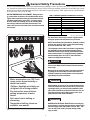
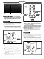
Non-Metallic Electric Water Heater USE & CARE MANUAL WITH INSTALLATION INSTRUCTIONS FOR THE INSTALLER Residential Electric Models 30 - 105 Gallon Capacity ■■■✦■■■ ■■■✦■■■ ■■■✦■■■ ■■■✦■■■ TM The purpose of this manual is twofold: one, for the installer, to provide requirements and recommendations for the proper installation and adjustment of the water heater; and two, for the owner-operator, to explain the features, operation, safety precautions, maintenance and trouble shooting of the water heater. This manual also includes a parts list supplement. It is imperative that all persons who are expected to install, maintain, operate or adjust this water heater read the instructions carefully so that they may understand how to do so. ! Recognize this symbol as an Indication of Important Safety Information! ! Do Not Destroy this Manual. Please read carefully and keep in a safe place for Future Reference. Table of Contents General Safety Precautions . . . . . . . . . . . . . . . . . . . . . . . . . . . . . . . . . . . . . . . . . . . . . . . . . . . . . . . . . . . . . . . . 1 Introduction . . . . . . . . . . . . . . . . . . . . . . . . . . . . . . . . . . . . . . . . . . . . . . . . . . . . . . . . . . . . . . . . . . . . . . . . . . . . . . . 2 Installation Instructions Thermal Expansion . . . . . . . . . . . . . . . . . . . . . . . . . . . . . . . . . . . . . . . . . . . . . . . . . . . . . . . . . . . . . . . . . . . . . . . . . 2 Water Supply Connections . . . . . . . . . . . . . . . . . . . . . . . . . . . . . . . . . . . . . . . . . . . . . . . . . . . . . . . . . . . . . . . . . . . 4 Temperature and Pressure Relief Valve . . . . . . . . . . . . . . . . . . . . . . . . . . . . . . . . . . . . . . . . . . . . . . . . . . . . . . . . . 4 Drain Valve . . . . . . . . . . . . . . . . . . . . . . . . . . . . . . . . . . . . . . . . . . . . . . . . . . . . . . . . . . . . . . . . . . . . . . . . . . . . . . . 4 Filling Water Heater . . . . . . . . . . . . . . . . . . . . . . . . . . . . . . . . . . . . . . . . . . . . . . . . . . . . . . . . . . . . . . . . . . . . . . . . 5 Electrical Connections . . . . . . . . . . . . . . . . . . . . . . . . . . . . . . . . . . . . . . . . . . . . . . . . . . . . . . . . . . . . . . . . . . . . . . . 5 Wiring Diagrams . . . . . . . . . . . . . . . . . . . . . . . . . . . . . . . . . . . . . . . . . . . . . . . . . . . . . . . . . . . . . . . . . . . . . . . . . . . 6 Pipe Wrap Energy Kit . . . . . . . . . . . . . . . . . . . . . . . . . . . . . . . . . . . . . . . . . . . . . . . . . . . . . . . . . . . . . . . . . . . . . . . 7 Installation Checklist . . . . . . . . . . . . . . . . . . . . . . . . . . . . . . . . . . . . . . . . . . . . . . . . . . . . . . . . . . . . . . . . . . . . . . . . 7 Operation Safety Precautions . . . . . . . . . . . . . . . . . . . . . . . . . . . . . . . . . . . . . . . . . . . . . . . . . . . . . . . . . . . . . . . . . . . . . . . . . 8 Thermal Performance . . . . . . . . . . . . . . . . . . . . . . . . . . . . . . . . . . . . . . . . . . . . . . . . . . . . . . . . . . . . . . . . . . . . . . . 8 Setting the Water Temperature . . . . . . . . . . . . . . . . . . . . . . . . . . . . . . . . . . . . . . . . . . . . . . . . . . . . . . . . . . . . . . . . 8 Safety Controls . . . . . . . . . . . . . . . . . . . . . . . . . . . . . . . . . . . . . . . . . . . . . . . . . . . . . . . . . . . . . . . . . . . . . . . . . . . . 10 Emergency Instructions . . . . . . . . . . . . . . . . . . . . . . . . . . . . . . . . . . . . . . . . . . . . . . . . . . . . . . . . . . . . . . . . . . . . . . 10 Vacation and Long Time Shut-Down . . . . . . . . . . . . . . . . . . . . . . . . . . . . . . . . . . . . . . . . . . . . . . . . . . . . . . . . . . . . 10 Draining the Water Heater . . . . . . . . . . . . . . . . . . . . . . . . . . . . . . . . . . . . . . . . . . . . . . . . . . . . . . . . . . . . . . . . . . . . 10 Maintenance Routine Preventive Maintenance . . . . . . . . . . . . . . . . . . . . . . . . . . . . . . . . . . . . . . . . . . . . . . . . . . . . . . . . . . . . . . 11 Temperature and Pressure Relief Valve . . . . . . . . . . . . . . . . . . . . . . . . . . . . . . . . . . . . . . . . . . . . . . . . . . . . . . . . . 11 Heating Elements . . . . . . . . . . . . . . . . . . . . . . . . . . . . . . . . . . . . . . . . . . . . . . . . . . . . . . . . . . . . . . . . . . . . . . . . . . 12 Trouble Shooting Guide . . . . . . . . . . . . . . . . . . . . . . . . . . . . . . . . . . . . . . . . . . . . . . . . . . . . . . . . . . . . . . . . . . . . 13 Wiring Schematic Diagrams . . . . . . . . . . . . . . . . . . . . . . . . . . . . . . . . . . . . . . . . . . . . . . . . . . . . . . . . . . . . . . . . 6 Warranty . . . . . . . . . . . . . . . . . . . . . . . . . . . . . . . . . . . . . . . . . . . . . . . . . . . . . . . . . . . . . . S e e S e p a r a t e S u p p l e m e n t Specifications . . . . . . . . . . . . . . . . . . . . . . . . . . . . . . . . . . . . . . . . . . . . . . . . . . . . . . . . . . See Separate Supplement Repair Parts . . . . . . . . . . . . . . . . . . . . . . . . . . . . . . . . . . . . . . . . . . . . . . . . . . . . . . . . . . . S e e S e p a r a t e S u p p l e m e n t Abbreviations found in this Instruction Manual U.L. — Underwriters Laboratories, 333 Pfingsten Rd., Northbrook, IL 60062 National Electrical Code — This publication is available from your local government, public library, electric company, or by writing to U.L. A.N.S.I. — American National Standards Institute A.S.M.E. — American Society of Mechanical Engineers. ! General Safety Precautions Be sure to read and understand the entire Use & Care Manual before attempting to install or operate this water heater. It may save you time and cost. Pay particular attention to the General Safety Precautions. Failure to follow these warnings could result in serious bodily injury or death. Should you have problems understanding the instructions in this manual, or have any questions, STOP, and get help from a qualified installer, service technician, or the local electric utility. WATER TEMPERATURE ADJUSTMENT - Safety and energy conservation are factors to be considered when selecting the water temperature setting of water heater’s thermostat. Water temperatures above 125°F. can cause severe burns or death from scalding. Be sure to read and follow the warnings outlined on the label pictured below. This label is also located on the water heater near the thermostat access panel TIME / TEMPERATURE RELATIONSHIPS IN SCALDS Temperature 120° F 125° F 130° F 135° F 140° F 145° F 150° F 155° F Time to Produce Serious Burn More than 5 minutes 11/2 to 2 minutes About 30 seconds About 10 seconds Less than 5 seconds Less than 3 seconds About 11/2 seconds About 1 second Table courtesy of Shriners Burn Institute ! DANGER The chart shown above may be used as a guide in determining the proper water temperature for your home. NOTE: Households with small children, disabled, or elderly persons may require a 120°F. or lower thermostat setting to prevent contact with “HOT” water. The temperature of the water in the heater is regulated by the adjustable surface mounted thermostat(s) located behind the Jacket Access Panel(s). Dual element heaters have two thermostats. To comply with safety regulations the thermostat(s) were set at 120° F. before the water heater was shipped from the factory. HOT ! DANGER There is a Hot Water SCALD Potential if the thermostat is set too high. Mixing valves for reducing point of use water temperature by mixing hot and cold water in branch water lines are available. Contact a licensed plumber or the local plumbing authority for further information. BURN Water temperature over 125°F can cause severe burns instantly or death from scalds. ! WARNING After installing, do not turn on or operate the water heater unless the temperature and pressure relief is in place and operating properly, you have properly installed the drain pipe on the temperature and pressure relief valve, the vacuum relief valve has been installed, and you have completely filled the water heater with water. Children, disabled and elderly are at highest risk of being scalded. See instruction manual before setting temperature at water heater. Feel water before bathing or showering. Temperature limiting valves are available, see manual. ! WARNING HAZARD OF ELECTRICAL SHOCK! Before removing any access panels or servicing the water heater, make sure the electrical supply to the water heater is turned ”OFF”. Failure to do this could result in property damage, bodily injury or death. 1 Introduction Thank you for buying your non-metallic electric water heater. Your new water heater is made of the latest materials and will not rust or corrode. It will give many years of hot water service when installed, operated and maintained according to the instructions in this manual. Your water heater is completely assembled and ready to install. This manual provides the general instructions for installation. Because of several variables, such as the installation location, existing piping, and local codes, it is impossible to provide exact instructions for everyone’s specific needs. For this reason, it is suggested that the entire manual be read prior to beginning any installation work, then carefully plan the installation. This can help to avoid costly mistakes including damage to the water heater, not covered under terms of the warranty. B A A — Diameter of water heater plus 2" min. B — Maximum 2" Almost all new products (automobiles, boats, clothing, plastic and wood items, etc.) have an odor or smell to them for a time. This water heater may also have a ”new” smell or odor to it due to the non-metallic materials used in the manufacturing process. This ”new” smell is not harmful, and will disappear in a short time. To open drain, line should be at least 3/4" ID and pitched for proper drainage. Figure 1. — Auxiliary Drain Pan ! CAUTION The water heater should not be located in an area where leakage of the tank or connections will result in damage to the area adjacent to it or to lower floors of the structure. Where such areas cannot be avoided, it is recommended that a suitable drain pan, adequately drained, be installed under the water heater. The vacuum valve, which must be used when installing the water heater, is factory installed. The location chosen for the water heater must take into consideration the following: LOCAL INSTALLATION REGULATIONS This water heater must be installed in accordance with these instructions, local codes, utility company requirements or, in the absence of local codes, the latest edition of the National Electrical Code. It is available from some local libraries or can be purchased from the National Fire Prevention Association, Batterymarch Park, Quincy, MA 02269 as booklet ANSI/NFPA 70. NOTE: Auxiliary drain pan installation MUST conform to local codes. Drain Pan Kits are available at your local retail outlet or service center. RESTAURANT INSTALLATION: If the water heater is to be installed in a restaurant, or other location where NSF International listing is required, it must be weather sealed to the floor, a raised base, or shelf so that seepage cannot accumulate under it; or elevated to provide at least (6) inches of clearance from the floor. LOCATION Locate the water heater in a clean dry area as near as practical to the area of greatest heated water demand. Long uninsulated hot water lines can waste energy and water. Place the water heater in such a manner that the thermostat and element access panels can be removed to permit inspection and servicing such as removal of elements or checking controls. The water heater and water lines should be protected from freezing temperatures. Do not install the water heater in outdoor, unprotected areas, or near any other appliances where high temperature are present, such as wood burning stoves, boilers or furnaces. High temperatures can warp or otherwise damage the non-metallic construction of this water heater. In order to meet NSF International requirements for Standard 5, the base of the water heater must be sealed to the floor to prevent seepage underneath. Apply a 3/8” bead of RTV Silicone completely around the floor edge of the base of the tank. Installation A ”closed water system”, however, prevents the expanding water from flowing back into the main supply line, and the result of ”thermal expansion” can create a rapid, and dangerous pressure increase in the water heater and system piping. This rapid pressure increase can quickly reach the safety setting of the relief valve, causing it to operate during each heating cycle. Thermal expansion, and the resulting rapid, and repeated expansion and contraction of components in the water heater and piping system can cause premature failure of the relief valve, and possibly the heater itself. Replacing the relief valve will not correct the problem! 1. INSPECT SHIPMENT — Inspect water heater for possible damage. Check the markings on the rating plate of the water heater to be certain the power supply corresponds to that for which the water heater is equipped. 2. THERMAL EXPANSION — Determine if a check valve exists in the inlet water line. It may have been installed in the cold water line as a separate back flow preventer, or it may be part of a pressure reducing valve, water meter or water softener. A check valve located in the cold water inlet line can cause what is referred to as a ”closed water system”. A cold water inlet line with no check valve or back flow prevention device is referred to as an ”open” water system. The suggested method of controlling thermal expansion is to install an expansion tank in the cold water line between the water heater and the check valve. The expansion tank is designed with an air cushion built in that compresses as the system pressure increases, thereby relieving the over pressure condition and eliminating the repeated operation of the relief valve. Other methods of controlling thermal expansion are also available. Contact your installing contractor, water supplier, or plumbing inspector for additional information regarding this subject. As water is heated, it expands in volume and creates an increase in the pressure within the water system. This action is referred to as ”thermal expansion”. In an ”open” water system, expanding water which exceeds the capacity of the water heater flows back into the city main where the pressure is easily dissipated. 2 Installation WATER HEATER INSTALLATION KIT Cold Water Inlet Hot Water Outlet Shut-Off Valve Hot Water Outlet Shut-Off Valve Cold Water Inlet 90° Elbow Flexible Connector Extension Fitting Flexible Connector Flexible Connector T&P Relief Valve * Vacuum Valve Ass’y Extension Fitting (included with heater) (included with heater) 90° Elbow T&P Relief Valve * Flexible Connector Vacuum Valve Ass’y (included with heater) (included with heater) Seal Ring Seal Ring Seal Ring (included with heater) HOT Outlet Hex Union Nut COLD Inlet Hex Union Nut (included with heater) HOT Outlet Hex Union Nut COLD Inlet Hex Union Nut SOLDERED COPPER OR CPVC PLASTIC PIPE Cold Water Inlet Hot Water Outlet Seal Ring (included with heater) (included with heater) Shut-Off Valve Hot Water Outlet Shut-Off Valve Cold Water Inlet 90° Elbow Union 3/4” Adaptor T&P Relief Valve * Union Union Union Sweat X Female Pipe 3/4” Adaptor 3/4” Adaptor Sweat x Male Pipe Sweat X Female Pipe Vacuum Valve Ass’y Extension Fitting T&P Relief Valve * Extension Fitting (included with heater) (included with heater) 90° Elbow Seal Ring Seal Ring (included with heater) Seal Ring Seal Ring (included with heater) (included with heater) COLD Inlet Hex Union Nut HOT Outlet Hex Union Nut HOT Outlet Hex Union Nut COLD Inlet Hex Union Nut Shut-Off Valve THREADED PIPE Cold Water Inlet Hot Water Outlet Vacuum Valve Ass’y (included with heater) (included with heater) (included with heater) 3/4” Adaptor Sweat x Male Pipe Hot Water Outlet Shut-Off Valve Cold Water Inlet 90° Elbow Union 90° Elbow Union Union Union 3/4” Female Coupling T&P Relief Valve * 3/4” Female Coupling Vacuum Valve Ass’y (included with heater) Extension Fitting Extension Fitting (included with heater) (included with heater) T&P Relief Valve * Vacuum Valve Ass’y (included with heater) Seal Ring Seal Ring Seal Ring Seal Ring (included with heater) (included with heater) (included with heater) (included with heater) HOT Outlet Hex Union Nut HOT Outlet Hex Union Nut COLD Inlet Hex Union Nut COLD Inlet Hex Union Nut CAUTION: DO NOT SWEAT SOLDER DIRECTLY TO THE WATER HEATER HEX UNION NUTS AS SOLDERING TORCH HEAT WILL DAMAGE THE WATER HEATER BEYOND REPAIR. * See Temperature & Pressure (T & P) Relief Valve section for drain pipe installation details. Figure 2 — Typical installation methods using Water Heater Installation Kit (top), Soldered Copper or CPVC Pipe (center), or Threaded Pipe (bottom). 3 Installation 3. WATER SUPPLY CONNECTIONS — Refer to Fig. 2 for suggested typical installation. The installation of unions or flexible copper connectors is recommended on the hot and cold water connections so that the water heater may be easily disconnected for servicing if necessary. The HOT and COLD water connections are clearly marked and are 3/4” NPT on all models. Install a shut-off valve in the cold water line near the water heater. 4. RELIEF VALVE — A relief valve is essential for safety and to protect the water heater. Too high of a temperature and/or pressure could cause the tank to burst. The relief valve is designed to automatically open if temperature and/or pressure reaches a pre-determined point (a temperature of 210°F, or pressure of 150 PSI) A new combination temperature and pressure relief valve, complying with the Standard for Relief Valves and Automatic Gas Shutoff Devices for Hot Water Supply Systems, ANSI Z21.22, has been factory installed in the opening provided and marked for the purpose on the water heater. (Refer to Figure 2) NOTE: If the incoming water pressure is over 80 PSI, be sure to install a pressure reducing valve (water pressure regulator) somewhere in the inlet water line upstream of the water heater. COLD WATER SUPPLY LINE TO HEATER — The cold water inlet has a factory installed vacuum relief valve in it. (Refer to Figure 2) Certain conditions, such as a break in the main water supply line, pump failure on a well system or other plumbing system malfunctions could produce a vacuum or negative pressure in the water heater’s tank. The vacuum relief valve provides a means to eliminate the negative pressure or vacuum in the event of such a failure by admitting air into the tank to equalize the pressure. ! WARNING DO NOT operate the water heater unless the Temperature and Pressure relief valve is installed properly and working correctly. Doing so will result in an unsafe operating condition that can result in property damage, bodily injury or death! NOTE: DO NOT remove the vacuum valve for any reason. Doing so will void the manufacturer’s warranty! Temperature & Pressure Relief Valve Run the cold water supply line to the top of the vacuum valve using the piping of choice for this installation as shown in Figure 2 Be sure to install a shut-off valve (not supplied with the heater) in the cold water line near the water heater. Support the relief valve drain pipe using metal strapping or wire fastened to the structure overhead Seal Ring Hex Union Nut (Relief Valve) IMPORTANT!! Do not apply heat directly to the vacuum valve connection. If sweat connections are used, sweat tubing to adapter before fitting adapter to vacuum valve on heater. Any heat applied to the vacuum relief valve and cold water fittings will permanently damage them and/or the tank. Union (The addition of a union at this point will help in the replacement of the T & P Relief Valve should the need arise.) The connection between the vacuum valve and the water heater uses a seal ring. If unions are not used on the water supply lines, the vacuum valve can be removed from the heater to accommodate final connection to supply piping. The hex union fitting on the water heater can then be used to make the connection between the tank and the valve/supply piping. Remember to use the seal ring provided with the heater when re-installing the vacuum valve and water inlet piping. DO NOT use pipe sealant on this joint! Drain Pipe No threads permitted on end of Drain Pipe. IMPORTANT! – DO NOT attempt to turn the pipe or fittings after the hex union nuts are tightened. Doing so will damage the water heater beyond repair! Drain Valve HOT WATER SUPPLY LINE FROM WATER HEATER— The hot water outlet has a factory installed extension fitting. Run the hot water supply line to the top of the extension fitting using the piping of choice for this installation as shown in Figure 2. 6” Maximum distance from drain pipe to suitable open drain. Figure 3 — Typical method of supporting relief valve drain pipe. DRAIN PIPE FROM RELIEF VALVE — Connect the outlet of the relief valve to a suitable open drain so that the discharge water cannot contact live electrical parts and to eliminate potential water damage (check Local Codes regarding Relief Valve discharge methods). Piping used should be of a type approved for hot water distribution. The discharge line must be no smaller than the outlet of the valve and must pitch downward from the valve to allow complete drainage (by gravity) of the relief valve and discharge line. The end of the discharge line should not be threaded or concealed and should be protected from freezing. No valve of any type, restriction or reducer coupling should be installed in the discharge line. IMPORTANT! – Do not apply heat directly to the extension fitting. If sweat connections are used, sweat tubing to adapter before fitting adapter to extension fitting on heater. Any heat applied to the extension fitting and hot water fittings will permanently damage them and/or the tank. The connection between the extension fitting and the water heater uses a seal ring. If unions are not used on the water supply lines, the extension fitting can be removed from the heater to accommodate final connection to hot water supply piping. The hex union fitting on the water heater can then be used to make the connection between the tank and the piping system. Remember to use the seal ring provided with the heater when re-installing the vacuum relief valve and water inlet piping. DO NOT use pipe sealant on this joint! Following all of the above rules, install the drain valve discharge piping, using thread sealer on all male threads. IMPORTANT!! Do not apply heat directly to the relief valve connection. If sweat connections are used, sweat tubing to adapter before fitting adapter to relief valve on heater. Any heat applied to the relief valve will permanently damage it and/or the tank. IMPORTANT! – DO NOT attempt to turn the pipe or extension piece after the hex union nuts are tightened. Doing so will damage the water heater beyond repair! 4 Installation To prevent stress on the relief valve fitting, which may damage the tank, support the drain pipe using metal strapping or similar method to an overhead point. Refer to Figure 3 for typical strapping method. Metallic Conduit or Metal Sheathed Cable and fittings approved for use as a grounding conductor. NOTE: Local codes shall govern the installation of relief valves. If the Temperature and Pressure Relief Valve should ever need replacing, use only a valve specified by local codes, but not less than a new combination temperature and pressure relief valve, complying with the Standard for Relief Valves and Automatic Gas Shutoff Devices for Hot Water Supply Systems, ANSI Z21.22. The pressure rating of the relief valve must not exceed 150 PSI, the maximum working pressure of the water heater as marked on the rating plate. The BTUH Rating of the relief valve must not be less than the input rating of the water heater as indicated on the rating label located on front of the heater (1 watt = 3.412 BTUH). BLACK Main Fuse or Circuit Breaker Panel RED GREEN 5. DRAIN VALVE — The drain valve is factory installed. If required, to face the drain valve outlet in a different direction, loosen the union hex nut, position drain valve outlet as desired, and retighten union hex nut. Wire Nut Wire Nut NOTE: DO NOT attempt to turn the drain valve without first loosening the union hex nut. Doing so could damage the water heater beyond repair. BLACK RED 6. TO FILL WATER HEATER — Make certain drain valve is completely closed. Open shut-off valve in cold water supply line. Open each hot water faucet slowly to allow air to vent from the water heater and piping. A steady flow of water from the hot water faucet(s) indicates a full water heater. When the water heater is completely filled, close the faucet(s). Check all plumbing work for leaks, and repair as necessary before proceeding with installation. Water Heater Junction Box Figure 5A— Water heater field wiring connections using metallic conduit or metallic sheathed cable approved for use as a grounding conductor and installed with fittings approved for the purpose. ! WARNING Tank MUST BE full of water before power is turned on. Heating elements WlLL BE DAMAGED if energized for even a short time while tank is dry. The water heater’s warranty does not cover damage or failure resulting from operation with an empty or partially empty tank. (Reference is made to the limited warranty for complete terms and conditions.) Non - Metallic Sheathed Cable with separate grounding conductor. Junction Box Cover Main Fuse or Circuit Breaker Panel Grounding Conductor (Bare or Green) BLACK RED GREEN Wire Nut Wire Nut BLACK RED Figure 4 — Water heater junction box location. Water Heater Junction Box 7. ELECTRICAL CONNECTIONS — The water heater is completely wired to the junction box inside jacket at top front of water heater (see Figure 4). An opening for a l/2” or 3/4” electrical fitting is provided for field wiring connections. A separate branch circuit with copper conductors, overcurrent protective device and suitable disconnecting means must be provided by a qualified electrician. The voltage requirements and wattage load for the water heater is specified on the rating plate on front of heater. Be certain that the Figure 5B— Water heater field wiring connections using nonmetallic sheathed cable and separate grounding conductor. Grounding conductor must be attached to the ground terminal of water heater and the electrical distribution panel. 5 Installation local codes, the latest edition of National Electrical Code ANSI/NFPA 70. The complete wiring schematic diagram for standard nonsimultaneous operation units is shown below in Figure 6. The Specification Table (supplied separately with the water heater) recommends minimum branch circuit sizing based on National Electric Code. High Limit Switch 1 Upper Temperature Control Thermostat RED The branch circuit wiring must include either: RED BLACK Water Heater Junction Box BLACK GROUND From 240 V Power Source 3 2 4 1 4 Metallic conduit or metallic sheathed cable approved for use as a grounding conductor and installed with fittings approved for the purpose. (refer to Figure 5A) B. Non-metallic sheathed cable or metallic conduit or metallic sheathed cable not approved for use as a ground conductor shall include a separate conductor for grounding. It should be attached to the ground terminals of the water heater and the electrical distribution box. (Refer to Fig. 5B) Be sure to follow local and national codes as well as any electric utility requirements when making the connections. BLUE YELLOW 2 CONNECTING THE WATER HEATER TO A TIME SWITCH OR OFFPEAK METER — In some installations it may be desired or required by local utility regulations to connect the water heater to a Time Switch or OffPeak Meter. Refer to Figure 7 or 8 below for complete wiring schematic diagram for standard non-simultaneous operation units installed in conjunction with these energy management devices. BLACK Upper Element Lower Temperature Control Thermostat A. ! WARNING RED 1 YELLOW 2 Connecting the water heater to a Time Switch or Off-Peak Meter requires splicing or complete replacement of internal wiring. For this reason, it is strongly recommended that this work be performed by a licensed electrician, qualified appliance service person, or utility company representative. Lower Element Figure 6— Complete Schematic Diagram —Standard power supply provided isWiring equivalent to that marked on the water heater’s Non-Simultaneous Operation. rating plate. All wiring must conform to local codes or, in the absence of IMPORTANT!! — When connecting the water heater to a Time Switch or Off-Peak Meter, the Black wire from Terminal No. 4 of the From 240 V Power Source From 240 V Power Source From Off Peak Meter 1 3 2 4 1 4 4 1 4 BLACK YELLOW BLUE BLACK YELLOW Upper Element Lower Temperature Control Thermostat RED Lower Temperature Control Thermostat 3 2 2 2 Upper Element RED BLACK 1 Upper Temperature Control Thermostat BLUE Upper Temperature Control Thermostat RED BLACK High Limit Switch RED High Limit Switch BLACK GROUND Water Heater Junction Box RED GROUND BLACK From Time Clock Switch Water Heater Junction Box 1 1 2 YELLOW YELLOW 2 Lower Element Lower Element Figure 7 — Complete Wiring Schematic Diagram — Non-Simultaneous Operation on separate Time Switch. Figure 8 — 6 Complete Wiring Schematic Diagram — Non-Simultaneous Operation on separate Off-Peak Meter. Installation 8. PIPE WRAP ENERGY KIT — A pipe wrap energy saving kit consisting of two lengths of foam insulation is included with this water heater. To realize maximum energy savings, all exposed pipes should be insulated. However, most of the energy losses occur close to the water heater. This kit is designed to minimize this loss. Install one piece of insulation on the cold water supply line and the other piece on the hot water line. (Refer to Figure 9). Install the pipe wrap as close to the water heater as the installation allows. Make sure fittings are covered and the joint in the pipe wrap is sealed. Pipe Wrap Energy Kit. (Seal Tightly) NOTE! Do Not Cover or Block This Opening on Vacuum Valve The water heater tank is insulated with 2 1/2” of foam insulation to stop heat loss. More insulation is not needed. DO NOT install an insulating blanket. ! CAUTION If local codes require external application of insulation blanket kits the manufacturer’s instructions included with the kit must be carefully followed. Figure 9 — Pipe Wrap Energy Kit Limit Switch must be disconnected and replaced totally, or disconnected and joined with a new section of wire using a proper connector. Be sure to follow all local and national codes and electric utility requirements when making the connections. Application of any external insulation to this water heater will require careful attention to the following: Dual element water heaters are designed to allow only one element to heat at a time. This method is called non-simultaneous operation and is necessary to avoid overloading the wiring in the house per the National Electrical Code. Off-Peak wiring methods must insure proper use of the high limit control in at least one line to each element and the use of the non-simultaneous feature. • • Do not cover the temperature and pressure relief valve. • • Do not cover electrical junction box of water heater. Do not cover jacket access panels to thermostats and heating elements. Do not cover operating or warning labels attached to the water heater nor attempt to relocate them on exterior of insulation blanket. ! WARNING ! CAUTION The manufacturer’s warranty does not cover any damage or defect caused by installation, attachment or use of any type of energy saving or other unapproved devices (other than those authorized by the manufacturer) into, onto or in conjunction with the water heater. The use of unauthorized energy saving devices may shorten the life of the water heater and may endanger life and property. The manufacturer disclaims any responsibility for such loss or injury resulting from the use of such unauthorized devices. Tank MUST BE full of water before power is turned on. Heating elements WlLL BE DAMAGED if energized for even a short time while tank is dry. The water heater’s warranty does not cover damage or failure resulting from operation with an empty or partially empty tank. (Refer to the limited warranty for complete terms and conditions.) Installation Check List A. Water Heater Location C. Relief Valve Close to area of heated water demand. Indoors and protected from freezing temperatures. Area free of flammable vapors. Provisions made to protect area from water damage. Sufficient room to service water heater. Temperature and Pressure Relief Valve properly installed and discharge line run to open drain. Discharge line protected from freezing. D. Wiring Power supply voltage agrees with water heater rating plate. Branch circuit wire and fusing or circuit breaker of prop- B. Water Supply er size. Water heater completely filled with water. Water heater and piping air vented. Water connections tight and free of leaks. Model No. Electrical connections tight and unit properly grounded. Serial No. Date of Installation 7 Installed By: Operation SAFETY PRECAUTIONS A. Do turn off power to water heater if it has been subjected to over heating, fire, flood or physical damage. B. Do Not turn on water heater unless it is completely filled with water. C. Do Not turn on water heater if cold water supply shut-off valve is closed. D. If there is any difficulty in understanding or following the OPERATION or MAINTENANCE instructions, it is recommended that a qualified person or serviceman perform the work. ! CAUTION NEVER use this water heater unless it is completely full of water. To prevent damage to the tank and heating elements the tank must be filled with water. Water must flow from the hot water faucet(s) before turning power ”ON” 1. WATER TEMPERATURE SETTING AND THERMAL PERFORMANCE Water heaters see a wide range of applications. Some of the most challenging are those involved in thermal storage, tempering valves or large volumes of heated water used for cleaning and sanitizing. One other reminder is to be sure that the T & P Valve is properly installed. It is a plumbing code requirement in most parts of the country to plumb the T & P Valve to discharge within six inches of the floor. This is clearly described in the Installation section of this manual. Failure to do this is not only a violation of the plumbing code, but a safety hazard for anyone near the water heater in the event the T & P discharges. Not having the T & P plumbed with a drain line also allows water to be potentially discharged onto the top of the water heater if the valve opens. The consequence of this could be inaccurate temperature sensing by the thermostats, if they are cooled by the discharged water as it evaporates. Another negative result could be saturated insulation, which would waste energy, be the source of a high bill complaint and reduce the insulation’s ability to support the tank. Achieving satisfactory service from a water heater in these applications is critical. The solution is found in understanding the operation of the typical water heater. In a dual element water heater, the upper thermostat is given priority and will operate first when the tank is completely cold. By operating first, a small amount of hot water is available quickly. When the upper thermostat is satisfied, the electrical current is switched to the lower thermostat. As the lower element begins to heat the water above it, energy (heat) is also being put into the water at the very top of the tank. If the upper thermostat is set at, or very near its upper limit, the temperature at the top of the tank can possibly be elevated to the point of tripping the T & P valve or the Thermal Cut-Out on the upper thermostat. In either case, the mechanisms sense temperatures beyond the predetermined limit and activate to lower the temperature. In other words, they do their job. In conclusion, non-metallic water heaters are designed and built to provide years of service. Having them properly installed and accurately adjusted is essential if they are to perform reliably in the many challenging applications in which they are installed. 2. WATER TEMPERATURE SETTING — To comply with safety regulations the thermostats are factory set at 120° F. or less where local codes require, and is usually sufficient for most household needs. Reliable performance can be achieved in most applications if the upper thermostat is left at the factory set temperature of 120°F. During heavy water usage, the upper thermostat will provide a limited amount of hot water quickly. The temperature of this water at the factory set temperature will satisfy most household needs. After the upper thermostat is satisfied, the lower thermostat will then heat all of the water in the tank to it desired setting. This temperature setting method will not increase the total heating time or reduce the final temperature of the water in the tank. For normal applications it is recommended that the upper thermostat be left at the factory set temperature of 120°F and all water temperature adjustments be made at the lower thermostat only. Maximum water temperatures occur just after the elements have shut off. To find out exact temperature of the water being delivered, turn on a hot water faucet and allow it to run until maximum temperature is reached, then insert a thermometer in the water stream and read the temperature. Safety and energy conservation are factors to be considered when selecting the water temperature setting of the water heater’s thermostats . The lower the temperature setting the greater the safety and savings in energy and operating costs. If a different temperature setting is desired, read and follow the following warnings and instructions. If an application requires adjustment of the upper thermostat, it can be adjusted by following the instructions in the ”Resetting the Thermostat” section later in this manual. To achieve the most consistent operation, have the upper thermostat adjusted 10 to 15 degrees below the setting of the lower thermostat. This will reduce the ”stacking” effect inside the water heater, but will still allow the water heater to produce water at the desired temperature. ! DANGER There is a Hot Water SCALD Potential if the thermostat is set too high. NOTE: Households with small children or invalids may require a 120° F. or lower thermostat setting to prevent contact with “HOT” water. Caution is important in installations where very high water temperatures are needed for a required application. Water at high temperatures can quickly cause severe scalding, especially in children or elderly people. It is strongly recommended that great care be taken to prevent scalding. A tempering valve must be used in any area used for washing or bathing, and where access is available to the elderly or children. We also recommend that the thermostats be set at the lowest possible setting to meet the application. Please refer Thermostat Setting section of this manual for additional information and recommendations. Mixing valves for reducing point of use water temperature by mixing hot and cold water in branch water lines are available. Contact a licensed plumber of the local plumbing authority for further information. The following chart may be used as a guide in determining the proper water temperature for your home. 8 Operation TIME / TEMPERATURE RELATIONSHIPS IN SCALDS Temperature 120° F 125° F 130° F 135° F 140° F 145° F 150° F 155° F Time to Produce Serious Burn More than 5 minutes 11/2 to 2 minutes About 30 seconds About 10 seconds Less than 5 seconds Less than 3 seconds About 11/2 seconds About 1 second Reset Button Temperature Adjustment Screw (Shown at Factory Setting of approx. 120° F.) Table courtesy of Shriners Burn Institute HI setting equals approximately 170° F water temperature. RESETTING THE UPPER THERMOSTAT — It is recommended that the upper thermostat remain at the factory setting for most normal applications. All water temperature adjustments should be made at the lower thermostat. If your application requires adjustment of the upper thermostat, it can be changed as follows: LOW HI LOW setting equals approximately 110° F water temperature. MED MED setting equals approximately 140° F water temperature. ! DANGER Figure 11 — Upper Thermostat temperature adjustment. Make certain power to water heater is OFF before removing jacket access panel(s) FOR ANY REASON. Failure to do so could result in property damage, bodily injury or death! E. Replace the single piece of fiberglass insulation inside the thermostat access panel cover and snap in position. NOTE: It is important that the fiberglass insulation is replaced to maintain the water heater’s high energy efficiency performance. A. Remove the upper thermostat snap-in access panel cover. Insert finger into latch hole on the bottom of the cover, and push up to release the latch. Then pull forward to remove the cover and insulation. (See figure 10.) RESETTING THE LOWER THERMOSTAT — It is recommended that any water temperature adjustment be made at the lower thermostat only. If your application requires adjustment of the lower thermostat, it can be changed as follows: ! DANGER Thermostat Insulation (2) Make certain power to water heater is OFF before removing jacket access panel(s) FOR ANY REASON. Failure to do so could result in property damage, bodily injury or death! Access Panel Cover A. Remove the lower thermostat snap-in access panel cover. Insert finger into latch hole on the bottom of the cover, and push up to release the latch. Then pull forward to remove the cover and insulation. (See Figure 12.) Upper Thermostat Access Panel Cover Cover Insulation Thermostat Access Panel Thermostat Insulation (2) Latch Hole Access Panel Cover Figure 10 — Removing Upper Thermostat Access panel. B. Remove the four (4) screws securing the thermostat access panel and the two (2) thermostat insulation pads, exposing the thermostat. The plastic personnel protector should not be removed. Lower Thermostat Access Panel Cover C. With a small screwdriver, adjust the thermostat setting. This thermostat is marked LOW / MED / HI. The 120°F factory set position (the recommended setting) is at the 5 o’clock position (Refer to Figure 11). The temperature settings range from approximately 110°F (LOW) to approximately 170°F (HI). The MED position results in approximate water temperature of 140° F. Cover Insulation Thermostat Access Panel Latch Hole D. Replace the two (2) pieces of fiberglass insulation over the thermostat and attach the thermostat access panel. Figure 12 — Removing Lower Thermostat Access panel. 9 Operation ! CAUTION B. Remove the four (4) screws securing the thermostat access panel and the two (2) thermostat insulation pads, exposing the thermostat. The plastic personnel protector should not be removed. The cause of the High Temperature Condition must be investigated by qualified service personnel and corrective action taken before placing the water heater in service again. C. With a small screwdriver, adjust the thermostat setting. This thermostat is marked in degrees from 110°F to 170°F. The thermostat is factory set to the 120°F position (the recommended setting). (Refer to Figure 13). To reset High Limit Switch, turn off power to water heater, remove upper jacket access panel and insulation, and the access panel and insulation to expose the Thermostat and High Limit Switch. (Refer to Figure 10.) The plastic personnel protesctor SHOULD NOT be removed. Press the “RESET” button (see Figure 14). Replace insulation and jacket access panel(s) before turning on power to water heater. 4. EMERGENCY INSTRUCTIONS — Temperature Adjustment Screw (Shown at Factory Setting of approx. 120° F.) 170 ! WARNING If water heater has been subjected to flood, fire, or physical damage, turn off power and water to water heater. Do not operate the water heater again until it has been thoroughly checked by qualified service personnel. 110 120 160 150 140 130 5. VACATION AND LONG TIME SHUT-DOWN — If the water heater is to remain idle for an extended period of time, the power and water to the water heater should be turned off to conserve energy. The water heater and piping should be drained if they might be subjected to freezing temperatures. Figure 13 — Lower Thermostat temperature adjustment. After a very long shut-down period, the water heater’s operation and controls should be checked by qualified service personnel. Make certain the water heater is completely filled before again placing it in operation . D. Replace the two (2) pieces of fiberglass insulation over the thermostat and attach the thermostat access panel. E. Replace the single piece of fiberglass insulation inside the thermostat access panel cover and snap in position. 6. DRAINING THE WATER HEATER — ! CAUTION NOTE: It is important that the fiberglass insulation is replaced to maintain the water heater’s high energy efficiency performance. Always shut off power to water heater before draining water. 3. SAFETY CONTROLS — The water heater is equipped with a combination Thermostat and High Temperature Limit Switch that is located above the upper heating element. If for any reason the water temperature becomes excessively high, the Limit Switch breaks the power circuit to the heating element. Once the control opens, it must be reset manually. In order to drain water heater, turn off the power supply, then turn off cold water supply. Next, it is necessary to open a hot water faucet or lift the handle on the relief valve to admit air to the tank, and KEEP OPEN. Attach a garden hose to the drain valve on the water heater, and open the valve. Direct the stream of water to a drain where it will do no damage. (See Figure 15). Limit Switch (Located at Upper Element on Double Element Models) ! DANGER The water drained from the tank may be hot enough to present a SCALD HAZARD and should be directed to a suitable drain to prevent injury or damage. Reset Button Temperature Adjustment Screw (Shown at Factory Setting of approx. 120° F.) Drain Valve Temperature Control Thermostat Floor Drain (or other suitable drain) Garden Hose Figure 14 — Upper Thermostat & High Limit Switch Figure 15 — Draining the Tank 10 Maintenance hammer” can be described as a banging noise heard in a water pipe following an abrupt alteration of the flow with resulting pressure surges. Strategically located risers in the water pipe system can be used to minimize the problem. Also water hammer arresting devices are usually available from your plumber or local plumbing supply store. Properly maintained, your new, non-metallic water heater will provide years of dependable trouble-free service. It is suggested that a routine preventive maintenance program be established and followed by the user. It is further recommended that a periodic inspection of the operating controls, heating element and wiring should be made by service personnel qualified in electric appliance repair. 2. REPLACING THE TEMPERATURE & PRESSURE RELIEF VALVE — 1. ROUTINE PREVENTATIVE MAINTENANCE If the Temperature and Pressure Relief Valve should ever need replacing, use only a valve specified by local codes, but not less than a new combination temperature and pressure relief valve, complying with the Standard for Relief Valves and Automatic Gas Shutoff Devices for Hot Water Supply Systems, ANSI Z21.22. The pressure rating of the relief valve must not exceed 150 PSI, the maximum working pressure of the water heater as marked on the rating plate. The BTUH Rating of the relief valve must not be less than the input rating of the water heater as indicated on the rating label located on front of the heater (1 watt = 3.412 BTUH). A. Most electrical appliances make some sound when in operation, even when new. If the hissing or singing sound level increases excessively, the electric heating element may require cleaning. Contact your installer or plumbing contractor to inspect. B. The area near the water heater must be kept free of flammable liquids such as gasoline or paint thinners, adhesives or other combustible materials. ! CAUTION C. At least once a year, lift and release the lever handle on the temperature pressure relief valve, located on top of the water heater, to make certain the valve operates freely and allow several gallons to flush through discharge line (see Figure 16). Make certain the discharged water is directed to an open drain. Before starting to replace the Temperature & Pressure Relief Valve, be sure to turn the power supply to the water heater ”OFF” at the electrical distribution panel. A. With the power supply turned ”OFF”, close the shut-off valve installed in the cold water supply pipe. Lift and release lever on T&P Valve several times to be sure that it opens and operates freely. Allow several gallons of water to flush through the discharge pipe Temperature & Pressure Relief Valve B. Open a nearby hot water faucet and KEEP OPEN. C. Fasten a length of garden hose to the drain valve. Place the other end of the hose at a floor drain, or other suitable location. (See FIgure 15) Support Strap D. Open the drain valve for about a minute or until the water level in the tank is below the relief valve. Discharge Pipe ! DANGER The water drained from the tank may be hot enough to present a SCALD HAZARD and should be directed to a suitable drain to prevent injury or damage. E. Remove the discharge pipe from the relief valve, then remove the old relief valve (see Figure 3 on pg. 4). Use two wrenches, one to hold the union hex nut on the heater, and one to remove the relief valve. NEVER use just one wrench! Doing so can damage the tank beyond repair. Figure 16 — Manually Operating the Temperature and Pressure Relief Valve ! DANGER F. Be sure a seal ring is inside the center (relief valve) union hex nut. Use factory seal washers only. DO NOT use sealants with seal ring washers! Next, turn the valve into the union fitting on the tank. Face the relief valve outlet in a direction of the old valve. Hold the valve in place and tighten the union hex nut. Before manually operating the relief valve, make certain no one will be exposed to the danger of coming in contact with the hot water released by this valve. The water may be hot enough to create a SCALD hazard. The water released should be directed to a suitable drain to prevent injury or damage. IMPORTANT!! Do not apply heat directly to the relief valve connection. If sweat connections are used, sweat tubing to adapter before fitting adapter to relief valve on heater. Any heat applied to the relief valve will permanently damage it and/or the tank. NOTE: If the temperature and pressure relief valve on the water heater discharges periodically, this may be due to thermal expansion in a “Closed” water system. Contact the water supplier or your plumbing contractor on how to correct this. DO NOT plug the relief valve outlet. G. Install the discharge pipe to the new relief valve. (see Figure 3 on pg. 4). H. Open the cold water supply shut-off valve. When water from hot water faucet opened earlier runs smooth, with no more air bubbles, close the faucet. D. A water heater’s tank can act as a settling basin for solids (sand, silt, dirt and mineral scale) suspended in the water. It is, therefore, not uncommon for these deposits to accumulate in the bottom of the tank. It is suggested that a few quarts of water be drained from the water heater’s tank ONCE EVERY MONTH to clean the tank of these deposits. (See Figure 15) I. Turn the electric power on to place the water heater in service again. ! CAUTION Be sure the water heater is completely filled with water before turning on electric power. E. Rapid closing of faucets or solenoid valves in automatic water using appliances can cause a pounding “water hammer” sound. “Water 11 Maintenance G. To expose the element for removal, lift up the hinged portion of the thermostat protective cover by gently pulling the lower corners up and away from the thermostat. Be careful to avoid pulling the thermostat from its mounting bracket, or bending the thermostat bracket. 3. HEATING ELEMENTS — Most water supplies will cause scale or mineral deposits to form on the heating elements. As the scale forms, it gets increasingly harder for the element to heat water. If you hear a rumbling noise coming from the water heater, it is probably caused by scale build up on the elements. Element life can be lengthened by installing a water softener or other water treating equipment that removes most of the minerals that cause scale. H. After again insuring that the electrical power is off, disconnect the two wires from the element terminals. (See Figure 18). TO REPLACE BURNED OUT ELEMENTS — IMPORTANT! — The elements used in the lower element position are different than those in the upper position. It is important to note that STANDARD REPLACEMENT ELEMENTS WILL NOT FIT THIS WATER HEATER! Proper replacement elements are available at your local retail outlet or service center. Be sure to refer to parts illustration supplied with the heater for proper identification of replacement elements. Care must be taken to insure that the correct element is being used. The tank warranty may be voided if the wrong element is used. Yellow Wire Blue Wire Wiring Terminals Heating Element (1-7/8” Hex.) ! CAUTION Before starting to remove an Element, be sure to turn the power supply to the water heater ”OFF” at the electrical distribution panel. I. With wires removed from the element terminals, remove the old element by turning it counterclockwise (4) using a 17/8” wrench or socket. A. With the power supply turned ”OFF”, close the shut-off valve installed in the cold water supply pipe. J. With a new gasket in place, install and tighten the new element. B. Open a nearby hot water faucet and KEEP OPEN. NOTE: Be sure the gasket sealing surface is clean. Wet the new gasket with water to lubricate and make a good seal. C. Fasten a length of garden hose to the drain valve. Place the other end of the hose at a floor drain, or other suitable location. (See FIg. 15 ) K. Close the water heater drain valve and completely fill tank with water. Check the element for leaks. Repairs any leaks as needed. D. Open the drain valve and drain the heater until the water level in the tank is below the element needing replacement. L. Reconnect wiring to the terminals on the element (see FIgure 18). ! DANGER ! WARNING The water drained from the tank may be hot enough to present a SCALD HAZARD and should be directed to a suitable drain to prevent injury or damage. Failure to properly tighten element terminal screws can cause a fire which can result in property damage, bodily injury or death. M. Lower the hinged portion of the thermostat protective cover to cover the element and its wiring connections. E. Close the drain valve and remove the hose. F. Remove the thermostat snap-in access panel cover. Insert finger into latch hole on the bottom of the cover, and push up to release the latch. Then pull forward to remove the cover and insulation. Remove the four (4) screws securing the thermostat access panel and the two (2) thermostat insulation pads, exposing the thermostat. (See Figure 17.) ! WARNING Make sure the thermostat is flush against the thermostat mounting plate, and the protective cover is in place before replacing the insulation pads and access cover. Failure to do so can result in property damage, bodily injury or death. N. Replace the two pieces of fiberglass insulation over the thermostat and attach the thermostat access panel. Replace the single piece of insulation in the thermostat access panel cover and snap it into position. Thermostat Insulation (2) Access Panel Cover O. Turn on the electrical power supply to bring the heater into service again. Upper or Lower Thermostat Access Panel Cover ! WARNING Tank MUST BE full of water before power is turned on. Heating element(s) WlLL BE DAMAGED if energized for even a short time while tank is dry. The water heater’s warranty does not cover damage or failure resulting from operation with an empty or partially empty tank. (Reference is made to the limited warranty for complete terms and conditions.) Cover Insulation Access Panel Latch Hole Figure 17 — Removing Access panel for replacement of element. 12 Maintenance 4. VACATION AND LONG TIME SHUTDOWN — If the water heater is installed where it could freeze (summer cabin, lake home, etc.) you must drain all water from it and the piping. If the tank is full of water and it freezes, the tank will break. Freeze damage is not covered by the warranty! ! DANGER The water drained from the tank may be hot enough to present a SCALD HAZARD and should be directed to a suitable drain to prevent injury or damage. When preparing to place the water heater in service again, be sure to completely fill the tank with water before turning the power on. DRAINING THE WATER HEATER — ! CAUTION Always shut off power to water heater before draining water. In order to drain water heater, turn off the power supply, then turn off cold water supply. Next, it is necessary to open a hot water faucet or lift the handle on the relief valve to admit air to the tank, and KEEP OPEN. Attach a garden hose to the drain valve on the water heater, and open the valve. Direct the stream of water to a drain where it will do no damage. (See Figure 19). ! CAUTION Tank MUST BE full of water before power is turned on. Heating element(s) WlLL BE DAMAGED if energized for even a short time while tank is dry. The water heater’s warranty does not cover damage or failure resulting from operation with an empty or partially empty tank. (Reference is made to the limited warranty for complete terms and conditions.) After a very long shut-down period, the water heater’s operation and controls should should be checked by a qualified service technician. Drain Valve Floor Drain (or other suitable drain) ! WARNING If water heater has been subjected to flood, fire, or physical damage, turn off power and water to water heater. Do not operate the water heater again until it has been thoroughly checked by qualified service personnel. Garden Hose Figure 19 — Draining the Tank Trouble Shooting Guide NATURE OF TROUBLE No Hot Water POSSIBLE CAUSE SERVICE 1. Manual disconnect switch turned off 2. Improper Wiring 3. No Power — blown fuse or circuit breaker tripped a. Shorted wiring b. Circuit overloaded c. Improper wiring d. Grounded element or thermostat 4. Manual Reset High Limit Switch (ECO) open a. Thermostat(s) defective b. Thermostat out of calibration c. Heat build-up due to loose wires d. Defective High Limit Switch (ECO) Turn to ON ** Rewire per Wiring Diagram Replace fuse or reset breaker ** Replace or repair ** Provide adequate circuit or reduce load ** Rewire per diagram ** Replace Refer to "Operation Section" ** Replace ** Lower setting or replace ** Tighten wire connections ** Replace Not enough Hot Water 1. Heater undersized 2. Defective Element(s) 3. Miswired or defective thermostat causing only one element to work Reduce rate of hot water use ** Check amperage, replace element if low ** Check wiring or replace Water too hot or not hot enough 1. Thermostat setting too high or low 2. Thermostat out of calibration Change setting as required ** Replace (continued) ! CAUTION ** For your safety, DO NOT attempt repair of Electrical Wiring, Thermostat(s), Heating Elements or other Operating Controls. Refer repairs to qualified personnel. 13 service Trouble Shooting Guide (cont’d) NATURE OF TROUBLE POSSIBLE CAUSE SERVICE Water too hot or not hot enough (cont’d) 3. Thermostat access panel(s) and/or insulation not in place 4. Thermostat(s) not resting tightly against mounting plate Noisy heating element(s) 1. Scale build-up on elements Water Leaks 1. Loose connection between inlet/outlet piping, relief valve or drain valve and hex nut union on tank fittings. 2. Damaged seal ring washer. 3. Gasket around heating element(s) Inspect and replace as needed Inspect and insure that retaining spring(s) or mounting screws hold thermostat(s) tightly to mouting plates. ** Remove and clean Tighten hex nut union fitting. Replace seal rings as required Inspect and replace gasket if needed. ! CAUTION ** For your safety, DO NOT attempt repair of Electrical Wiring, Thermostat(s), Heating Elements or other Operating Controls. Refer repairs to qualified personnel. ! NOTICE service ! FOR INSTALLATIONS IN THE STATE OF CALIFORNIA California Law requires that residential water heaters must be braced, anchored or strapped to resist falling or horizontal displacement due to earthquake motions. For residential water heaters up to 52 gallon capacity, a brochure with generic earthquake bracing instructions can be obtained from: OFFICE OF THE STATE ARCHITECT 400 P Street Sacramento, CA 95814 Telephone: (916)324-5315 or, ask a water heater dealer. However, applicable Local Codes shall govern installations. (For residential water heaters of capacity greater than 52 gallons, consult the local building jurisdiction for acceptable bracing installations) ! CALIFORNIA PROPOSITION 65 WARNING: This product contains chemicals known to the State of California to cause cancer, birth defects or other reproductive harm. Water Heater Innovations, Inc. 3107 Sibley Memorial Highway Eagan, Minnesota 55121 Phone (651)688-8827 FAX (651)688-6615 A Printed in USA Subsidiary SP213270 (04/04)