1
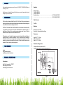
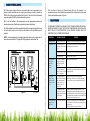
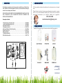
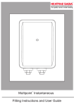
Congratulations!
You've just purchased a new Santon tankless water heater and will
soon begin to enjoy the benefits of “going tankless.”
Take the time to thoroughly read and understand this safety and
installation manual in its entirety before you attempt to install your new
Santon tankless water heater, as it contains important safety tips and
instructions.
Please carefully read all instructions and warnings. If you need
assistance or have any questions please contact us at:
1-512-332-2229
Please keep this manual for future reference.
02
WARNING
04
INTRODUCTION
04
PACK CONTENTS
04
TECHNICAL SPECIFICATIONS
04
INTERNAL COMPONENTS
06
SAFETY
07
SITE REQUIREMENTS
07
CONNECTING TO SERVICES
10
COMMISSIONED
11
MULTIPLE INSTALLATIONS
12
FAULT FINDING
13
SPARE PARTS
14
CUSTOMER SERVICE
15
OTHER PRODUCTS
15
03
If your water heater requires a reset, be sure to TURN OFF THE BREAKER prior to
resetting the unit.
Resetting your unit without turning off the breaker can result in personal injury and
damage to your water heater.
Electrical:
Model numbers
7.0kW - 94 805 005
9.0kW - 94 805 006
Electrical rating................................................................. 6.4/7.0kW @ 230/240V
..........................................................................................8.3/9.0kW @ 230/240V
Rated Pressure:
Thank you for purchasing a Marey Power Pack. The Power Pack unvented pressure
system water heater is manufactured to the highest standards and has been designed
tomeetallthelatestrelevantsafetyspecifications.
7Kw/9Kw
Materials:
This Power Pack water heater must be installed, commissioned and maintained by
a competent person. Please read and understand these instructions prior to
installing your Power Pack unvented pressure system water heater. Particular
attention should be paid to the section headed SAFETY.
Back plate, cover - ABS
Element(s) - Copper sheathed rod type.
Dimensions:
This appliance is not intended for use by persons (including children) with reduced
physical, sensory or mental capabilities, or lack of experience and knowledge,
unless they have been given supervision or instruction concerning the use of the
appliance by a person responsible for their safety. Children should be supervised to
ensure that they do not play with the appliance.
Height - 8.27" - 210mm
Width - 6.30" - 160mm
Depth - 4.33" - 104mm
Standards and Approvals:
Complies with the requirement of UL.
Complies with European Community Directives (CE).
Heater
Fixing screws and plugs
Installation and User Instructions
Connections:
Inlet / Outlet connection -1/2" BSP
Water entry point - bottom
Cable entry point - bottom/rear
Fig. 01
04
05
MODEL
TEMPERATURE RISE AT FLOW RATE IN U.S. GALLONS
A.C. ONLY
Important Information
0.5 GPM
0,75 GPM
1.0 GPM
1.5 GPM
2.0 GPM
2.5 GPM
WATTS
VOLTS
AMPS
WIRE
SIZE
94 805
005
95º F
63º F
47º F
31º F
23º F
19º F
7000
240
29.2
8AWG
94 805
006
123º F
82º F
61º F
41º F
30º F
24º F
9000
240
37.5
6AWG
AVERAGE COLD WATER TEMPERATURE SUMMER 80°F WINTER 70°F. OUTLET TEMPERATURE EQUALS INLET TEMPERATURE PLUS TEMPERATURE
RISE. TEMPERATURE RISES ARE BASED ON kW LOADING AT 240 VOLTS
ARE SHOWN ABOVE. TEMPERATURE RISES IN EXCESS OF 110°F ARE NOT
RECOMMENDED.
2.1. Products designed by Santon are to British and European and UL Standards.
These appliances are safe and without risk, provided they are installed, used and
maintained in good working order in accordance with our instructions and
recommendations.
2.2. Please read and understand these instructions before starting work and retain
them for later use.
2.3. DO NOT operate the appliance if it is frozen, or suspected of being frozen. See
fault finding table.
2.4. These heaters are of the closed outlet type (unvented pressure system) and
are suitable for connection to normal cold water mains supplies up to a maximum of
0.5MPa (5bar).
Low Voltage Example
A reduction in input voltage will result in a reduction in temperature. Model
94805005 connected to a 220 volt supply with a flow rate of 0.75 GPM will result in a
53°F temperature rise instead of a 63°F temperature rise. To increase temperature,
reduce water flow rate.
2.5. DO NOT operate the appliance if:
1. Water ceases to flow during use.
2. Water has entered inside the unit because of an incorrectly fitted cover.
3. If the appliance is damaged.
2.6. ISOLATE the electrical and water supplies before removing the cover.
2.7. ISOLATE the electrical and water supplies BEFORE proceeding with
installation or servicing.
Water Requirements
3.1. The heater must be connected via the pressure relief valve to a cold supply
having a minimum pressure of 0.1Mpa (1bar) and a maximum of 0.5Mpa (5bar).
Both inlet and outlet connections are suitable for 5/8" diameter copper pipe. Outlet
pipe from unit may reduce to 10mm diameter to improve performance.
3.2. The tee piece and expansion relief valve must be situated where shown and
the relief valve discharge port plumbed via an air break (tundish) to a safe, visible
place where there is no risk to persons.
3.3. The discharge pipe must fall continuously from the valve outlets and be
unobstructed.
Fig. 02
06
07
3.4. The provision of a service stop valve in the cold supply pipe will assist in the
event of any subsequent servicing or maintenance. No non return valve or
restriction to be fitted within the mains supply to the heater.
strictly followed to safeguard against the hazards affecting life and property during
and after installation of this product and during subsequent servicing and
maintenance.
3.5. To obtain optimum performance a flow restrictor isolating ball valve must be
fitted where shown (see figure 3). This provides the user with the means to govern
the flow (and therefore temperature which is dependent upon flow) at the outlet
(see 5.3 SETTING FLOW RATE).
3.8. The Power Pack heater must only be connected to a 230/240V ac supply.
3.9. Before making any electrical connections within the installation, make sure
that no terminal is live. If in doubt, SWITCH OFF the whole installation at the
consumer unit or switch fuse (where fitted).
3.10. The Power Pack heater must be connected to its own independent electrical
circuit.
3.11. It is a requirement that the branch circuit protection should be 40A for 7kw
Power Pack and 50A for the 9kw Power Pack.
Fig. 03
This unit does not require an Pressure Relief Valve by UL standard, it is
recomended that you check with the local codes to find out whether this is required.
If one is required please refer to Figure 3.
Electrical Requirements
Fig. 05
3.6. This appliance must be earthed.
3.7. The installation must comply with national/local code of practices and
Electricity Supply Authorities requirements. All rules and requirements must be
08
Fig. 04
09
Preparation
4.11. Remove the unit before soldering the connections.
4.1. Remove the fixing screw which holds the front cover onto the back plate of the
Power Pack heater. Carefully remove the cover.
4.12. It is essential to flush the pipe in order to clear debris, particles of solder and
swarf.
4.2. The unit must be mounted on a flat surface, which covers the full width and
length of the back plate. It is important that the wall surface is flat otherwise difficulty
may be encountered when fitting the cover.
4.13. Turn the water off after flushing using the isolating stop valve.
4.3. DO NOT fit the Power Pack to the wall and tile up to the case. It must be fitted
on to a finished flat and even wall surface. This allows removal for servicing.
4.14. Connect the cold water supply pipe to the inlet of the Power Pack, this is a 1/2"
BSP connection.
4.15. Fit top and bottom screws and secure the back plate to the wall ensuring that
it is level.
Cable Entry
4.16. Connect all other components as per Figure 3.
4.4. Cable entry can be from the rear (preferred see Figure 5) or from the bottom.
When opting for bottom entry make cut-out to suit cable before fitting back plate to
the wall.
4.5. Fix the Power Pack heater loosely to the wall. The wall plugs provided are
suitable for most brick walls (use a 0.26 inch diameter masonry drill), but if your wall
is plasterboard or soft building block, you should use special wall plugs and an
appropriate drill, obtainable from most hardware stores.
4.17. Turn the isolating stop valve on slowly and check for leaks in all pipe work,
rectify as necessary.
4.18. Turn off the isolating stop valve.
4.19. Place the cover onto the back plate.
4.20. Secure the cover to back plate using screws provided.
Plumbing
4.6. The Power Pack should be fitted as close as possible to the point to be
supplied, ideally within 4/5 feet as the length of the outlet pipe affects the initial
temperature from the outlet. If used to supply a shower, the Power Pack must be
installed outside the shower cubicle or shower room.
4.7. Decide where to connect to the water mains for your feed to the Power Pack.
Ensure that the pipe you have selected is not a gas pipe or a hot water pipe or from
a cold water storage tank.
4.8. Cut the necessary pipe work to length, assemble and offer up to the installation
before making any soldered joints. Ensure that the pipe is the correct length, as
shortening it can be difficult once joints have been made.
5.1. Once installed, the heater will operate automatically when the outlet valve is
opened. The valve must be opened fully to obtain the set flow/temperature.
Reduced flow at the outlet will result in hotter water being delivered.
5.2. On closing the outlet valve the heating element will automatically shut down
provided this tap has been fully turned off by the user.
Setting Flow Rate
4.9. An isolating stop valve MUST be incorporated to the main water supply to
comply with Water Regulations.
5.3. It is important to note when setting the flow rate/temperature that 118°F is the
point at which the average person cannot hold his or her hand under a stream of
water. Under most circumstances water temperature need not be higher than this
and it is recommended that this temperature is not exceeded.
4.10. Assemble the installation before making any soldered joints to ensure that the
pipe is the correct length. DO NOT use jointing compounds on any pipe fittings for
the installation.
5.5. These heaters will supply only one outlet at any time and must be controlled by
a single outlet valve. DO NOT USE WITH MIXER VALVES.
10
11
6.1. When larger volumes of water are required than can be provided by one
heater, multiple installation can be made by connecting a number of heaters in
PARALLEL of the cold feed manifold (See Figure 6). This is the ONLY method that
is recommended. DO NOT plumb these heaters in series.
This unit does not require an Pressure Relief Valve by UL standard, it is
recomended that you check with the local codes to find out whether this is required.
If one is required please refer to Figure 6.
6.2. To set the heaters in this arrangement use the appropriate procedure as
described previously. Each heater in parallel must be set individually.
6.3. In this application restrictors capable of closing flow completely should be used
so that as each heater is set in turn, the other heaters in the installation may be
isolated.
NOTE - In this application it is advisable especially where low flow rates exist to
plumb the cold manifold in 7/8" pipe with 5/8"pipe spurs to each heater.*Not
YOUR MAREY POWER PACK SHOULD GIVE TROUBLE FREE OPERATION,
HOWEVER SHOULD A FAULT OCCUR THE TABLE BELOW SHOULD ALLOW
MOST FAULTS TO BE IDENTIFIED. FAULT FINDING SHOULD ONLY BE
CARRIED OUT BY A COMPETENT PERSON.
SYMPTOM
POSSIBLE CAUSE
1. Water too hot.
A. Water flow too low.
Increase the flow by turning the water control.
2. Water too cold.
A. Electrical power to
the power pack heater
is off.
Ensure that the electronics to the power pack
is switched on the neon is lit.
REMEDY
B. Water flow too high. Reduce the flow by turning the water control.
Fig. 06
*Not included.
C. Element fault.
Check for open circuit.
3. Temperature
varies while
showering,
cycling
hot/cold.
A. Pressure switch is
operating, normally
making a click as it
does so.
Water pressure/flow issue.
4. Power on
indicator not lit.
Isolating switch
ON but its neon
not lit.
A. Cartridge fuse or
Switch off shower and isolating switch.
miniture circuit breaker Renew fuse, reset the mcb. If they operate
(mcb) has operated
a second time, contact a qualified electrician.
in your fuse box (or
consumer unit) or
switch fuse.
B. Input pressure is
Ensure that your stop cock and servicing valve
below 1.0 bar (14.5 psi) are opened fully.
flow is not stable.
B. Residual current
device (rcd) or (earth
leakage circuit breaker)
has operated.
5. Water emerges A. PRV has operated.
from pressure
relief valve.
12
Follow the same procedure as above. If this
has happened with a split load consumer unit
on initial installation, check that the neutral core
of the power pak feed cable is connected to the
protected neutral bar of the unit.
1. Switch off immediately at isolating switch.
2. Turn water off at the servicing valve (if fitted)
or stop valve.
3. Contact Marey Customer Service.
13
The following comprehensive list of spare parts is available for your Marey Power
Pack. Please refer to the rating label on the side of your heater before ordering to
ensure the correct spare part is obtained.
DO NO REPLACE WITH PARTS NOT RECOMMENDED BY SANTON, AS THIS
WILL INVALIDATE YOUR GUARANTEE AND MAY RENDER THE
INSTALLATION DANGEROUS.
Description Code No.
1. Heat Exchanger Assembly 7.0kW...................................................... 95 606 965
Heat Exchanger Assembly 9.0kW....................................................... 95 606 966
2. Temperature limiter 1......................................................................... 95 612 035
3. Temperature limiter 2 ........................................................................ 95 612 036
4. Pressure Differential Switch Assembly............................................... 95 613 004
5. Power Pack Cover............................................................................. 95 614 107
6. Neon Assembly.................................................................................. 95 615 058
7. Inlet Boss Assembly........................................................................... 95 607 106
8. Outlet Boss Assembly........................................................................ 95 607 109
Fig. 07
At Marey, we pride ourselves on the excellence of our customer service and support
team.
Please feel free to contact us if you have any questions about our products, warranty
service, or if you need assistance installing a unit. We also strive for continuous
improvement, so we welcome your comments, feedback and s uggestions.
1-512-332-2229
[email protected]
Please visit our website to get to know more about other Marey products.
Delbrey Street, 211
San Juan, Puerto Rico
00912
Tel. 1-512-332-2229
www.marey.com
14
15