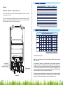
1
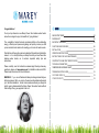
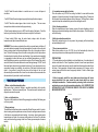
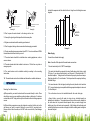
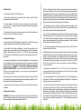
Congratulations!
You've just purchased a new Marey Power Gas tankless water heater
and will soon begin to enjoy the benefits of “going tankless.”
The availability of instant hot water, combined with the unit's outstanding
energy efficiency and space saving design, will quickly convince you that
you've made the best decision for meeting your home's hot water needs.
Take the time to thoroughly read and understand this safety and installation
manual in its entirety before you attempt to install your new Power Gas
tankless water heater, as it contains important safety tips and
instructions.
Please carefully read all instructions and warnings. Should you have any
questions, please visit www.marey.com for installation videos and FAQ.
Please keep this manual for future reference.
WARNING: If you are not familiar with basic plumbing and electricity, we
highly recommend that you employ the services of a professional to assist
you with this installation. Under no circumstances should you attempt to
install, repair, ordisassemble the Marey Power Gas water heater without
firsts hutting off any gas supplied to the unit.
02
QUICK START GUIDE
04
PACKING LIST
05
IMPORTANT WARNINGS
05
FUNCTIONS AND FEATURES
06
INSTALLATION
08
OPERATING INSTRUCTIONS
13
INSTRUCTIONS FOR DAILY MAINTENANCE
14
CONSTRUCTION AND PART IDENTIFICATION
15
TECHNICAL PARAMETERS
17
TEMPERATURE INCREASE CHART
17
TROUBLESHOOTING GUIDE
18
CUSTOMER SERVICE
19
OTHER PRODUCTS
19
03
POWER GAS MODELS
**WARNING: working with gas can be dangerous. If you are not familiar with local
building codes and basic gas plumbing practices please employ a professional to
install your water heater**
1. Water heater-Qty 1
2. Operating Instructions-Qty 1
3. Mounting Screws-4 Sets
1- Securely mount your water heater to the wall in an appropriate location using the
supplied hardware.
- You MUST install this water heater according to all directions and specifications
contained in this manual. Failure to properly install the heater can result in property
damage or severe injury or death by burning, explosion, or asphyxiation due to
carbon monoxide.
2- Install the venting (4” for 5L or 10L units, 5” for 16L units) per local building codes
and the instructions supplied.
- You MUST check the exhaust flue for obstructions at the initial installation and at
least annually thereafter.
3- Connect the gas lines (all connections are ½”). Use yellow Teflon tape at
threaded connections. Check carefully for gas leaks using soapy water and
correct as necessary before proceeding further.
- You MUST check all connections for gas leaks with soapy water before firing the
unit. This must be done at the initial install and after every propane bottle change if
using an LP model. If you detect a gas leak of any kind, DO NOT fire up your unit.
4- Connect the water lines (all connections are ½”). Use ½” or ¾” pipe or tubing for
the water supply and return. If water pressure or flow rates are questionable use
¾” lines to ensure maximum flow. You MUST use copper, CPVC or appliance
tubing intended for use in hot water applications for all hot water lines.
- You MUST check for gas leaks by smell. Understand that LP is heavier than air
and may sink to ground level. If you detect a gas leak of any kind, DO NOT fire up
your unit.
5- Check for and correct water leaks as necessary.
- You MUST observe the unit in operation for several cycles before leaving it
unattended.
6- Install the batteries in the battery compartment. Be sure the polarity of the
batteries is correct.
- Unit MUST be hung vertically, with the water and gas connections at the bottom
and the exhaust at the top.
7- Turn on the faucet and adjust the water and gas settings on the water heater as
needed for your specific environment and comfort. **USE CAUTION NOT TO GET
SCALDED WHILE ADJUSTING YOUR SETTINGS** Remember that more water
flow will usually result in less heating, and vice versa. Higher gas settings result in
more heating, and vice versa.
- You MUST use a carbon monoxide detector in conjunction with this, or any, gas
burning appliance.
8- Begin enjoying instant, energy efficient hot water for years to come!
Disclaimer: This document is intended as a quick reference only and does not
contain all of the important safety warnings and other information necessary to
safely operate your heater. For a complete list of safety warnings and instructions
please reference the instruction manual before operating your water heater.
- Do NOT expose the water heater to strong wind (including that from fans) or rain.
- Do NOT install the water heater near flammable or volatile substances. Do not
handle or store these substances near the heater (gasoline, acetone, motor oil,
paint thinners or any other flammable or volatile substance).
- Do NOT use tubing or piping that is aging or cracked in any way.
- Do NOT use this appliance with any type of gas other than that indicated on the
data plate located on the side of the unit. Death or severe injury may result.
- Do NOT attempt to modify the internal components of this appliance.
04
05
- Do NOT install the water heater in a sealed room or in a room with poor air
circulation.
- You MUST install the exhaust pipe to properly discharge the exhaust gases.
- Do NOT block the exhaust pipe or the air inlet at any time. This can cause
incomplete combustion and can lead to gas poisoning.
- When the water heater is in use, do NOT touch the body of the heater. Touch the
knobs only, as the body of the heater can become very hot to the the touch.
- Prevent scalds! While using the water heater, always check the water
temperature and adjust as needed before use.
WARNING! There is water contained in the coils of your water heater at all times. If
your water heater is exposed to freezing temperatures, the water in the coils could
freeze, causing a break in the heat exchanger of the unit, or the supply and return
lines. This kind of damage will result in water running freely into the space where
the water heater is located, with can cause flooding. If your water heater is installed
in a geographic location that sees very low sustained temperatures, you MUST
install a backflow preventer on your heater's vent pipe. This will ensure that cold air
cannot fall down into the water heater and cause freezing damage. DO NOT install
this water heater where it may be subjected to a freeze. If your water heater is in an
area where freezing is a possibility, you must turn off the water to the heater and
drain it of any water by using the valve stem at the bottom of the unit and
disconnecting the warm water line. Leave the valve stem and the warm water line
disconnected until you intend to use the water heater.
1. Water - controlled automatic ignition:
When water flow is detected, heating is provided immediately with a doubleignition device. The flame is sensed by ions. This sensitive control makes the unit
easy and convenient to operate.
4. Low water pressure start up function:
This unit requires only 8 PSI to fire, making it suitable for users with low water
pressure, or those who are using it to supply hot water to upper floors. Please note
that the water flow and water pressure are not the same. Sufficient flow is always
required to keep the overheat safety sensor from shutting the unit off.
5. Anti - freezing protection:
When the temperature is below freezing, remove the water discharge valve to
discharge accumulated standing water inside the internal pipes. This will keep the
unit from freezing.
6. Anti-dry combustion protection:
Should dry combustion occur for any reason, the gas supply will be immediately
and automatically shut off.
7. Over-pressure protection:
When water pressure is over 145 PSI, the unit will automatically relieve the
excessive pressure to avoid damage to its internal components.
PRECAUTIONS:
1. The water heater must be installed in a well-ventilated area. An exhaust pipe of
double walled steel for Class 3 appliances (located at most home improvement
stores in the water heater section) must be installed to discharge the exhaust from
the flame. During operation, the water heater consumes a lot of oxygen, so the
exhaust pipe and outlet hole must be properly installed. Refer to exhaust pipe
section for details.
- Failure to properly install the room intake and exhaust pipe will cause
oxygen depletion in the area around the water heater, which can cause
incomplete combustion. Carbon monoxide poisoning, death and serious
accidents can occur due to incomplete combustion. ALL USERS OF GAS
APPLIANCES OF ANY TYPE SHOULD EMPLOY THE USE OF A CARBON
MONOXIDE DETECTOR.
Exhaust fan
2. Auto - cut off protection:
The auto-cut-off protection will shut off the gas supply immediately if the flame goes
out for any reason.
3. Energy savings:
The advanced combustion system comes with a Winter/Summer switch. In winter,
when incoming water temperatures are lower, the winter setting increases the size
of the flame to compensate with extra heating. In summer, when incoming water
temperatures are higher, the summer setting reduces the flame.This provides
more comfort and energy savings in the form of lower gas consumption in warmer
months.
06
There shall be a air inlet
and a exhaust outlet.
Air inlet
Drawing 01
07
c) Install the expansion bolt into the drilled hole. Hang the unit utilizing the screws
supplied.
Washer
The water heater must not be
installed outside.
Drawing 03
25"
Drawing 02
Nut
29"
The water heater must not be
exposed to strong wind.
Expansion Screw
2. Don´t expose the water heater to the strong wind or rain.
18"
Heater Case
3. Use only the type of gas that is specified on the name plate.
4. All gas connections should be made by a professional.
5"
7,5"
5. Don't use pipes, tubing or other connections that are aging or cracked.
6. Do not use with water pressures lower than 8 PSI. Do not use with lower GPM's
than indicated on the flow chart for your unit.
7. The water heater shouldn't be installed above cooking appliances, such as
ovens or stoves.
8"
Drawing 04
Water Supply
Connect the cold water inlet supply
Note: Use white Teflon tape at all threaded water connections
8. The water heater should be installed a minimum of 15 feet from any stairs or
emergency exits.
9. The water heater must be installed vertically, according to the mounting
instructions.
10. The water heater must not be installed near flammable or volatile substances.
Mounting Your Water Heater
a)When possible, your water heater should be mounted directly to studs. There
should be a screw in every available mounting location on the heater. If studs are
not available, do NOT hang unit directly from sheetrock without utilizing expansion
screws.
b) When utilizing expansion screws for sheetrock mounting, hold the unit on the
wall where you want it mounted. Mark with a pencil the (4) mounting holes.
Remove the unit from the wall, and drill 3/8” holes on each mark. (See drawings
below).
08
- The cold water inlet joint is ½” NPT threaded pipe.
- The water inlet should be connected by using flexible heavy duty tubing or rigid
PVC pipe. If you choose flexible tubing, you will need a ½” threaded male to ½”
hose barb adapter. Tubing should be secured with properly sized hose clamps.
Rigid pipe should be ½” male threads. Teflon tape should be employed with any
threaded fittings.
- The inner diameter of the inlet pipe (including the valve) should not be less than
3/8”. Larger diameter pipe is acceptable with the appropriate adapters to reduce to
½” at the inlet joint.
- The cold water valve must be installed inline with the water inlet pipe.
- Always flush a new unit with water to clear out any collected deposits or
debrisprior to installation. The supplied screen filter must be correctly installed in
the cold water inlet to prevent mineral deposits from your water supply from
building up in the unit's water valve assembly. After flushing with cold water and
confirming that there is no residue in the pipe, install the rubber gasket and tighten
the water inlet joint.
09
Hot Water Outlet
- The hot water outlet joint is 1/2”NPT pipe thread.
- The hot water outlet should be connected by flexible tubing or rigid PVC of the
type intended for use with hot water.
- The inner diameter of the water outlet pipe (including the valve) shouldn´t
be less than 3/8”. Larger diameter pipe is acceptable as long as the appropriate
adapters are used.
- After connecting, fully open the cold water supply to confirm the flow of water and
to check for leaks. Correct leaks as necessary.
Installing the Gas Supply
The gas inlet joint is 1/2”NPT pipe thread. Very Important: Use Teflon tape for gas
or gas pipe paste between the unit and the gas inlet pipe connector.
-For small bottle Liquid Propane installations: Connect the gas supply to your
propane bottle using a standard rubber Liquid Propane hose and low pressure
regulator. Optimal pressure for your unit is .41-.5 PSI, the same as a typical gas
grill. Pressures set outside this range may result in inconsistent behavior from your
water heater.
This kind of damage will result in water running freely into the space where the
water heater is located, with can cause flooding. If your water heater is installed in a
geographic location that sees very low sustained temperatures, you MUST install a
backflow preventer on your heater's vent pipe. This will ensure that cold air cannot
fall down into the water heater and cause freezing damage. Damage to the unit or
residence caused by freezing is not covered under warranty and responsibility for
this type of damage is disclaimed by Marey Heater Corporation.
- All venting must be done in accordance with local codes and regulations. Local
building codes from city to city and state to state will vary. Some jurisdictions may
allow venting material not allowed by other jurisdictions.
- ALL jurisdictions in North America allow for Z-Vent material to be used for venting
tankless hot water heaters. The condensation of a tankless water heater is slightly
more acidic than that of a standard water heater. Z-Vent is double walled stainless
steel vent pipe made specifically for venting tankless heaters. Z-Vent is intended
for lifetime use and will never corrode or rust.
- Z-Vent material is available at most home improvement stores, and can be found
at many online retailers as well.
- SOME jurisdictions in North America allow for B-Vent to be used. B-Vent is double
walled galvanized vent pipe made for standard water heaters and stove vent pipe.
B-Vent is not lifetime material and will eventually corrode after extended use.
Before deciding what material to use, you MUST check your local building codes to
see what is allowed in your jurisdiction. If you choose to use B-Vent, you MUST
check it at least monthly for corrosion and replace vent pipes immediately if
corrosion is detected.
- For whole house Liquid Propane or Natural Gas Installations: The unit should be
connected directly to the home gas supply using black iron gas pipe or the braided
metal gas appliance hoses located in the water heater section of your local home
improvement store. WARNING: THIS TYPE OF CONNECTION MUST BE
MADE BY A PROFESSIONAL. Please note that Natural Gas units require .25-.5
PSI for your unit to operate correctly. If you are unsure of your gas pressure,
contact your gas company.
- Diameter of the vent pipe is 4” for 5L, 4” for 10L, and 5” for 16L units. Use the
coupler provided with your unit for installation on the 5L and 10L units. Vent pipe
attaches directly to the unit in 16L models.
After the gas inlet is connected, open the gas supply valve and check for gas leaks
at all connections by spraying with soapy water and watching for bubbles. Do not
skip this step! Adjust or repair leaks as needed.
- Through wall installations: Use (2) 45 degree elbows, (1) piece of straight pipe no
longer than 18” in length, one piece of straight pipe no longer than 42” in length, one
wind/rain cap and one condensation drain.
- All gas connections must be made in accordance with local building codes and
regulations.
- From the outlet at the top of the water heater, attach the first 45 degree elbow with
a vent pipe coupler to secure it to the unit. Once the elbow is attached, use it as a
guide to cut a hole through the wall at a 45 degree upward angle, at a slightly larger
diameter than the outlet pipe. Install the 18” piece of straight pipe to the 45 degree
elbow and pass it through the hole in the wall. Note: If the overall thickness of your
wall exceeds 18”, the length of the first pipe can be extended up to 24”. If this is the
case, reduce the length of the second pipe to 36”. Total venting distance should not
exceed 60”.
Installing the Exhaust Pipe
WARNING! There is water contained in the coils of your water heater at all times. If
your water heater is exposed to freezing temperatures, the water in the coils could
freeze, causing a break in the heat exchanger of the unit.
10
11
- Attach the second 45 degree elbow on the other side of the wall, turning the angle
upward to run parallel with the wall. Install the second piece of flute pipe into the
elbow, parallel to the outside wall. Utilize galvanized steel brackets or clamps as
necessary to secure the piping. Install the rain/wind cap on top of the second piece
of exhaust pipe..
- Install a condensation drain on the portion of pipe located outside the structure.
- Through the roof installations: Use one piece of straight pipe, 60” or shorter, a
wind/rain cap and a condensation drain. Attach directly to the outlet of the unit (16L
units), or using the coupler supplied (5L and 10L units).
- Drill a hole through the roof and ceiling slightly larger than the vent pipe diameter.
Attach pipe to the top of the unit and go straight up and out the roof. Install
rain/wind cap on top of vent pipe. Total vertical distance must not exceed 60”. Roof
clearance must be at least 12”.
- Fresh air intake: The room in which the heater is located must have an air inlet not
less than .75 square feet (roughly 9” x 12” or larger).
Wind/rain cap
Straight pipe 42" or less
Straight pipe 18" or less
Coupler (island 10L only)
45º elbow
Outlet
- After installation is complete, open the battery compartment located at the bottom
of the unit and install two D Cell batteries. Check the door of the battery
compartment for correct battery position.
- Open the hot water on a nearby faucet. Confirm proper water flow through the
unit and out of the faucet. (You should hear a “clicking” sound from the unit-this is
the ignitor activating). Turn the water back off.
- Start the gas supply. Check again for gas leaks using soapy water and correct as
necessary.
- Open the hot water faucet. You should hear the ignition clicking, and hot water
should begin flowing. Sometimes, if there is air in either the water or gas supply
lines, you will not get immediate combustion. If this is the case, turn the water on
and off several times to clear the water and gas lines of any air pockets that may be
present.
- All water heaters have a seasonal summer/winter switch to meet your water
temperature needs. This is because extra heating may be required when incoming
water temperatures are lower (winter), and less heating is required when incoming
water temperatures are higher (summer). Use the summer setting when incoming
water temperatures are a little higher. Use the winter setting when incoming water
temperatures are a little lower.
- When the water supply is turned off, the water heater will stop working. When you
turn the water back on, the water heater will reignite. Please note that if you use the
hot water multiple times in quick succession, the water may be excessively hot for
one or two seconds. Please wait for the temperature to adjust before using.
- If you close the water inlet valve or the water outlet valve, the water heater will shut
off immediately. Shut off the gas supply after use.
Water heater
Wall
Cap
Through Roof
Straight pipe
12" min
Specification
Roof
60" max
Ceiling
Coupler (5L and 10L units)
Sighting Window
Winter/Summer knob
Instruction
Gas controlling knob
Water controlling knob
Outlet
Water heater
Drawing 05
(D). Water heater type D
(Drawing 1)
**Note: If your situation requires a vent pipe distance of longer than 60”, a low CFM duct
booster fan may need to be employed to ensure proper venting of the unit.
12
13
Sighting Window
Specification
Do NOT use strong detergents, benzene, gasoline, or other flammable agents to
clean the unit.
Winter/Summer knob
Instruction
Regularly remove and wash the stainless steel filter in the cold water inlet.
Gas controlling knob
Water controlling knob
During operation, take note of the flame and discontinue use if abnormal
combustion is detected.
Avoid accidents. DO NOT modify this unit in any way.
Drawing 06
1. If a gas leak is detected at any time, close the main gas valve immediately. The
Marey service center or your local gas company should be contacted for repair.
5L and 10L units
2. Before going to sleep or leaving the house, the gas supply should be shut off.
3. Do not block the exhaust pipe or the air inlet. This can cause incomplete
combustion and lead to gas poisoning.
4. During operation, check the fire through the sight glass for normal combustion.
Check for a compact, blue flame. Tall or excessively orange flames indicate
abnormal combustion. If there is abnormal combustion, close the gas valve
immediately and contact the Marey service center or your gas company for
maintenance.
5. When outdoor temperatures are below 32 degrees F and pipe freezing may
occur, any water remaining in the unit after use should be discharged to avoid
freezing. Water should be discharged in the following manner:
Back plate
Gas -collecting
roof
Heat exchanger
Temperature
controller
Burner
Ignition pin I
Ignition pin II
a) Turn off the gas supply valve, turn off the tap water supply valve, and turn the
water temperature adjusting switch to the low temperature position. Turn on the
hot water supply valve and remove the water discharge valve to discharge the
water remaining in the unit. Reinstall the water discharge valve.
Thermocou
Gas adjusting
valve
Water adjusting
valve
Solenoid valve
Check the gas pipes, hoses, and vent pipes regularly. If you find joints that are not
tightly secured or if there are cracks or corrosion anywhere, you should stop using
the heater and perform the necessary maintenance immediately.
Microactive switch
Ignition module
Hot water
outlet pipe
Battery box
Water discharge
valve
Gas inlet pipe
Check regularly for water or gas leaks and correct immediately.
Regularly clean the surface of the water heater to remove dirt or dust with a wet
cloth, and then use a dry cloth to remove moisture. For hard to remove dirt, please
use a mild spray cleaner or detergent.
14
Water inlet pipe
Drawing 07
15
16L units
IMPORTANT WARNING - PLEASE TAKE NOTE
If your unit is a 16L model, you MUST follow this diagram for correctly connecting
water and gas to the unit.
The water and gas connection diagram contained on the previous page accurate
only for the 5L and10L Power Gas models. If you have a 5L or 10L unit, please
follow the diagram contained on the previous page.
TECHNICAL SPECIFICATIONS GAS 5L
GAS 10L
GAS 16L
Hot Water Outlet per Minute
5 LPM / 1.3 GPM
10 LPM / 2.7 GPM
16 LPM / 4.2 GPM
Heat Loss
34,614 BTU/h
79,228 BTU/h
111,903 BTU/h
Activation Flow Rate
10 PSI
10 PSI
10 PSI
Maximmum Flow Rate
2 GPM
3.1 GPM
4.3 GPM
Width x Height x Depth
11,4" x 17" x 4,7" 13,6" x 23,6" x 6,9" 6,5" x 27,9" x 18,2"
Weight
11 lbs
29 lbs
21 lbs
Gas Type
Liquid Propane Gas or Natural Gas
Related Gas Pressure (PSI)
0.25 up to 0.5 PSI (NG) & 0.4 (LPG)
Exhaust Discharge Mode
Flue Duct Type
Aplicable Water Pressure
3.6 - 145.0 PSI / 0.25 - 10 bar
Ignition
2D Cell Battery Powered (not included)
Energy Efficiency
54% - 87%
* No need for electricity, starts with pulse ignition, powered by 2 D cell batteries.
TEMPERATURE INCREASE PER GPM
Model
GA5L
Gas
0.5 1.0 1.5 2.0 2.5 2.7 3.0 3.5 4.0 4.3
Setting GPM GPM GPM GPM GPM GPM GPM GPM GPM GPM
Highest 129º 64º
43º
32º
-
-
-
-
-
-
Lowest 34º
11º
9º
-
-
-
-
-
-
100º 67º
50º
40º
37º
30º
-
-
-
34º
23º
17º
14º
13º
9º
-
-
-
143º 95º
71º
57º
52º
48º
41º
36º
33º
44º
22º
18º
16º
15º
13º
11º
10º
Highest
-
17º
GA10L
Lowest 68º
GA16L
Highest
-
Lowest 88º
29º
*Highest gas setting: set for Winter/High
*Lowest gas setting: set for Summer/Low
*With and without LCD panels.
Note: If your gas model features an LCD panel, the digital display will indicate the outgoing
water temperature.
Gas inlet pipe
Hot water outlet pipe
Water inlet pipe
Drawing 08
16
This information is intended as a guideline based on typical residential environments.
Temperature increases will vary depending on the environment in which the heater is used.
Variables such as very low incoming water temperature or higher than average gas pressure
can result in higher temperature increases. Higher incoming water temperature or lower
than average gas pressure can result in lower temperature increases. ALWAYS test the
water with your hand to confirm suitable temperature before use.
Temperature increases listed are based on use of the water heater under optimal conditions
with an incoming water temperature of 48ºF. Variable factors such as incorrect or imperfect
installation or warmer incoming water temperature may yield different results.
17
At Marey, we pride ourselves on the excellence of our customer
service and support team.
Please feel free to contact us if you have any questions about our
products, warranty service, or if you need assistance installing a
unit. We also strive for continuous improvement, so we welcome
your comments, feedback and suggestions.
1-855-MAREY-55
[email protected]
Marey proudly manufactures water heaters and accessories for use in almost any
application. Please visit our website to learn more about other Marey products.
Not enough water flow
through the unit
Increase water flow through
the unit
Delbrey Street, 211
San Juan, Puerto Rico
00912
Tel: 1-512-332-2229
Toll Free: 1-855-627-3955
1-855-MAREY-55
www.marey.com
18
19