1
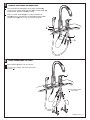
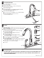
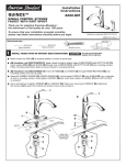
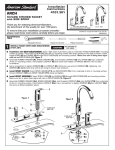
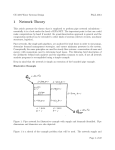
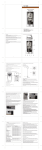
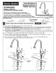
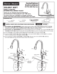
Installation
Instructions
4101.301 Serie
ARCH
HI-FLOW KITCHEN FAUCET
with SIDE SPRAY
Thank you for selecting American-Standard...
the benchmark of fine quality for over 100 years.
4101.301 shown with
optional escutcheon 4101.000P
To ensure that your installation proceeds smoothly-please read these instructions carefully before you begin.
4101.301
Certified to comply with ANSI A112.18.1M
M968583 Rev.1.2
RECOMMENDED
TOOLS
Adjustable Wrench
1
Regular Screwdriver
INSTALL FAUCET WITH DECK ESCUTCHEON
(4101.351)
CAUTION
Phillips Screwdriver
Channel Locks
Turn off water at
main supply.
Installation with DECK ESCUTCHEON: Apply a light bead of plumbers putty to underside of ESCUTCHEON (1) if mounting
surface is uneven. Place ESCUTCHEON (1) onto sink or mounting surface with large opening to the right as shown. Insert
supply HOSES (2) and SHANK (3) through ESCUTCHEON (1) and mounting surface. Make sure slot in fitting base aligns
with tab on ESCUTCHEON (1). Figure 1.
Assemble RUBBER WASHER (4), BRASS WASHER (5), and threaded LOCKNUT (6) onto SHANK (3) from underside
of sink or mounting surface. Hand tighten LOCKNUT (6) and check that rotation of HANDLE (7) from HOT to COLD
is centered.
Use a screwdriver to tighten SCREWS (8) on LOCKNUT (6). Work your way around LOCKNUT (6), tightening the
SCREWS (8) slightly each time until all are snug to ensure even pressure.
Install SPRAY HOLDER: Insert SPRAY HOLDER (11) into ESCUTCHEON (1). From underside of sink or mounting surface
thread LOCKNUT (12) onto SPRAY HOLDER (11) shank and tighten.
Install SPOUT ASSEMBLY: Insert SPRAY HOSE (9) and SHANK (10) through ESCUTCHEON (1) and mounting surface.
Make sure slot in spout base aligns with tab on ESCUTCHEON (1). Figure 2.
Assemble RUBBER WASHER (4a), BRASS WASHER (5a), and threaded LOCKNUT (6a) onto SHANK (10) from underside
of sink or mounting surface. Hand tighten LOCKNUT (6a). Use a screwdriver to tighten SCREWS (8a) on LOCKNUT (6a)
the same as fitting installation above.
7
Figure 1
Figure 2
SLOT
3
11
1
2
ALIGN SLOT
AND TAB
TAB
SLOT
ALIGN SLOT
AND TAB
10
TAB
4
12
5
6
8
1
4a
8a
5a
6a
9
1a
INSTALL FAUCET WITHOUT ESCUTCHEON PLATE
(4101.115 with soap dish) (4101.350 less soap dish)
Insert SEAL WASHER (1) into ESCUTCHEON (2). Place ESCUTCHEON (2) onto sink or mounting surface. Insert supply
TUBES (3) and SHANK (4) through ESCUTCHEON (2) and mounting surface.Make sure slot in fitting base aligns with
tab on ESCUTCHEON (2). Figure 1.
Assemble RUBBER WASHER (5), BRASS WASHER (6) and threaded LOCKNUT (7) onto SHANK (4) from underside
of sink or mounting surface. Hand tighten LOCKNUT (7) and check that rotation of HANDLE (8) from HOT to COLD
is centered.
Use a screwdriver to tighten SCREWS (9) on LOCKNUT (7). Work your way around LOCKNUT (7), tightening the
SCREWS (9) slightly each time until all are snug to ensure even pressure.
Install SPRAY HOLDER: Insert SPRAY HOLDER (11) into ESCUTCHEON (12). Insert SEAL (14) into underside of
ESCUTCHEON (12). From underside of sink or mounting surface thread LOCKNUT (13) onto SPRAY HOLDER (11)
shank and tighten.
Install SPOUT ASSEMBLY: Insert SEAL WASHER (1a) into ESCUTCHEON (2a). Insert SPOUT HOSE (10) and SHANK (11)
through ESCUTCHEON (2a) and mounting surface. Make sure slot in spout base aligns with tab on ESCUTCHEON (2a).
Figure 2.
Assemble RUBBER WASHER (5a), BRASS WASHER (6a), and threaded LOCKNUT (7a) onto SHANK (11) from underside
of sink or mounting surface. Hand tighten LOCKNUT (7a). Use a screwdriver to tighten SCREWS (9a) on LOCKNUT (7a)
the same as fitting installation above.
8
Figure 2
Figure 1
SLOT
4
3
2
1
11
ALIGN SLOT
AND TAB
TAB
ALIGN SLOT
AND TAB
SLOT
11
12
14
2a
TAB
1a
5
13
6
7
9
5a
6a
7a
9a
2
MAKE WATER SUPPLY CONNECTIONS
10
RED STRIPE
2
Push HOSE END (1) with compression fitting onto COPPER TUBE (2) Make sure
HOSE and COPPER TUBE are fully engaged (approx.1/2" engagement). Use adjustable
wrench to tighten connections. Do not over tighten.
Turn off hot and cold water supplies before beginning.
Connect FLEXIBLE SUPPLIES (3) directly to wall supplies. Connection on fitting
supplies are 3/8" compression. Connect left supply (Marked with a Red Stripe)
to Hot and right supply to Cold wall supply. Use adjustable wrench to tighten
connections. Do not over tighten.
Faucet supplies are 24-1/2" long from faucet base.
Note: If additional supply length is required, installer must purchase
those parts separately.
Important: If SUPPLY HOSES (3) are too long, loop as illustrated to avoid kinking.
3
1/2"
ENGAGEMENT
1
COLD
HOT
M968583 Rev.1.2
3
CONNECT SPRAY HOSE AND SPOUT HOSE
Feed HAND SPRAY HOSE (1) through SPRAY HOLDER (2).
Use wrench to tighten COUPLING NUT (3) on SPRAY HOSE (1)
to SIDE SPRAY CONNECTION (4) on fitting.
Make sure SEAL WASHER (5) is installed in COUPLING
NUT (6). Connect threaded end of HOSE (7) to SPOUT HOSE
COUPLING NUT (6) from fitting. Use wrench to tighten.
1
2
6
5
4
7
4
3
CHECK CONNECTIONS FOR LEAKS.
Move HANDLE (1) down into "off" position.
Turn on water supplies and check connections
for leaks.
1
CHECK CONNECTIONS
FOR LEAKS
M968583 Rev.1.2
5
TEST INSTALLED FAUCET
Move HANDLE (1) down into "off" position.
Remove AERATOR (2).
Operate handle up and down, in COLD and HOT positions,
to flush water lines thoroughly.
Replace AERATOR (2).
1
With HANDLE (1) down in "off" position, pull HAND SPRAY (3)
from holder and direct SPRAY END (3) into sink.
2
Check HAND SPRAY (3) operation:
With faucet on push BUTTON (4) to activate HAND SPRAY (3).
Release BUTTON (4) to stop spray and return
HAND SPRAY (3) to holder.
4
3
6
SERVICE
3
2
If faucet drips, operate HANDLE several times from "off" to "on." Do not
apply excessive force.
1
Clogged CARTRIDGE outlets or inlets may cause reduced flow.
To clean, first turn off water supply then:
4
Remove INDEX BUTTON (1), loosen HANDLE SCREW (2)
and remove HANDLE (3).
Unthread ESCUTCHEON CAP (4). Unthread three
MOUNTING SCREWS (5).
Lift CARTRIDGE (6) off MANIFOLD (7) and remove
CARTRIDGE SEALS (8).
5
Clean MANIFOLD (7), CARTRIDGE (6) ports and SEALS (8).
Place SEALS (8) into CARTRIDGE PORTS (6a).
Place CARTRIDGE (6) onto MANIFOLD (7) and tighten MOUNTING
SCREWS (5) alternately.
Replace ESCUTCHEON CAP (4), HANDLE (3), tighten HANDLE
SCREW (1) and install INDEX BUTTON (2).
6
6a
8
7
Test fitting.
7
CARE INSTRUCTIONS:
DO: SIMPLY RINSE THE PRODUCT CLEAN WITH CLEAR WATER. DRY WITH A SOFT COTTON FLANNEL CLOTH.
DO NOT: DO NOT CLEAN THE PRODUCT WITH SOAPS, ACID, POLISH, ABRASIVES, HARSH CLEANERS, OR A
CLOTH WITH A COARSE SURFACE.
M968583 Rev.1.2