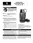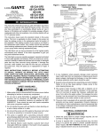
1
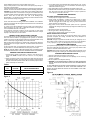
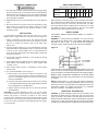
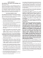
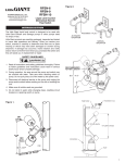
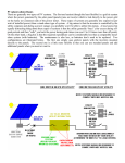
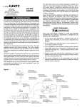
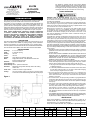
Franklin Electric Co., Inc.
P. O. Box 12010
Oklahoma City, OK 73157-2010
405.947.2511 • Fax: 405.947.8720
www.LittleGiantPump.com
[email protected]
are capable of operating with the motor housing partially
exposed for extended periods of time, providing sufficient motor
cooling and bearing lubrication, however, for the best cooing
and longest motor life, the liquid level being pumped should
normally be above the top of the cast iron motor housing.
9S-CIM
9S-CIA-RFS
Submersible
Sewage Ejector Pump
SAFETY GUIDELINES
WARNING: RISK OF ELECTRIC SHOCK. This pump is supplied with a
grounding conductor and/or grounding-type attachment plug. To reduce the
risk of electric shock, be certain that it is connected to a properly grounded
grounding-type receptacle.
Your 115V sewage ejector pump is equipped with a 3-prong electrical plug.
The third prong is to ground the pump to prevent possible electrical shock
hazard. Do not remove the third prong from the plug. A separate branch circuit
is recommended. Do not use an extension cord.
When a pump is in a basin, etc., do not touch motor, pipes or water until unit
is unplugged or shut off. If your installation has water or moisture present,
do not touch wet area until all power has been turned off. If shut-off box is not
accessible, call the electric company to shut off service to the house, or call
your local fire department for instructions. Failure to follow this warning can
result in fatal electrical shock.
The flexible PVC jacketed cord assembly mounted to the pump must not be
modified in any way, with the exception of shortening the cord to fit into a
control panel. Any splice between the pump and the control panel must be
made within a junction box and mounted outside of the basin, and comply with
the National Electrical Code. Do not use the power cord for lifting the pump.
The pump motor is equipped with an automatic resetting thermal protector and
may restart unexpectedly. Protector tripping is an indication of motor overloading
as a result of operating the pump at low heads (low discharge restriction), excessively
high or low voltage, inadequate wiring, incorrect motor connections, or a defective
motor or pump.
1. Read all instructions and safety guidelines thoroughly. Failure to follow the
guidelines and the instructions could result in serious bodily injury and/or
property damage.
2. DO NOT USE TO PUMP FLAMMABLE OR EXPLOSIVE FLUIDS SUCH AS
GASOLINE, FUEL OIL, KEROSENE, ETC. DO NOT USE IN EXPLOSIVE
ATMOSPHERES OR HAZARDOUS LOCATIONS AS CLASSIFIED BY NEC,
ANSI/NFPA70. FAILURE TO FOLLOW THIS WARNING CAN RESULT IN
PERSONAL INJURY AND/OR PROPERTY DAMAGE.
3. During normal operation the pump is immersed in water. Also, during rain
storms, water may be present in the surrounding area of the pump. Caution
must be used to prevent bodily injury when working near the pump:
a. The plug must be removed from the receptacle prior to touching, servicing
or repairing the pump.
INTRODUCTION
This instruction sheet provides you with the information required to safely own
and operate your product. Retain these instructions for future reference.
The product you have purchased is of the highest quality workmanship and
material, and has been engineered to give you long and reliable service. This
product has been carefully tested, inspected, and packaged to ensure safe
delivery and operation. Please examine your item(s) carefully to ensure that no
damage occurred during shipment. If damage has occurred, please contact the
place of purchase. They will assist you in replacement or repair, if required.
READ THESE INSTRUCTIONS CAREFULLY BEFORE ATTEMPTING
TO INSTALL, OPERATE, OR SERVICE YOUR PRODUCT. KNOW THE
PRODUCT’S APPLICATION, LIMITATIONS, AND POTENTIAL HAZARDS.
PROTECT YOURSELF AND OTHERS BY OBSERVING ALL SAFETY
INFORMATION. FAILURE TO COMPLY WITH THESE INSTRUCTIONS
COULD RESULT IN PERSONAL INJURY AND/OR PROPERTY DAMAGE!
DESCRIPTION
Little Giant Submersible Sewage Ejector Pumps are recommended for use in
basins or lift stations and suitable for pumping sewage, effluent, wastewater
and other non-explosive, non-corrosive liquids with up to 2” spherical solids.
Automatic operation can be achieved with the use of the RFS Remote Float Switch.
Other accessories such as basins, check valves and covers are also available.
Discharge:
Intake:
Housing:
Volute:
Impeller:
Motor:
SPECIFICATIONS
2” or 3” NPT vertical
2” diameter opening
Cast iron
Cast iron
Vortex design with pressure relief vanes
Single-phase induction 1750 RPM with automatic reset
thermal overload protection
Hardware:
300 series stainless steel
Thrust Bearing: Ball
Radial Bearing: Sleeve – permanent lubrication
Shaft Seal:
Mechanical, spring loaded, stationary carbon with rotating
ceramic seat
Power Cord:
16 AWG 3-conductor copper stranded
Cooling:
The motor housing contains a cooling oil to provide cooling
for the motor and to lubricate bearings and seals. These pumps
b. To minimize possible fatal electrical shock hazard, extreme care should
be used when changing fuses. Do not stand in water while changing
fuses or insert your finger into the fuse socket.
4. Do not run the pump in a dry basin. If the pump is run in a dry basin, the
surface temperature of the pump will rise to a high level. This high level
could cause skin burns if the pump is touched and will cause serious
damage to your pump.
5. Do not oil the motor. The pump housing is sealed. A high grade dielectric
oil devoid of water has been put into the motor housing at the factory. Use
of other oil could cause serious electric shock and/or permanent damage
to the pump.
6. This pump’s motor housing is filled with a dielectric lubricant at the factory
for optimum motor heat transfer and lifetime lubrication of the bearings.
Use of any other lubricant could cause damage and void the warranty.
This lubricant is non-toxic; however, if it escapes the motor housing, it
should be removed from the surface quickly by placing newspapers or
other absorbent material on the water surface to soak it up, so aquatic life
is undisturbed.
7. In any installation where property damage and/or personal injury might result from
an inoperative or leaking pump due to power outages, discharge line blockage, or
any other reason, a backup system(s) and/or alarm should be used.
Figure 1
INSTALLATION
Pump must be installed in a suitable gas-tight basin which is at least 18” in
diameter and 24” deep, and vented in accordance with local plumbing codes.
Pump features a 2” or 3” female NPT discharge.
Pump can be installed with ABS, PVC, polyethylene or galvanized steel pipe.
MODEL NO.
9S-CIM
LISTING
UL
VOLTS
115
HP
4/10
AMPS/ WATTS
13.0/1015
GPM @ HEAD
5’
10’
15’
80
50
16
SHUT OFF (ft.)
18.0
P.S.I.
7.8
PWR CRD (ft.) WT. (lbs.)
15
33
9S-CIM
—
230
4/10
6.5/1120
80
50
16
18.0
7.8
15
33
9S-CIA-RFS
UL
115
4/10
13.0/1015
80
50
16
18.0
7.8
15
34
1
Proper adapters are required to connect plastic pipe to pump.
Pump must be placed on a hard level surface. Never place pump directly on
clay, earth or gravel surfaces.
A check valve must be used in the discharge line to prevent back flow of liquid into
the basin. The check valve should be a free flow valve that will easily pass solids.
CAUTION: For best performance of check valves, when handling solids install in
a horizontal position or at no more than at a 45° angle. Do not install check valve
in a vertical position as solids may settle in valve and prevent opening on start-up.
When a check valve is used drill a 3/16” hole in the discharge pipe
approximately 1” to 2” above the pump discharge connection and below check
valve to prevent air locking of the pump.
WIRING
Check local electrical and building codes before installation. The installation
must be in accordance with their regulations as well as the most recent National
Electrical Code (NEC).
To conform to the National Electrical Code, all pumps must be wired with 14
AWG or larger wire. For runs to 250’, 14 AWG wire is sufficient. For longer runs
consult a qualified electrician or the factory.
Pump should be connected or wired to its own circuit with no other outlets
or equipment in the circuit line. Fuses and circuit breaker should be of ample
capacity in the electrical circuit. See Table 2.
REMOTE FLOAT SWITCH LEVEL CONTROL
The RFS series pumps are equipped with a remote float switch level control.
This level control is sealed in a polypropylene float cylinder. For automatic
operation, the pump must be plugged or wired into a remote float switch. Pump
will run continuously if plugged directly into an electrical outlet.
When the level rises in the basin, the cylinder floats up with the level. When the
cylinder position is at an angle of about 45°, the switch activates and starts the
pump motor.
As the level draws down, the cylinder floats down and when it is again at an
angle of about 45°, the switch deactivates, and the pump motor stops.
NOTE: BE CERTAIN PUMP IS SECURE IN BASIN AND CYLINDER FLOATS
UNOBSTRUCTED WITHOUT TOUCHING THE BASIN WALLS OR PLUMBING.
REMOTE FLOAT SWITCH INSTALLATION
1. The float switch consists of three parts: 1) switch, 2) cord clamp, and 3)
clamp screw. NOTE: If screw is lost, use a #10-16 x 1/2” long tapping
screw.
2. Attach cord clamp to pump cover as shown in the switch instruction manual
packaged with the switch. The clamp and pump handle must be positioned
as shown to allow free operation of float. Be sure to locate pump and switch
power cords away from switch float.
Table 1
H.P.
VOLTAGE
FUSE OR
CIRCUIT BREAKER AMPS
4/10
115
20
4/10
230
15
Figure 2
2
3. A 3.5” tether length is recommended. When a tether length of 3.5” is used,
a minimum basin diameter of 18” is recommended. The tether length is
measured as shown in Figure 3.
4. After desired tether length is established, hand-tighten clamp screw.
5. TESTING: Without water in basin plug pump power cord into switch in-lineplug. Plug switch into outlet. Lift float and watch for pump to operate. Do
not run pump for more than 5 seconds.
TESTING PUMP OPERATION
RFS SERIES SEWAGE EJECTOR PUMPS
1. These pumps are equipped with a remote float switch.
2. These pumps are installed in a basin with a sealed cover, so switch
operation cannot be observed. The sump cover usually will have a spare
hole that is plugged with a rubber plug. This plug can be removed and
switch operation can be observed.
3. Plug power cord and remote float switch power cord into a grounded
receptacle with voltage consistent with pump voltage as indicated on pump
nameplate.
4. Run water into basin until pump starts.
5. Be sure gate valve in discharge line is open.
6. Allow pump to operate through several on-off cycles.
MANUAL SEWAGE EJECTOR PUMPS
The pump cord for these pumps can be plugged directly into a properly
grounded receptacle with voltage consistent with pump nameplate for
continuous pump operation.
CAUTION: This type of operation should be used only for emergency use or
when a large volume of water is to be pumped. Pump must not be allowed to
run dry. If pump is run dry, it may damage pump and void the warranty.
MAINTENANCE AND SERVICE
If pump does not operate properly, consult the Troubleshooting Chart. If trouble
cannot be located with these steps shown, consult your pump dealer or take
pump to a Little Giant authorized service center.
CAUTION: When working on pump or switch, always unplug pump power cord in
addition to removing fuse or shutting off circuit breaker before working on pump.
CLEANING IMPELLER AND VOLUTE
1. Remove screws that hold volute to motor housing.
2. Remove volute and clean impeller and volute passage. Do not use strong
solvents on impeller.
3. Be sure impeller turns freely after cleaning.
4. WARNING: DO NOT REMOVE IMPELLER. REMOVAL OF IMPELLER REQUIRES
SPECIAL TOOLS AND IS TO BE DONE ONLY BY AN AUTHORIZED SERVICE
CENTER.
DO NOT REMOVE MOTOR HOUSING COVER. WARRANTY IS VOID IF MOTOR
HOUSING COVER, IMPELLER OR SEALS HAVE BEEN REMOVED. ANY
REPAIR ON MOTOR MUST BE DONE BY AN AUTHORIZED LITTLE GIANT
SERVICE CENTER.
Figure 3
ITEM
NO.
PART
NO.
9S-CIM
509400
9S-CIA-RFS
509450
9S-CIA-RFS
509500
9S-CIM
509520
9S-CIM, 3” DISCH.
14940723
9S-CIM, 3” DISCH.
14940724
Figure 4
PARTS DESCRIPTION
1
108101 Handle, Pump
1
1
1
1
1
1
2
950315 Remote Float Switch
--
--
1
--
--
--
2
950307 Remote Float Switch
--
--
--
1
--
--
3
902516 Screw, Tapping #10-24 x 1/2”
--
--
1
1
--
--
4
927027 Clamp, Cord
--
--
1
1
--
--
5
915907 Bolt, Hex Head
4
4
4
4
4
4
6
921103 Washer, Lock
4
4
4
4
4
4
7
111415 Volute, 2” Discharge
1
1
1
1
--
--
7
111540 Volute, 3” Discharge
--
--
--
--
1
1
8
950905 Ty-Rap (not shown)
--
--
1
1
1
1
TROUBLESHOOTING INFORMATION
PROBLEM
Pump does not turn on.
NOTE: Before troubleshooting
automatic control, check to see
that pump operates on manual
control. To do this, unplug from
in-line float switch plug. Plug
pump power cord into wall outlet.
If pump works, proceed to check
switch, if not, fault is in pump or
power supply.
PROBABLE CAUSES
Pump not plugged in.
Plug in pump.
Circuit breaker shutoff or fuse removed.
Turn on circuit breaker or replace fuse.
Accumulation of trash on mercury float switch.
Clean float.
Remote float switch obstruction.
Check float path and provide clearance.
Defective switch.
Disconnect switch, check with ohmmeter.
Open-infinitive resistance, closed-zero.
Defective motor.
Have pump serviced.
Remote float switch obstruction.
Check float path and provide clearance.
Pump is air locked.
Shut power off for approximately 1 minute, then restart. Repeat
several times to clear air from pump. If system includes a
check valve, a 3/16” hole should be drilled in discharge pipe
approximately 2” above discharge connections.
Liquid inflow matches pump capacity.
Larger pump required.
Defective switch.
Disconnect switch, check w/ohmmeter, Open-infinitive
resistance, closed-zero.
Pump will not shut off.
Pump runs but does not
discharge liquid.
Pump does not deliver rated
capacity.
Pump cycles continually.
CORRECTIVE ACTIONS
Loose connection in level control wiring.
Check control wiring.
Check valve installed backwards.
Check flow indicating arrow on check with ohmmeter. Openinfinitive resistance, closed-zero.
Check valve stuck or plugged.
Remove check valve and inspect for proper operation.
Lift too high for pump.
Check rating table.
Inlet to impeller plugged.
Pull pump and clean.
Pump is air locked.
(See corrective action above.)
Lift too high for pump.
Check rated pump performance.
Low voltage, speed too slow.
Check for proper supply voltage to make certain it
corresponds to nameplate voltage.
Impeller or discharge pipe is clogged.
Pull pump and clean. Check pipe for scale or corrosion.
Impeller wear due to abrasives.
Replace worn impeller.
No check valve in long discharge pipe allowing
liquid to drain back into basin.
Install a check valve in discharge line.
Check valve leaking.
Inspect check valve for correct operation.
Basin too small for inflow.
Install larger basin.
3
LIMITED WARRANTY
SUMP, EFFLUENT & RESIDENTIAL SEWAGE
Little Giant #8E, #9E, #10E, #14EH and #16EH Series Submersible Effluent
Pumps are recommended for use in sumps, basins or lift stations and suitable
for pumping basement drainage water, effluent, wastewater and other nonexplosive, non-corrosive, non-abrasive liquids not above 140°F with up to 3/4”
spherical solids handling ability. (NOT TO BE USED FOR SEWAGE WATER
EXCEPT TO PUMP SEPTIC TANK EFFLUENT.)
Little Giant #9S, #10S, #14S, and #16S Series Submersible Sewage Ejector
Pumps are recommended for use in sumps, basins or lift stations and suitable
for pumping sewage, effluent, wastewater, and other non-explosive, noncorrosive, non-abrasive liquids not above 140°F with up to 2” spherical solids
handling ability.
Each of the above noted Little Giant products is guaranteed to be in perfect
condition when it leaves our factory. During the time periods and subject to the
conditions hereinafter set forth, LITTLE GIANT PUMP COMPANY, subsidiary of
Franklin Electric Company, Inc., will repair or replace to the original user or consumer
any portion of your new LITTLE GIANT product which proves defective due to
materials or workmanship of LITTLE GIANT. Contact your nearest authorized
Little Giant service station for warranty service. At all times LITTLE GIANT shall have
and possess the sole right and option to determine whether to repair or replace
defective equipment, parts, or components. Damage due to lightning or conditions
beyond the control of LITTLE GIANT is NOT COVERED BY THIS WARRANTY.
WARRANTY PERIOD
PUMPS: 24 months from date of purchase or 30 months from date of
manufacture, whichever occurs first.
LABOR, ETC. COSTS: LITTLE GIANT shall IN NO EVENT be responsible or
liable for the cost of field labor or other charges incurred by any customer
in removing and/or affixing any LITTLE GIANT product, part or component
thereof.
THIS WARRANTY WILL NOT APPLY:
1. to defects or malfunctions resulting from failure to properly install, operate,
or maintain the unit in accordance with printed instructions provided
2. to failures resulting from abuse, accident or negligence
3. to normal maintenance services and the parts used in connection with such
service
4. to units which are not installed in accordance with applicable local codes,
ordinances and good trade practices
5. unit is used for purposes other than for what it was designed and
manufactured
6. if pump exposed to but not limited to the following: sand, gravel, cement,
grease, plaster, mud, tar, hydrocarbons, or hydrocarbon derivatives (oil,
gasoline, solvents, etc.) or other abrasive or corrosive substances
7. if pump has been used for continuous pumping of suitable liquids above
140°F
8. if cord cut off to a length less than three feet
9. if pump has been dismantled by customer. (Dealer only can dismantle
pump for field service.)
RETURNED OR REPLACED COMPONENTS: Any item to be replaced under
the Warranty must be returned to LITTLE GIANT at Oklahoma City, OK or such
other place as LITTLE GIANT may designate, freight prepaid.
PRODUCT IMPROVEMENTS: Little Giant reserves the right to change or
improve its products or any portions thereof without being obligated to provide
such a change or improvement for units sold and/or shipped to such change
or improvement.
DISCLAIMER: Any oral statements about the product made by the seller,
the manufacturer, the representatives or any other parties, do not constitute
warranties, shall not be relied upon by the user, and are not part of the contract
for sale. Seller’s and manufacturer’s only obligation, and buyer’s only remedy,
shall be the replacement and/or repair by the manufacturer of the product as
described above. Neither seller nor the manufacturer shall be liable for any
injury, loss or damage, direct, incidental or consequential (including, but not
limited to, incidental or consequential damages for lost profits, lost sales, injury
to person or property, or any other incidental or consequential loss), arising out
of the use or the inability to use the product, and the user agrees that no other
remedy shall be available to it. Before using, the user shall determine the suitability
of the product for his intended use, and user assumes all risk of liability
whatsoever in connection therewith. The warranty and remedy described in
this limited warranty is an EXCLUSIVE warranty and remedy and is IN LIEU OF
any other warranty or remedy, expressed or implied, which other warranties
and remedies are hereby expressly EXCLUDED, including but not limited to
any implied warranty of MERCHANTABILITY OR FITNESS FOR A PARTICULAR
PURPOSE. Some states do not allow the exclusive or limitation of incidental or
consequential damages, so the above limitation or exclusion may not apply to
you. This warranty gives you specific legal rights, and you may also have other
rights which vary from state to state.
In the absence of other suitable proof of the purchase date, the effective date of
this warranty will be based upon the date of manufacture plus two years. Direct
all notices, etc., to: Service Department, LITTLE GIANT PUMP COMPANY, 3810
N. Tulsa, Oklahoma City, OK 73112.
DETERMINATION OF UNIT DATE OF MANUFACTURE: (9-87) month and
year stamped on pump and/or serial number on pump nameplate coded to
indicate year of manufacture.
For parts or repair, please contact . . . . . . . . . . . . . . . . . . . .1-888-572-9933
For technical assistance, please contact . . . . . . . . . . . . . . .1-888-956-0000
www.LittleGiantPump.com
[email protected]
Form 993851 - 09/30/2009
© 2009 Franklin Electric Co., Inc.
Little Giant® is a registered trademark of Franklin Electric Co., Inc.
4
Franklin Electric Co., Inc.
Oklahoma City, OK 73157-2010
www.LittleGiantPump.com
[email protected]
RFSN-6
RFSN-9
RFSN-10
Figure 2.
Liquid Level Control
Mechanical Remote
Float Switch
INTRODUCTION
The Little Giant liquid level control is designed to be used with
Little Giant Effluent and Sewage pumps or other pumps rated
13 amps or less.
Little Giant products are carefully packaged, inspected and tested
to insure safe operations and delivery. When you receive your
switch, examine it carefully to determine that there are no parts
missing or which may have been damaged or broken during
shipment. If damage has occurred, make notation and notify
and/or return to the firm from which you purchased the switch and
they will assist you in replacement or repair.
SAFETY GUIDELINES
1. Read all instructions and safety guidelines thoroughly. Failure
to follow guidelines and instructions could result in serious
bodily injury and/or property damage.
2. During operation, the area around the pump and switch may
be covered with water. Take care when handling switch or
pump. Do not pull pump out of the water by the power cord.
3. Disconnect all electrical service to the pump and unplug the
pump and/or switch before working on the unit or handling the
unit.
4. Make sure all outlets used are grounded.
D-M231
5. Do not stand in water while changing fuses, resetting circuit
breakers or repairing switch or pump.
#6 SERIES
Figure 1.
1
ELECTRICAL CONNECTIONS
SWITCH ADJUSTMENTS
(approximate measurements, in inches)
1. The level control switch is supplied with three-prong grounding
plug. The switch must be used with pumps that are equipped
with three-prong grounding plugs. Do not remove the third pin
from the plug. The receptacles should be properly grounded,
grounding-type receptacle.
2. Separate branch circuit is recommended. Do not use extension
cord.
3. Be sure electrical connections cannot be reached by rising
water. Under no circumstances should outlet box or receptacle be located where it may become flooded or submerged by water.
INSTALLATION
If screw which is provided is lost, use only a #10-16 x ½" long
tapping screw. Longer screws can crack the cover (see Figure 2).
1. Attach cord clamp to pump cover. The clamp and pump
handle must be positioned to allow free operation of float.
Be sure to locate and switch power cords away from
switch float.
2. A minimum tether length of 3½" is recommended for use with
Little Giant Effluent and Sewage pumps or other pumps rated
13 amps or less. Tether length to be 3½" when attached to
pump on the #6 series pumps. The tether length is measured
as shown in Figure 2.
Pumping Range
(Dim “A”)
Tether Length
(Dim “B”)
5.5
6
8
12
13
18
19
23
25
3
4
6
8
10
12
13
15
17
TESTING
Without water in sump, plug pump cord into the back of the switch
plug. Plug switch into outlet. Lift float and listen for pump to operate. Do not run pump for more than 5 seconds. Next, run water
into sump where pump is installed. Fill the sump to the “on” level
and allow the pump to remove water to the “off” level. Make
adjustment per "Switch Adjustments Chart" above.
DIRECT WIRING
FOR DIRECT WIRING INSTALLATION, REFER TO FIGURE 3
(SCHEMATIC).
WARNING: In a 230V direct wire installation, one side of the line
going to the pump is always “HOT”. This condition exists whether the
float switch is “ON” or “OFF”. To avoid hazards when installing or
servicing, install a double-pole disconnect near pump installation.
Figure 3.
3. A sump with a minimum diameter of 14" is required for the #6
series sump pumps.
4. A sump with a minimum diameter of 18" is required for the Little
Giant Effluent and Sewage pumps or other pumps rated
13 amps or less.
5.After desired tether length is established, hand tighten
clamp screw.
6. For universal installation, refer to Figure 1.
a.Attach switch cord using the cable tie provided to any
convenient rigid surface about 2" below the desired turn-on
level. Do not tighten cable tie until turn-on and turn-off
levels are established
b.Increase cord length between float and tie point increases
on-off differential. Decreasing cord length between float and
tie point decreases on-off differential.
c.Tighten cable tie securely after turn-on and turn-off levels
are established.
CAUTION: To prevent damage to pump, do not set switch
turn-off level below 2" above bottom of pump base. Also be
certain that pump is secured in position so float cannot
become stuck between the pump and the basin which could
prevent pump from coming on or going off. Be certain cable tie
is secure so switch cord does not accidentally slip and change
set on/off levels.
2
Check local electrical and building codes before installing. This installation must be in accordance with their regulations as well as the
most recent edition of the National Electrical Code Handbook (NEC).
MANUAL PUMP OPERATION POSSIBLE BY PLUGGING PUMP
DIRECTLY INTO OUTLET. (Plug configuration may vary depending
on voltage.)
NOTE: Franklin Electric Co. cannot be responsible for damages
caused by the faulty or negligent installation of this control. If you
feel that you may encounter problems in installing this device, we
respectfully suggest you engage the services of a competent
plumber, electrician, or qualified service person.
ADDITIONAL INFORMATION
CAUTION: To prevent damage to pump, do not set switch turn-off
level below 2" above bottom of pump base. Also, be sure that the
pump is secured in its position so the float will not become stuck
between the pump and the basin, which could prevent the pump from
turning “ON” or “OFF”. Be sure the cable tie is secure so the switch
cord does not accidentally slip and change the pre-set ON/OFF levels.
LIMITED WARRANTY
THIS WARRANTY SETS FORTH THE COMPANY’S SOLE
OBLIGATION AND PURCHASER’S EXCLUSIVE REMEDY FOR
DEFECTIVE PRODUCT.
Franklin Electric Company, Inc. and its subsidiaries (hereafter “the
Company”) warrants that the products accompanied by this warranty are free from defects in materials or workmanship of the
Company that exist at the time of sale by the Company and which
occur or exist within the applicable warranty period. Any distributor, sub-distributor, recipient, end-user and/or consumer agrees
that by accepting the receipt of the products, the distributor, subdistributor, recipient, end user and/or consumer expressly agrees
to be bound by the terms of the warranty set forth herein.
I. Applicable Warranty Period
The products accompanied by this warranty shall be covered by
this Limited Warranty for a period of 12 months from the date of
original purchase by the consumer. In the absence of suitable
proof of purchase date, the warranty period of this product will
begin to run on the product's date of manufacture.
II. Instructions Applicable to this Limited Warranty
1. Consumers wishing to submit a warranty claim must return
the products accompanied by this warranty to the point of
purchase for warranty consideration.
2. Upon discovery of a defect, any personal injury, property damage or any other type of resulting damage, if applicable, shall
be reasonably mitigated to the extent possible.
3. At its discretion, the Company may inspect products either
at its facilities or in the field, and after determination of a warranty claim, will, at its option, repair or replace defective parts.
Repaired or replaced parts will be returned freight prepaid by
the Company.
4. This warranty policy does not cover any labor or shipping
charges. The Company shall not be liable for any costs or
charges attributable to any product testing, maintenance,
installation, repair or removal, or for any tools, supplies, or
equipment needed to install, repair, or remove any product.
III. Limitations Applicable to this Limited Warranty
THIS WARRANTY DOES NOT APPLY TO ANY OF THE FOLLOWING:
1. Any product that is not installed, applied, maintained and used
in accordance with the Company's published instructions,
applicable codes, applicable ordinances and/or with generally
accepted industry standards.
2. Any product that has been subject to misuse, misapplication,
neglect, alteration, accident, abuse, tampering, acts of God
(including lightning), acts of terrorism, acts of war, fire, improper
storage or installation, improper use, improper maintenance
or repair, damage or casualty, or to an excess of the recommended maximums as set forth in the product instructions.
3. Any product that is operated with any accessory, equipment,
component, or part not specifically approved by the Company.
4. Use of replacement parts not sold by the Company, the unauthorized addition of non-Company products to other Company
products, and the unauthorized alteration of Company products.
5. Products damaged by normal wear and tear, normal maintenance
services and the parts used in connection with such service, or any
other conditions beyond the control of the Company.
The Company reserves the right at any time, and from time to time,
to make changes in the design and/or improvements upon its product without thereby imposing any obligation upon itself to make
corresponding changes or improvements in or upon its products
already manufactured and/or previously sold. The Company further reserves the right to substitute parts or components of substantially equal quality in any warranty service required by operation of
this Limited Warranty.
This written Limited Warranty is the entire warranty authorized and
offered by the Company. There are no warranties or representations
beyond those expressed in this document.
THIS WARRANTY AND REMEDY IS IN LIEU OF ALL OTHER
WARRANTIES AND REMEDIES INCLUDING WITHOUT LIMITATION,
WARRANTIES OF MERCHANTABILITY AND/OR FITNESS FOR A
PARTICULAR PURPOSE, WHICH ARE HEREBY SPECIFICALLY
DISCLAIMED AND EXPRESSLY EXCLUDED. CORRECTION OF
NON-CONFORMITIES, IN THE MANNER AND FOR THE PERIOD
OF TIME AS SET FORTH ABOVE, SHALL CONSTITUTE
FULFILLMENT OF ALL LIABILITY OF THE COMPANY TO THE
PURCHASER WHETHER BASED ON CONTRACT, NEGLIGENCE,
OR OTHERWISE.
THE COMPANY SHALL NOT BE LIABLE FOR INCIDENTAL,
CONSEQUENTIAL OR SPECIAL DAMAGES SUCH AS, BUT
NOT LIMITED TO:
DAMAGE TO OR LOSS OF OTHER PROPERTY OR EQUIPMENT,
LOSS OF USE OF EQUIPMENT, FACILITIES OR SERVICE,
LOSS OF PROFIT OR SALES, COST OF PURCHASES OR
REPLACEMENT GOODS, CLAIMS OF CUSTOMERS OF THE
PURCHASER, FAILURE TO WARN AND/OR INSTRUCT, LOSS
OF OTHER PRODUCTS, OR COSTS OF ENVIRONMENTAL
REMEDIATION, OR DIMINUTION IN PROPERTY VALUE. THE
REMEDIES OF THE PURCHASER SET FORTH HEREIN ARE
EXCLUSIVE, AND THE LIABILITY OF THE COMPANY SHALL
NOT, EXCEPT AS EXPRESSLY PROVIDED HEREIN, EXCEED
THE PRICE OF THE PRODUCTS UPON WHICH SUCH
LIABILITY IS BASED. DAMAGES AS SET FORTH IN THIS
PARAGRAPH SHALL BE REASONABLY MITIGATED TO THE
EXTENT POSSIBLE. THIS PARAGRAPH SHALL ALSO APPLY
TO ALL DAMAGES RESULTING FROM CONDITIONS SET
FORTH IN SECTION III ABOVE AND (1) DEFECTS IN PRODUCT
PROTOTYPES OR REPLACEMENT PART PROTOTYPES THAT
HAVE NOT BEEN PUT INTO PRODUCTION, CIRCULATED
AND SOLD BY THE COMPANY, AND/OR (2) DEFECTS THAT
WERE NOT FOUND AT THE TIME OF SALE DUE TO SCIENTIFIC
AND TECHNOLOGICAL REASONS.
This Limited Warranty gives you specific legal rights. You may
have other rights, which vary according to the applicable laws and
regulations. Where any term of this warranty is prohibited by such
laws, it shall be null and void, but the remainder of this warranty
shall remain in full force and effect.
DISCLAIMER: Any oral statements about the product made by the
seller, the Company, the representatives or any other parties, do
not constitute warranties, shall not be relied upon by the user, and
are not part of the contract for sale. Seller’s and the Company’s
only obligation, and buyer’s only remedy, shall be the replacement and/or repair by the Company of the product as described
above. Before using, the user shall determine the suitability of the
product for his intended use, and user assumes all risk and liability whatsoever in connection therewith.
6. Any product that has been used for purposes other than those
for which it was designed and manufactured.
7. Any use of the product where installation instructions and/or
instructions for use were not followed.
3
For Technical Assistance, please contact . . . . . . . . . . . . . . . . . . . . . . . . . . . . . . 1.800.701.7894
www.LittleGiant.com
[email protected]
Form 994319 - 02/2012 Rev. 001
© 2012 Franklin Electric Co., Inc.
®
Little Giant is a registered trademark of Franklin Electric Co., Inc.