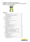
1
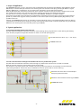
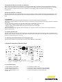
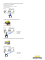
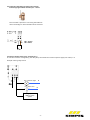
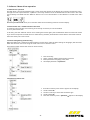
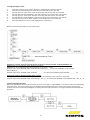
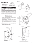
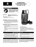
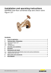
Installation and operating instructions
KEMPER KHS-Timer-Set
Figure 686 08 and Figure 686 09
or
optional
KEMPER KHS-Timer
Figure 686 02 012
KEMPER-KHS-VAV Maximum flow
isolating ball valve
(with servo drive or spring-reset servo
drive Figure 686 04 or 686 05)
-1-
KHS-drain with
overflow monitor
Figure 688 00
Table of Contents
1. Scope of application…………………………………………………………………………………………………………………… P. 3
2. Typical applications………………………………………………………………………………………………………….……....... P. 3
2.1 Protecting a building with the KHS-Timer-Set ..…………………………………..…….…………………………….. P. 3
2.2 Time-controlled water exchange with the KHS-Timer-Set in a potable water system …….………………….… P. 3
3. Description KEMPER KHS-Timer-Set……………………………………………………………………………..…………………...P. 4
3.1 Properties………………………………………………………………………………………………………………..........P. 4
3.2 Function, software…………………………………………………………………………………………………………..P. 4
3.3 Operating modes…………………………………………………………………………………………………………….P. 4
4 .Safety……………………………………………………………………………………………………………………………………...P. 4
4.1 Safety information…………………………………………………………………………………………………………..P. 4
4.2 Hazards if the safety instructions are not complied with……………………………………………………………..P. 4
4.3 Unauthorized alteration and spare part fabrication…………………………………………………………………..P. 5
4.4 Unauthorised modes of operation………………………………………….…………………………………………….P. 5
5. Installation………………………………………………………………………………………………………………………………..P. 5
5.1. Installing the leak controller………………………………………………………………………………………………P. 5
5.2. Mounting the KHS-VAV Maximum flow isolating ball valve………………………………………………………..P. 5
6. Electrical connection of leak controller, additional connection variants for operational cases…………..……………….P. 5
6.1 Terminal description………………………………………………………………………………………………………..P. 5
6.2 Power supply connection…………………………………………………………………………………………………..P. 6
6.3 VAV connection with servodrive………………………………………………………………………………………….P. 6
6.4 VAV connection with spring-reset servodrive………………………………….……………………………………....P. 6
6.5 Connecting the KHS-Free drain as per DIN EN 1717 with ……………………………………………………...…….P. 7
6.6 Example, using a floating alarm relay…………………………………………………………………..…………….....P. 7
7. Software / Menu driven operation…………………………..…………………………………………………………………..….P. 8
7.1 Menu driven operation…………………………………………………………………………..………………………..P. 8
7.2 Performance test / manual function of the valve..……………………………………………………………………………....P. 8
7.3 Initial setting during commissioning..……………………………………………………………………………………………..P. 8
7.4 Setting servodrive type………………………………………………………………………………………………………………P. 8
7.5 Programming the timer………………………………………………………………………………………………………………P. 9
7.6 Alarm acknowledgement…………………………………………………………………………………………………………….P. 9
7.7 Overview of flow chart………………………………………………………………………………………………………………P. 10
8. KHS-Timer dimensions……..………………………….…………………….………………………………………………………..P. 11
9. Materials………………………………………….…………………………………………………………………………………......P. 11
10. Accessories……………………………………………………………………………………………………………………….........P. 11
-2-
1. Scope of application
The KEMPER KHS-Timer as a set in association with the KHS-VAV with servodrive (Figure 686 06 = Figure 686 04 + Figure
686 02 012) or the KHS-VAV plus maximum flow isolating ball with servodrive and spring reset (Figure 686 07 = Figure
686 05 + 686 02 012), is intended for use in potable water installations for the KHS Hygiene System.
With the KHS-Timer-Set, the flushing valve being used is opened / closed according to a preset, individual time interval.
The potable water system is thus put through a water exchange according to the preset opening times.
The goal here is to maintain operation as intended (s. DIN 1988-200, VDI 6023) in the PWC and PWH.
That means the potable water withdrawal is implemented as calculated and as planned to guarantee the requirements
placed on potable water hygiene and the parameters in the TrinkwV (2011 version) (Water Quality Regulation) in the
potable water lines.
Likewise, the KEMPER KHS-Timer set can be used as a terminal flushing valve in non-flooded potable water lines. During
a power failure and simultaneous flushing, the valve automatically closes (closed currentless; applicable only to KHS-VAV
Maximum flow isolating ball valve with spring reset Figure 686 05).
2. Typical applications
2.1 Protecting a building with the KHS-Timer-Set
The KHS-Timer-Set facilitates automatic protection of the building during long absences or when leaving the building.
It has 16 timer programs as adjustment facilities for water cut-off and opening times.
2
1 KHS-VAV with servo drive (1 pc – max. 10 pc.)
2 KEMPER KHS-Timer
1
1
1
2.3 Time-controlled water exchange with the KHS-Timer-Set in a potable water system
The KHS-Timer-Set facilitates automatic water exchange in potable water lines that are not used as intended.
With the 16 timer programs, various flushing times can be stored.
The facility for connecting a drain with overflow monitoring makes it possible to automatically close the KHS-VAV
valve during a backflow. At the same time, the KHS-Timer issues an optical and an acoustic warning.
3
1 KHS-VAV with servo-drive or KHS-VAV-plus
with spring-reset servo drive
2 KHS-drain with overflow monitor Figure 688 00
3 KEMPER KHS-Timer
1
2
-3-
3. Description of the KEMPER KHS-Timer
3.1 Properties / Technical data
•
Microprocessor-controlled device, specifically developed for leak monitoring
•
Surface mounted housing 160x79x58 for wall installation with cable seal plugs
•
Degree of protection IP54
•
Internal consumption: 3 VA
•
Power supply: 230 V/1/N/PE/50Hz/max.3.15 A
•
LCD display 1x16
•
Control on the unit: with 3 buttons up/down, OK, manual
•
LED display: Ready for operation
•
Ambient temperature range: 0°C - 50°C
•
Humidity: 0-90% non-condensing
•
Acoustic alarm (can be switched off)
•
Reset function of the alarm hold: acknowledge on unit
•
Real-time clock with adjustable day and week programs, automatic switchover between daylight savings standard time
•
Screwless cable terminals with operating lever
•
Manual valve operation on device
•
Relay valve switching capacity: Max. 2A AC 1 / 230 V
•
Floating alarm relay: Max. 230 V, 2 A
•
Max. line fuse: 16 A
•
Potential number of KHS-VAV based on Illustration 2.2 (Item 1): 1 to 10 each parallel operated via electrical
subdistributor
3.2 Function, software
•
The software queries the drain and switch inputs, controls the relay, reads and sets the realtime clock
•
Menu driven operation in German, English and Dutch
3.3 Operating modes
The flush and protect operating modes do not have to be set separately. The user selects the operating mode by
positioning the valve at the corresponding point and by setting the timer for his desired operating mode.
A flushing example: Valve installed terminally, Timer Mo., We., Fr. at 6 am open and at 6.05 am closed.
A protection example: Valve at the PW inlet of the area to be protected/Timer Mo. to Fr. open at 6 am, closed at 6 pm.
4. Safety
The descriptions and instructions in these operating instructions cover the KHS-Timer and its facilities for additional
applications.
The prerequisite for operating the controller is the deployment of professionally trained personnel (see EN 50 110-1,
in the ELT sector as well as potable water installations in accordance with TRWI DIN 1988).
If you cannot find all required information and instructions in these operating instructions, please ask the manufacturer,
Gebr. Kemper (see last page for address) to be able to exclude any malfunctions.
If the operating instructions are not followed, the manufacturer of the KHS-Timer does not bear any
responsibility/warrant any guarantee. This operating instructions contain basic instructions that must be complied with
during set-up, commissioning and maintenance. Therefore, the plumber/mechanic and the responsible
specialists/operators must read these operating instructions before assembly, installation and commissioning.
Chapters 1 to 7 must be thoroughly read to ensure the reliability of the KHS-Timer.
4.1 Safety instructions
Before commissioning, make sure the potable water and electrical installation has been made professionally:
- The connections were made properly and professionally and
- The plant is properly protected.
Follow all applicable regulations (ELT, SAN...) and the regulations from the local utilities.
4.2 Hazards if the safety instructions are not complied with
Non-compliance with the safety instructions can lead to both hazards to people and hazards to the environment and
plants as the consequence. Non-compliance with the safety instructions leads to the loss of rights to all compensation
claims. In some cases, non-compliance can, for example, result in the following hazards:
- Failure of important functions in the device.
- Failure of the leak monitoring,
- Hazards to people through electrical and mechanical actions.
-4-
4.3 Unauthorized alteration and spare part fabrication
Alternations and modifications to the device are only permissible after consultation with the manufacturer. Genuine
spare parts and accessories authorized by the manufacturer serve safety. The use of self-procured electronic or potable
water installation components can result in invalidation of the liability of the manufacturer for the resulting
consequences.
4.4 Unauthorised modes of operation
The operational safety of the supplied device is only ensured when used as intended. The deployment/application areas
and limits stated in the documentation (see Technical Data Chapters 3 and 4) must never be departed/exceeded in any
cases.
5. Installation
ATTENTION: Only allow certified specialised plumbers to install and mount electrical equipment.
Very strong magnetic fields can impair the functioning. Interference can be prevented by complying with the installation
rules below:
- Do not mount the controller near inductive loads (motors, transformers, contactors, etc.).
- Feed through a separate mains voltage circuit (if necessary, with mains filter).
- Inductive loads must be equipped with protective devices to reduce overloads
(varistors, RC filter).
When using the controller together with other devices in one system, check to see whether that causes interference
signals to be emitted.
5.1. Installing the KHS-Timer
The leak controller is intended for wall installation. The housing has 4 each ø 4 mm mounting holes in a clearance of w =
148 mm and h = 50 mm. To mount the cover, open the device and screw tightly to the wall. After mounting the housing,
make the required electrical connections.
5.2. Mounting the KHS-VAV Maximum flow isolating ball valves
See separate installation and operating instructions, Figure 686 04 or Figure 686 05.
6. Electrical connection of the KHS Timer:
max.
1 2
3 4 5
6
7 8
9
6.1 Terminal description:
1. Valve switching output 230 V
2. Valve voltage output 230 V
3. Power supply (supply line - L1
4. Power supply (supply line - N
5. Valve - N
6.
7.
8.
9.
Grounded conductor - PE
Drain float switch (conductors interchangeable)
Drain float switch (conductors interchangeable)
Alarm relay (floating contact) 230 V / 2A
-5-
6.2 Connection of power supply terminals Item (L1), (N), (PE):
Power supply: 230 V AC 50/60 Hz
Absorbed power: ca. 3 VA
Connection: Screwless terminals, L1, N, PE
Line fuse max. 16A
L1/230V
N
PE
6.3 VAV connection with servodrive Figure 686 04
Terminal pos. 1, 2 and 5
BN
BK
BU
BN = brown
BK = black
BU = blue
6.4 VAV connection with spring-reset servo drive Figure 686 05
Terminal pos. 1 and 5
BN
BU
BN = brown
BU = blue
-6-
6.5 Connecting the KHS-Free drain with overflow
monitoring Figure 688 00 Terminal pos. 7 and 8
The controller is preset for connecting the KHS-Free
drain. The bridge on Terminal IN3 must be removed.
WS
BN
BN = brown
WS = white
6.6 Using a floating alarm relay, terminal pos. 9
In case of an alarm or voltage drop, the relay drops and switches an external power supply max. 230 V, 2 A
Example: Closing relay version
E.g. indicator light
E.g. alarm horn
N
N
e.g. Input
BMS or alarm
system
-7-
7. Software / Menu driven operation
7.1 Menu driven operation
The KHS-Timer is set and operated through a main menu that appears in the display. The operator accesses the menu
through the control panel with the "Up/Down" arrow keys. Entries can be confirmed with the "OK" button. The valve
can be directly controlled with the "Manual" button if it is not in the submenu. In the submenus it is used as the "ESC"
key.
If no entry is made for ca. 3. min, the controller reverts from the setting mode to the main display.
7.2 Performance test / manual function of the valve
To make sure that the valve is functioning and correctly connected, it is recommended
to run a performance test.
To do that, press the "Manual" button once. Pressing the button again puts the KHS Timer back into automatic mode.
If you want to keep manual mode and not revert back by accident, the KHS Timer reverts back to automatic mode at
thee next switch point of the timer.
7.3 Initial setting during commissioning
When the KHS Timer is used and commissioned for the first time, make the basic settings for language, date and time.
After that the timer can be set using the timer menu item in the main menu.
Initial setting (after starting the menu for the first time)
1.
2.
3.
4.
Press arrow key
Query: Confirm „Make initial settings“ with OK
Enter parameters: Language, time, date
The display indicates > Operation<
1.
Press the arrow key until "Drive" appears in the display
2.
3.
Confirm with OK.
Use the arrow key to select the servodrive type.
4.
5.
Confirm with OK.
Press the arrow key until > Operation < appears in the display.
7.4 Setting servodrive type
-8-
7.5 Programming the timer
1.
2.
3.
4.
5.
6.
7.
8.
Press the arrow key until "Timer" appears in the display and confirm with OK.
Choose the corresponding timer with the arrow key and confirm with OK.
Set each point of "Open time" with the arrow key and confirm each one with OK.
Set each desired "Open Weekday" with the arrow key and confirm each one with OK.
Set each point of "Close time" with the arrow key and confirm each one with OK.
Set each desired "Close Weekday" with the arrow key and confirm each one with OK.
Press the arrow key until "Back" appears in the display and confirm with OK.
Press the up/down arrow key until display shows > Operation <.
Please use the same procedure for the other timers.
Example for settings: Protection during absence for doctor's offices, business, company buildings, etc.
Weekday Mo - Fr: Cut-off time: 8 pm, Opening time 8 am
Weekend Sa - Su: protected except during cleaning on Sa 10 am – 12 pm
Timer01 / Open time: 08:00:00 / Open weekday: Mo,Tu,We,Th,Fr,_ _ / Close time: 20:00:00 / Close weekday:
Mo,Tu,We,Th,Fr,_ _
Timer02 / Open time: 10:00:00 / Open weekday: _ _ _ _ _ _ Sa / Close time:12:00:00 / Close weekday: _ _ _ _ _ _ Sa
Example for settings: Flushing potable water systems
Flushing should be undertaken weekdays on Mo, We, Fr and Saturday, each at 8 am for 5 minutes.
Timer01 / Open time: 08:00:00 / Open weekday: Mo _ We_ Fr _ Sa / Close time: 08:05:00 / Close weekday: Mo _ We_ Fr _ Sa
7.6 Acknowledging the alarm
When the float switch floats up the controller goes into "Free drain", Figure 688 00, in the alarm mode and immediately
closes the valve. The alarm buzzer can be immediately acknowledged; the valve remains closed. After repairing the
problem, the alarm can be acknowledged by enabling the valve. The controller is once again operational with all preset
programs.
-9-
7.7 Overview of flow chart
8. KHS-Timer dimensions
9. Materials
Materials
Controller housing
ABS
10. Accessories
Optionally available accessories
Insulating shells for maximum flow isolating ball valve
Figure 471 19
KHS-VAV with servodrive 230 V Figure 686 04
Figure 686 04
KHS-VAV with spring-reset servo drive 230 V
Figure 686 05
KHS-drain with overflow monitor
Figure 688 00
Gebr. Kemper GmbH + Co. KG, Metallwerke
Harkortstr. 5, D-57462 Olpe
Tel. 0 27 61 - 8 91 - 0, Fax 0 27 61 - 8 91 -1 75
[email protected], www.kemper-olpe.de
K410068602012-00 02/13
Technical subject to change.
- 10 -