1
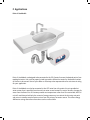
ECCOTEMP Point of Use Tankless Water Heaters EP-2.4 / EP-7.0 Installation and Operating Instruction Manual Product Support Shop Online Store Locator Eccotemp.com/help-desk Eccotemp.com/products Eccotemp.com/locator 866-356-1992 [email protected] 315-A Industrial Road, Summerville, SC 29483 E L E C T R I C TANK LES S PO INT OF US E WATER HE ATE R I N STA L L AT I ON GU IDE & OW NE R S MA NUA L This manual is provided as a guide to installation. All installations must comply with any and all local and national electrical and plumbing codes. Warranty of this heater will depend on proper installation and operation. The manufacturer will not be liable if the heater has been modified in any way or the installation and operating instructions outlined in the following pages have not been followed in their entirety. Your Eccotemp water heater can be serviced by most heating, plumbing or HVAC repair centers in your area. If your preferred service center does not already have Eccotemp service information, Eccotemp will promptly provide the necessary information to the service center on request. For information regarding service companies in your area, please contact your original installer or Eccotemp. Eccotemp Systems, LLC 315-A Industrial Rd. Summerville, SC 29483 866-356-1992 [email protected] If you have any questions regarding the installation or performance of this heater, please call Eccotemp’s customer service department and provide the information listed below: Model: Serial Number: Install Date: ANY RETURNS AUTHORIZED BY Eccotemp MUST HAVE A VALID RETURN MERCHANDISE AUTHORIZATION NUMBER CLEARLY VISIBLE ON THE PACKAGE. ALL OTHER SHIPMENTS WILL BE REFUSED. BE SURE TO RETURN THE PACKAGE TO THE ADDRESS LISTED ON THE AUTHORIZATION A. MO UNTI NG TH E U NIT The unit m ust be mounted leve l o n t he wa ll ( o r wi t h t he wa t e r f i t t i n gs u p t o 3° hi gher in the vertical pos i t i o n ) . B e s u re t o a llow a d e qu a t e cle a ra nce a nd p roper or ientation for field wi ri n g i nst a lla t i o n a nd i ns pe ct i o n . It ca n o n ly be mounted in one of four poss i b le o ri e nt a t i o ns a s s hown i n t he d i a gra m be low. The water fitting s m ust be a t t he t o p whe n mo u nt e d ve rt i ca lly o r t owa rd t he t op left or top r ig ht when mo u nt e d ho ri z o nt a lly wi t h t he wo rd E CCOTE M P r i g ht si d e up on the cover. FA I LURE TO FOLLOW THESE I NSTRU CTI O NS W I L L RESU LT I N SERI O U S DA M AG E TO T H E UNIT 1. T he cold-water inlet and hot -w a t e r o u t le t a re cle a rly m a rke d a nd m ust not be rever sed. 2 . T he heater should be fa st e ne d t o t he wa ll u s i n g t he i nclu d e d mounting br acket. Remove t he b ra cke t fro m t he he a t e r a nd s e cu re i t to a solid wall sur fa ce. B e s u re t he b ra cke t i s leve l a nd i n t he proper or ientation. If mo u nt i n g t o a ho llow wa ll, ca re s ho u ld be taken to locate a stud o r t o u s e a p p ro p ri a t e ho llow wa ll a ncho rs. After mounting the bra cke t , s li d e t he u n i t o nt o t he b ra cke t a nd replace the screws to s e cu re t he u n i t t o t he b ra cke t . 3. Never solder water sup p ly li ne s t o t he he a t e r’s f i t t i n gs. He a t fro m solder ing m ay dam age t he o ne - p i e ce f i t t i n gs a nd t a n k. Do not u s e Plum ber ’s Putty or PVC/ CPVC p ri me r a nd glu e o n t he t h re a d s of the heater’s inlet and o u t le t f i t t n gs. T he s e p rod u ct s m ay d i ss o lve the threads on the hea t e r’s f i t t n gs ca u s i n g pe rm a ne nt d a m a ge a nd/ or leaks. Teflon tape is t he o n ly s e a le r t h a t s ho u ld be u s e d o n t he threads of the fitting s o r i nclu d e d a d a pt e rs. 4 . O pen the valve on any ne a rby s i n k a llowi n g wa t e r t o ru n fo r a couple of m inutes to e ns u re t h a t a ll a i r i s p u rge d fro m t he u n i t . 5. T & P Valve/Anti-scald Devi ce: N a t i o n a l cod e s d o not re qu i re t he i nstallation of these d evi ce s. Co ns u lt loca l cod e s fo r re qu i re me nt s for exter nal T &P or Ant i -Sca ld d evi ce s. B. PLUMB I NG H OO K- UP 1. The unit is supplied with 3/4 ” N PT f i t t i n gs mo ld e d i nt o t he he a t i n g c hamber. DO NOT U SE PIPE DO PE O R PVC PR IMER O R GLUE O N T HE F I TTI NG S. DO NOT U SE A TO RCH O N A N Y FIT T IN G CO N N ECTED TO T H E HE ATE R. U se only TEFLO N TAPE o n t he t h re a d s e ns u ri n g t h a t no t a pe o r d eb ri s enter s the heater. 2 . If an adapter is req uired to re d u ce f i t t i n g s i z e, u s e t he e nclos e d a d a pt e r w i t h O-r ing. No additional sea la nt s o r t e f lo n t a pe i s re qu i re d . Fo r ot he r ad apt ers, be sure to use 3/4 N PT f i t t i n gs a nd s e a l wi t h TEFLO N TA PE ONLY. Connect plum bing to t he a d a pt e rs wi t h t e f lo n t a pe. 3. 3. F lex-pipe is recom mended fo r e a s e of i nst a lla Io n a nd s e rvi ce. Whe re fi xed p ipe is used, a plum bin g u n i o n i s re co m me nd e d fo r e a s e of s e rvi ce. 4 . Always use two wrenches to t i ght e n p lu m b i n g f i t t i n gs t o t he he a t e r t o avoi d stress to the fitting s a nd he a t i n g ch a m be r. 5. Inst al l ball valves on the inlet a nd o u t le t p i pe s t o a llow i s o la t i o n of t he heat er for ser vice. Be sure bot h va lve s a re o pe n p ri o r t o a ct i va t i n g t he heat er. 6 . Recommended operating pre ss u re i s 60 t o 8 0 PS I. Fo r i nst a lla t i o ns wi th hi gher pressure a PRV is req u i re d . Fo r i nst a lla t i o ns a bove t he ce i li n g o r at t i c , a bleed air separ ator is re co m me nd e d . Whe re wa t e r h a m me r e x i st s, a p roper ly sized arrestor sho u ld be i nst a lle d . 7. R un water throug h the unit fo r a few m i n u t e s u nt i l a ll vi s i b le a i r i s p u rge d from t he lines and unit and t he f low i s co nt i n u o u s wi t ho u t s p i t t i n g a i r. N OTE : A LL PLUMBING M U ST BE COM PLETED B EFOR E STA R TI N G ELECTR I CA L H O O KU P TE ST AL L CONNECT IONS FOR LEA KS B EFOR E CON N EC TI N G ELEC TR I CI TY C . COM MI SSI O NI NG TH E UNIT 1. Open a ll ball valves and turn o n wa t e r o u t le t s. 2 . Ac t i vate power at breaker. 3. C yc le the water on and off a nd ve ri f y u n i t o pe ra t i o n . 4 . Veri fy tem perature and adjust a s ne ce ss a ry. 5. If d esi red tem perature is not re a che d , ve ri f y f low a nd s i z i n g i nforma tion to ensure adeq u a t e ly s i z e d u n i t h a s be e n i nst a lle d . D. ELECTR I CAL H OOK - UP 1. Wire entr y into the uni t s ho u ld be m ade throug h the knocko u t i n t he bottom of the cover. 2 . Cover End Cap m ust be re move d to allow installation and i ns pe ct i o n of proper wir ing. (Veri f y co rre ct i nstallation in accorda nce wi t h diag ram on page 2 of t h i s m a n u a l pr ior to wiring unit for p ro pe r oper ation). 3. Proper connectors sho u ld be chos e n for the wire/conduit se le ct e d . 4 . Connect properly sized co p pe r le a d s to the ter m inal block a s s hown . 5. Connect the power circ u i t s t o L 1 a nd L2 as shown and the gro u nd t o GN D. (For 1 20V models conne ct t he N e u t ra l to L2/N on the term ina l b lock) . PRE-POWER CH ECK: 1. Ver ify that all connecti o ns a re s e cu re. 2 . Ver ify that an adeq uat e gro u nd h a s been properly connect e d . 3. Ver ify that adeq uate s i z e d b re a ke rs have been properly co n ne ct e d . Remem ber that breake rs t h a t a re too large are more dan ge ro u s t h a t breakers that are too s m a ll. 4 . Ver ify proper wire size h a s be e n u s e d for connection. 5. Check voltage at the te rm i n a l b lock for each circuit. THIS INSTALLATION MUST BE DONE BY A QUALIFIED AND LICENSED CONTRACTOR. Refer to your local electric and plumbing codes for additional information. VERIFY PROPER INSTALLATION PRIOR TO WIRING UNIT (SEE DIAGRAM ON PAGE 2) E. Limited Warranty Eccotemp Systems, LLC, hereinafter Eccotemp, warrants the Chamber Body and Heating Element of its tankless water heaters against defects in materials and workmanship for a period of three years. The Chamber Body and Heating Element as referred to herein shall mean the plastic body of the heat exchanger and the standard immersion heat element itself, and does not include component parts attached to them. Eccotemp warrants the Circuit Board and other Electronic Components to be free of defects in materials and workmanship for a period of eighteen (18) months. All other parts are warranted for a period of one (1) year. This warranty begins on the date of retail purchase or, in the absence of proof of purchase, from the date of manufacture. Circuit Board or Chamber Body replacements to the original purchaser, made after the initial warranty expires and not later than five years will be replaced by Eccotemp, subject to replacement charges not to exceed 25% of the current manufacturer’s suggested retail price of the unit model for which it was originally installed, or a currently sold comparable unit. Shipping charges are not included. Eccotemp reserves the right to use remanufactured parts when repair becomes necessary. When advance shipping of replacements are requested, Eccotemp may require a deposit until the failed items are returned and inspected for warranty coverage. This warranty does not cover the cost of any shipping or labor charges. EXCLUSIONS AND LIMITATIONS OF THESE LIMITED WARRANTIES THE LIMITED WARRANTIES PROVIDED HEREIN ARE IN LIEU OF ANY AND ALL WARRANTIES, EXPRESSED OR IMPLIED, INCLUDING BUT NOT LIMITED TO IMPLIED WARRANTIES OF MERCHANTABILITY AND THE FITNESS FOR A PARTICULAR PURPOSE; PROVIDED, HOWEVER, THAT IMPLIED WARRANTIES ARE NOT DISCLAIMED DURING THE ONE YEAR PERIOD FROM THE DATE OF ORIGINAL RETAIL PURCHASE. Eccotemp SHALL HAVE NO LIABILITY HEREUNDER EITHER DIRECT OR CONTINGENT, FOR INCIDENTAL OR CONSEQUENTIAL DAMAGES. SOME STATES DO NOT ALLOW THE EXCLUSION OR LIMITATION OF INCIDENTAL OR CONSEQUENTIAL DAMAGES, SO THE ABOVE LIMITATION OR EXCLUSION MAY NOT APPLY TO YOU. This warranty gives you specific legal rights, and you may have other rights THAT vary from state to state. These warranties shall be void and have no effect: 1. If the Eccotemp heater is not used for its intended application; 2. If the design or structure of the Eccotemp heater is modified or altered in any way; 3. If appliances or equipment not approved by Eccotemp are attached to the water heater; 4. If the water heater is not property installed in compliance with the latest issue of (1) the National Electric Code, (2) the applicable plumbing codes, (3) all local ordinances and regulations pertinent to similar water heaters, and (4) the installation guide and operational manual provided with the Eccotemp water heater; 5. If the Eccotemp water heater is installed upside-down, or is not protected from freezing; 6. If the Eccotemp water heater is not operated within the factory calibrated temperature limits; 7. If leaks or defects arise as the result of improper use, improper installation, negligence in operation, failures resulIng from accident, or from inability of the Eccotemp water heater or any parts to function because of improperly made replacements and repairs, or damage by fire, floods, lightning, or any other act of God; 8. If the plumbing design allows water to flow in reverse through the Eccotemp heater; 9. If the Eccotemp heating element(s) fail due to air entrapment; 10. If the serial number has been altered or has become illegible; 11. If the Eccotemp heater is installed in any area where leakage of the tank or connections would result in property damage of any kind, or where such a location is unavoidable, a suitable drain pan was not installed under thewater heater. (When a drain pan must be used, the pan must meet all applicable plumbing codes and be at least 2 1/2”deep, extending not less than 1” above the unit’s base plates, must protect an area at least 1-1/2” greaterthan the lower external dimensions of the heater, and must be piped by a minimum 1” pipe to an adequate drain; 12. If the Eccotemp heater or any of its components warranted herein are used other than as a part of the complete and integrated system as sold to the original purchaser; 13. If leaks in the tank or defects in other parts occur as a result of the Eccotemp heater containing or being operated with de-ionized water; 14. If leaks in the tank or defects in other parts arise as a result of sizing that does not comply with the manufacturer’s currently published sizing recommendations; Replacements and/or repairs furnished under this warranty carry only the unexpired portion of the original warranty or 90 days whichever is longer. The terms of this warranty may not be varied by anyone, whether or not purporting to represent or act on behalf of Eccotemp. F. Applications Point of Use Models Point of Use Models are designed to be connected to the COLD water line near the desired point of use needing hot water. Unit must be properly sized to provide sufficient hot water for the desired number of fixtures to be served. Contact your dealer or Eccotemp sales representative for assistance in sizing for your application. Point of Use Models can also be connected to the HOT water line at the point of use to provide hot water sooner than is possible from the main hot water source located in a central location a longer distance from the fixture. As all Eccotemp models are temperature rather than flow controlled, the POU unit will modulate and add only the amount of energy necessary to maintain the hot water set point and return to standby once hot water arrives from the primary hot water source. This offers energy AND water savings over other alternatives such as recirculation. TROUBLESHOOTING The Eccotemp microprocessor control depends on the temperature information it receives from each of the temperature sensors to detect water flow and maintain proper temperature. If any sensor or its connection to the circuit board is bad, the Eccotemp may not turn on at all or if it does the temperature may fluctuate. Whenever servicing a Eccotemp, the proper operation of the sensors and the circuit board should always be verified regardless of the trouble code. Eccotemp recommends you follow the pre-service checklist every time you service the unit to verify proper operation. PRE-SERVICE CHECKLIST: • Verify Installation: • Verify proper plumbing, cold to the inlet and hot to the outlet. • Verify flow rate matches the specifications of the unit. • Verify the heater is mounted properly and level. INLET NIPPLES ARE ALWAYS AT THE TOP OF THE UNIT WHETHER MOUNTED HORIZONTAL OR VERTICAL. • Record the serial number in the event you need to contact Eccotemp Customer Service. Tests with Power OFF • Verify water flow through the heater. Check that shut off valves are in the open position. • Check the plumbing and the unit for any signs of leaks. • Check for any loose wires to the circuit board and verify the power connections are tight. If stranded wire is used, check that all strands are inside the lug. • Tests with Power ON • Verify circuit breakers are turned on and verify power to the heater. Check the voltage at the terminal block. • Check the circuit board LED for any diagnostic codes. Visit http://www.eccotemp.com or contact customer service for latest diagnostic code information. HEATER TESTING – TEST WITH POWER OFF AND METER SET TO MEASURE RESISTANCE COMPONENT EXPECTED RESULTS Temperature sensors Readings should be taken after the heater has been cooled down so that the temperature in the chamber is uniform. (Run water with power off for 3-5 minutes) All sensor resistance measurements should be within 10% of the others. Heating Elements Read across screws at the Red & Black wires. Typical readings are in the range of 5 to 14 ohms but vary with wattage and voltage. Moisture Detect Switch Should normally read open. If closed, check for water leaks or water on the switch pad. Correct the leak, dry the switch and retest. POWER ON TESTS (SHOULD ONLY BE PERFORMED BY A QUALIFIED TECHNICIAN) COMPONENT TEST EXPECTED RESULTS Incoming Power Lugs Voltage L1 to L2: 208-277 VAC depending on model; L1 to Neutral 110- 120 VAC (for 120V models). Heating Element Amps Measure Amps on wires leading to element with water flowing, Maximum reading at full power calculated as Watts/Volts. ECCOTEMP Point of Use Tankless Water Heaters EP-2.4 / EP-7.0 Installation and Operating Instruction Manual Product Support Shop Online Store Locator Eccotemp.com/help-desk Eccotemp.com/products Eccotemp.com/locator 866-356-1992 [email protected] 315-A Industrial Road, Summerville, SC 29483