1
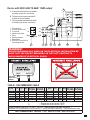
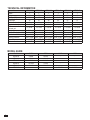
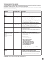
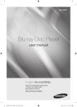
Hot Water on Demand
InLine
900 Series
Directions of Assembly and Operation of “In-Line” Instant Water Heater
“Instant” appliance is a novel device designed to supply hot water instantaneously upon
demand while conserving electricity, water and energy.
The “In-Line” is the most advanced heater in the “Instant” family and as such can be installed
anywhere, and serve any purpose. When the flow switch turns on the electrical current, the
heating element heats only the amount of water economically needed for use.
OVERVIEW
This manual must be read carefully before attempting to install the water heater. If you do not follow the
safety rules or the instructions outlined in this manual, the unit may not operate properly and it could cause
property damage, serious bodily injury or death.
Atmor will not be liable for any damages because of failure to comply with the installation and operating
instructions outlined in this manual or because of improper use. Improper use includes the use of this
appliance to heat any liquid other than water. Failure to comply with the installation and operating instructions
or improper use voids the warranty. Never remove the unit’s cover unless the electricity is turned off.
SAFETY PRECAUTIONS
Please read and follow these instructions. Failure to follow these instructions could result in serious bodily
injury or death.
The unit must be installed by a licensed electrician / plumber. The installation must comply with all national,
state and local plumbing and electrical codes.
Service of the unit must be performed by qualified service technicians.
Before proceeding with any installation, adjustment, alteration, or service of this unit, all circuit breakers and
disconnect switches servicing the unit must be turned off. Failure to do so could result in serious personal
injury or death.
Danger: Never remove the unit cover unless the electricity servicing the unit is turned off. Failure to do so
could result in personal injury or death.
Warning: The unit must be properly grounded. Failure to electrically ground the product could result in
serious personal injury or death.
Warning: Unit must be installed with the plumbing connections pointing downward only.
Warning: Do not install unit where it would routinely be splashed with water. Electric shock or death may
result.
NOTE: If soldering near the unit is necessary, please direct the flame away from the housing of
the unit, in order to avoid damage. Excessive heat from soldering on copper pipes near the unit
may cause damage. All plumbing work must comply with national and applicable state and local
plumbing codes.
2
INSTALLATION INSTRUCTIONS
This water heater must be installed by a licensed electrician, as required by law.
1. Open the four screws located on the top and bottom of the device and remove the cover from base.
2. Fix the base horizontally against a wall or side of cabinet, metal plate supplied must be installed
below cable entry on the wall and ground wire must be connected to the unit, the water entry and
exit connectors are on the down/bottom side of the unit. Use 4 mounting screws provided.
3. For the AT900-13 model, use the supplied water filter on the income water line (see attached separate
diagram: "Water filter installation").
4. Connect the incoming water line (cold only) on the bottom left side and the outgoing water line to the
bottom right side. Please check that there is no water leakage from the unit.
5. Connect and lock the electric lines to each corresponding connector. It is required that this device be
properly grounded.
6. Turn on the unit and check that it is operating as required.
7. Reconnect the cover to the base with 4 screws.
8. It is required that a Ground Fault Circuit Interrupter/Earth Leakage Circuit Breaker be incorporated in the
circuit.
9. Make sure that there is a pressure release valve in your water system.
10.It is required to install a flow control restrictor (AERATOR) at the sink or shower.
WARNING: UNIT MUST BE PROPERLY GROUNDED
THIS HEATER MUST HAVE ITS OWN INDEPENDENT CIRCUIT USING
A CORRECTLY RATED CIRCUIT BREAKER AND SUITABLE WIRE, SEE
TABLE RECOMMENDED CABLE.
3
OPERATION INSTRUCTIONS
1. Your new Instant Water Heater is flow activated. Simply place one or both switches in the ON position
and turn on the hot water tap. You will need to allow at least 1.5 liters per minute to flow through the unit
in order to activate the Instant Heating System. Run water through the heater for a few minutes.
2. Be sure to every so often clean the spray head of sediment to assure a smooth water flow.
3. Be sure to every so often clean the incoming water filter.
4. The maximum operating water pressure is 8 atmospheres or 115 PSI. This is well above the usual 3
atmospheres or 40 PSI most municipal water systems provide.
5. Be sure to install your Instant Water Heater in a heated location. It cannot be installed where temperatures
drop below freezing.
6. There are two ways to adjust the hot water temperature. One is by adjusting the flow, the other is by
changing the electrical settings on the unit. The slower the flow, the more time the unit has to heat the
water, resulting in higher water temperatures. Adding more rings to the water flow restrictor will limit the
flow and increase the output water temperature. You may choose the low, medium or high settings on
the heater, as required to achieve the water temperature desired.
Setting 0/OFF: No heating, lamp will not light.
Setting 1: Low heating, lamp 1 will light.
Setting 2: Medium heating, lamp 2 will light.
Setting 3: Maximum heating, both lamps will light.
For 220V - 240V 3.5kW unit only positions 0 & 1 are available.
7. During the summer, it is recommended using only setting 1 or 2 for device with 220V-240V 13kW output.
INSTALLATION REQUIREMENTS
A. A separate electrical line is required.
B. The device must be connected to a separate circuit breaker.
C. The recommended electrical cable for feeding the device, see table I (next page).
Device below a sink with 110V up to 3.5kW output
and 220V-240V 3.5kW-8.6kW output
1
1
L
E(G)
N
1. Terminal block 2. Thermal cut-out with reset
3. Thermal cut-out
4.Relay
5.Light
6. Switch 0- Off
(Option) 1- Low
7. Heating element
8. Read sensor
L1
E(G)
L2
Device below a sink with 220V - 240V 8.6kW-10.6kW output
1
4
L
N
L1
L2
E(G)
E(G)
1
3 4
8
7
5
6
1. Terminal block
2. Thermal cut-out with reset
3. Thermal Cut out
4.Relay
5. Switch 0- Off
1- Low
2- Medium
3- High
6. Heating element
7. Read sensor
8. EARTH(G) Connection in
the heating canister
Device with 220V-240V 10.6kW- 13kW output
3
A.A separate electrical line is needed
as power supply for this device.
B.The device must be connected to
a separate circuit breaker.
C.The recommanded electrical cable
for feeding the device, see table I.
1. Terminal block
L
2. Thermostat with reset
3.Thermostat
N
4. Switches with lights
E (G)
5.Relay
6. Heating elements
7. Read sensor
8. EARTH(G) Connection in
the heating canister
L1
L2
E (G)
1
1
8
2
7
4
5
6
WARNING!
BEFORE BEGINNING ANY WORK ON THE ELECTRICAL INSTALLATION BE
SURE THAT THE CIRCUIT BREAKER IS IN THE “OFF” POSITION TO
AVOID DANGER OF ELECTRICAL SHOCK
INLET
OUTLET
Inlet and
outlet at the
bottom
TABLE I: RECOMMENDED CABLE
Min Field Min Ground
AMPS Wire
(AWG) Wire (AWG)
Model
V ac
kW
3.0N-110
3.8N-110
120
120
3.5
4.4
30
37
10+
6+
10+
10+
3.5N-220 240
3.8N-220 240
5.5N-220 240
3.5
3.8
5.5
15
16
23
14
12
10
14
12
10
Model
V ac
kW
6.0N-220 240 6.0
6.5N-220 240 6.5
8.5N-220 240 8.5
9.5N-220 240 9.5
10.5N-220 240
10.5
11.0N-220 240
13.0
Min Field Min Ground
AMPS Wire
(AWG) Wire (AWG)
25
27
35
40
44
55
10
10
6
6
6
4#
10
10
10
10
10
8#
Not specified = Cooper wire to be rate min 140 Fº
+
= Cooper wire to be rate min 167 Fº
#
= Cooper wire to be rate min 194 Fº
• Operating water pressure 0.5-10 bar (7-145 psi) • Water pressure operated flow switch
• Standard 1/2"Ø compression inlet connection • Top-left and right cable entry • Bottom-left water entry
UNIT DIMENSIONS: HEIGHT 7.3in WIDTH 11.8in DEPTH 3.55in
5
TECHNICAL INFORMATION
item no.
Phase
Voltage
Wattage (KW)
Amperage
Circuit breaker size
Required wire size (min)
Minimum water flow to
activate unit
Weight (lb)
Dimensions (in) (HxWxD)
Nominal water volume
Working pressure
Texted to pressure
Water connections
AT900-04
1
240
3.8
16
20
12 AWG
AT900-06
1
240
6.5
27
30
10 AWG
AT900-08
1
240
8.5
36
40
6 AWG
AT900-10
1
240
10.5
44
50
6 AWG
AT900-13
1
240
13
55
55
4 AWG
AT900-03
1
110
3
27
30
10 AWG
0.5 GPM
0.5 GPM
0.5 GPM
0.5 GPM
0.5 GPM
0.5 GPM
3.4 lb
7.3x11.8x3.55
0.11gal / 0.42 l
8 bar (115psi)
16 bar (230psi)
1/2" NPT
3.4 lb
7.3x11.8x3.55
0.11gal / 0.42 l
8 bar (115psi)
16 bar (230psi)
1/2" NPT
3.4 lb
7.3x11.8x3.55
0.11gal / 0.42 l
8 bar (115psi)
16 bar (230psi)
1/2" NPT
3.4 lb
7.3x11.8x3.55
0.11gal / 0.42 l
8 bar (115psi)
16 bar (230psi)
1/2" NPT
3.4 lb
7.3x11.8x3.55
0.11gal / 0.42 l
8 bar (115psi)
16 bar (230psi)
1/2" NPT
3.4 lb
7.3x11.8x3.55
0.11gal / 0.42 l
8 bar (115psi)
16 bar (230psi)
1/2" NPT
MODEL GUIDE
Model
AT900-04
AT900-06
AT900-08
AT900-10
AT900-13
AT900-03
6
240V
3.8 kW
6.5 kW
8.5 kW
10.5 kW
13.0 kW
-
208V
2.8 kW
4.9 kW
6.4 kW
7.9 kW
9.8 kW
-
110V
3.0 kW
120V
3.5 kW
TROUBLESHOOTING GUIDE
Your water heater has no internal user serviceable parts and should be returned to the factory for repair or
replacement. Please contact toll - free hot line for return authorization.
If after following the Installation Instructions, your Instant heater does not heat water in accordance with this
literature, please check the following:
Symptom
Possible Cause
Solutions
No hot water despite
fully open hot water
faucet
No electrical power.
Check the circuit breaker and
Voltage at the wiring block.
Low Voltage / Low
Power
Verify your voltage by using a voltage meter. You
should obtain your reading off the
two outside terminals located on the heater.
Compare the reading against the voltage specified
in the Installation Instructions.
The center terminal is always the earth ground.
Length of Pipe
Length of pipe run will affect the temperature
increase. The heater should be mounted
No more that 12-18 inches from the point of use.
Flow Rate
Controlling flow rate is essential to insure proper
temperature increase.
Check your flow rate to insure proper operation of
the heater.
Low flow rate
In the case of the low flow rate heater, it is
mandatory that the flow control be attached to the
end of the faucet.
The activation flow rate
Needed to turn on the
heating
Element has not been
reached
Clean filter screen
- turn circuit breaker off
- open hot Valve to release
Pressure from the unit.
- Check shut-off valve and make
sure valve is open 100% to allow
full water pressure to the heater
- turn circuit breakers on.
Standard Flow Rate Models require 0.5GPM to
activate.
No running water from
the unit
Freezing
Instant heaters must be drained and stored if
installed in a location subject to freezing.
Disconnect the inlet/outlet compression fittings and
blow air through one side of the heater to assist
draining.
• Problems? - Call our toll-free hotline (888) 783-6082 Ext. 311.
7
LIMITED WARRANTY
Atmor warrants to the original owner that our instant water heaters will be free from defects in
workmanship and material for a period of TWO YEARS from the date of purchase, and free from
leakage for a period of SEVEN YEARS from the date of purchase. Should any part(s) prove to be
defective during this period, Atmor will be responsible for replacement of the defective part(s) only.
Atmor is not responsible for labor charges or any incidental or consequential expenses.
Should the owner wish to return the water heater for repair, the owner must first secure a written
authorization from Atmor. The owner shall be required to show proof of purchase date and to pay all
transportation costs to return the defective part(s) or water heater for repair or replacement. Warranty
is void if: (i) water heater has been installed or used improperly; (ii) design has been altered in any way;
(iii) water heater has been installed and/or serviced by someone other than a licensed electrician ; (iv)
or if the water heater has been installed or used in contradiction to installation instructions, applicable
laws and/or ordinances.
Distributed by:
PARAGON GROUP USA - LLC
Englewood, NJ 07631
(201) 266-6775
8
P.N. 115045B
15 Engle Street, 3rd Floor