1
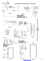
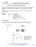
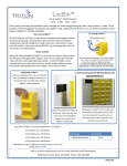
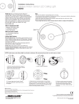
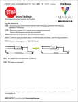
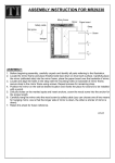
Installation & Assembly Instructions
1785 - Storability® 33"L x 63"H Garage Storage System
Read all instructions completely before installing. Should you have any questions about your installation, please call
Customer Service at 440-248-5480. Missing and damaged parts must be reported within 5 days from receipt of delivery.
Tools needed for this installation (Not Supplied with Kit)
Lever - Pencil or marker - Phillips head screw driver – Electric drill – ½” Standard drill bit for hollow wall installation –
Safety glasses – 5/16” Masonry bit for concrete block installation – 1/16” Standard drill bit for stud wall installation – Tape
measure
Parts Listing
P/N#
Qty
Description
Qty
Hardware______________________
10-01815T
1
Top Track Sections
5
2-1/2” Toggle Bolts
10-0280-1T
2
Top Hang Rail with hanging Slots
6
3-1/2” Toggle Bolts
10-0280-2T
2
Bottom Hang Rail Section
11
White Plastic Wall Anchors
10-0280-3T
2
Hang Rail Connector with 2 bolts
11
2-1/4” Wood Screws
10-0480
1
31” Wire Shelf
11
Toggle Bolt Expanders
10-0336
1 Set
Hanging Brackets for Wire Shelf
1
Hex Head Wrench for Hang Rails
10-0580
1
31” Combination Rail
10
Assorted LocHooks for Tool Board
10-0880
1
LocBoard Tool Board
3
Plastic Hanging Bins
10-1901
1
31” Wire Basket
3
Assorted Combination Rail Hooks
10-2001
1 Set
Hanging Brackets for Wire Basket
We have included all mounting hardware for hollow and concrete block wall installations. It is not necessary to mount system
to wood studs. Each system will require 35 lineal Inches of wall space for mounting and a minimum ceiling height of 7-1/2 feet
high for proper clearance.
Drill Diameter Listing:
Drill diameter sizing for hollow wall installations: Use 1/2” standard drill bit
Drill diameter sizing for concrete wall installations: Use 5/16” masonry drill bit
Drill diameter sizing for wood Stud wall Installations: Use 1/16” standard drill bit for pilot holes
Preparation for Top Track Installation: (Image A-1)
1. When installing in a corner, leave 1” space between side wall and your top track.
2. Determine the maximum height of storage you would like available above your system. (See Fig. A-1). For an 8 foot
ceiling; 78” off the floor leaves 18” of storage above and 81” leaves 15” storage above.
3. Using a tape measure, mark your desired height off the floor with a 4” long pencil mark.
4. (Refer to Fig. A-1 & A-2) Using a level, align top of top track with your pencil mark in step 3. With top track level, mark
the center of each hole’s location on your wall. (Note: Before starting to drill holes always make sure all screw hole
locations do not fall in line with electrical wires, duct work or plumbing inside of your wall. If a potential problem exists,
reposition and remark screw hole locations.)
5. (Fig. A-2) Drill hole locations marked using the correct drill diameter sizing and type listed above. Should you come in
contact with wood studs, stop and mark the hole with X and after drilling all other holes come back and drill these holes
using a 1/16” bit for pilot hole for wood screws.
Attachment of Top Track to Wall Surfaces: (Fig. A-3)
6. For hollow walls; (Fig. A-3) Use 2-1/2” long toggle bolts with expanders. Insert all toggle bolts through top track and
attach all toggle bolt expanders. Omit toggle bolts that fall in line with X or wood studs. Insert toggle bolts with
expanders into holes in wall before starting step 9.
7. For concrete walls; use white plastic wall anchors and 2-1/4” long wood screws. Install all plastic wall anchors in all hole
locations before starting step 9.
Please contact our Customer Service Division with any questions at:
30700 D Carter Street ∙ Solon, OH 44139 ∙ (P) 440.248.5480 ∙ [email protected]
For a full line of products visit www.tritonproducts.com
1
INS3535
Installation & Assembly Instructions
8. For wood studs use 2-1/4” long wood screws. Always install wood screws last and there will be no need to use plastic
wall anchors.
9. Using a level and holding top track in place tighten one of the end toggle bolts or wood screws until snug. (Allow for
track movement).
10. Making sure top track is still level, tighten toggle bolt or install wood screw on the opposite end until fully secure and
then go back and fully tighten the first toggle bolt.
11. Install and fully tighten all remaining toggle bolts or wood screws.
Hang Rail Assembly: (Fig. B-1) Assemble (2) 64”long hang rail assembly consisting of 3 parts, (A) Top Slotted section (B)
Bottom rail section and (C) Hang rail connector with 2 bolts.
Hanging Hang Rails: (Fig. B-2, B-3 and B-4). Note: When installing hang rails, work from left to right or right to left and
always installing one hang rail at a time.
12. (Fig. B-2 and B-3) Slide each hang rail assembly onto front lip of the top track. Position each hang rail at opposite ends
of the track 1/8” (.125”) in from each end.
13. Starting from one end, make sure the top outside edge of the hang rail is no greater than 1/8” away from the outside
vertical straight edge of the top track. Using a level, make sure hang rail is flat against wall surface and straight; while
holding in place mark the centers of the 3 bolt holes locations onto the wall.
14. Drill locations marked in Step 13 using the correct drill bit for your type of wall surface. (Refer to drill diameter listing
above.) Note: Should you come in contact with a wood stud stop drilling and mark hole with an X. After drilling all
other holes come back to the X and using a 1/16” bit, create pilot hole for wood screw installation.
Attaching Hang Rails to Wall Surfaces; (Fig.B-4 thru B-6)
15. Hollow walls: Use 3-1/2” long toggle bolts with expanders. Remove hang rail from top track, and insert toggle bolts
through holes in hang rail and attach all toggle bolt expanders. Re-install hang rail and insert toggle bolts with
expanders into holes in wall before starting step 18.
16. Concrete walls: Use white plastic wall anchors and 2-1/4” long wood screws. Install all plastic wall anchors in holes
before starting step 18.
17. Wood studs: Use 2-1/4” long wood screws.
18. Using a level and keeping hang rail straight, tighten bolts in order 1) top, 2) bottom and 3) center.
Second Hang Rail Attachment: (Fig. B-4 thru B-6)
19. Slide the second hang rail to the opposite end of top track. Inside spacing between hang rails should be 30.25” (301/4”).
20. Using your 31” wide Steel LocBoard with square holes and 31” combination rail as spacers. (Refer to Images C-8 and C-9
for proper installation.)Install the combination into the inside slots of each hang rail 6 slots from the top and the steel
tool board 6 slots from the bottom. Note: Make sure each spacer is installed level and at the same slot level height.
21. Using a level, make sure your second hang rail is straight and that you have easy removal of tool board and combination
rail from both hang rails mark the centers of the bolt holes onto your wall surface.
22. Drill out holes for your wall surface and complete installation by following steps 15-18.
23. Accessory Installation: (View figures C-1 through C-9.) Always make sure you’re installing all accessories level and into
the identical height slots in both hang rails. Binding can occur if not level. All accessories will be installed in the inside
slot positions of each hang rail. If accidental binding occurs use soft rubber mallet to help remove accessory and protect
the paint.
Safety load limits on accessories should never exceed 125 pounds for wire and steel shelves; 18 pounds on a single LocBoard
hook; 150 pounds on combination rails sections or 35 pounds per combination rail hooks, 75 pounds per Top track hooks, and
60 pounds for wire baskets.
Warranty Information: All steel components are guaranteed free of defect for the life of the product. Return defective parts
only postage pre-paid along with copy of your original purchase receipt to:
Please contact our Customer Service Division with any questions at:
30700 D Carter Street ∙ Solon, OH 44139 ∙ (P) 440.248.5480 ∙ [email protected]
For a full line of products visit www.tritonproducts.com
2
INS3535
Installation & Assembly Instructions
30.250
”
Please contact our Customer Service Division with any questions at:
30700 D Carter Street ∙ Solon, OH 44139 ∙ (P) 440.248.5480 ∙ [email protected]
For a full line of products visit www.tritonproducts.com
3
INS3535
Installation & Assembly Instructions
Fig. C-1
Fig. C-2
Wire Shelf Bracket installation and hanging installation
Wire Bracket installation and hanging installation
Fig. C-3
LocHook
installation
Fig. C-4
Combination
Rail Hook
installation
Fig: C-5 – LocBoard installation
Fig. C-6 – Combination Rail installation
Please contact our Customer Service Division with any questions at:
30700 D Carter Street ∙ Solon, OH 44139 ∙ (P) 440.248.5480 ∙ [email protected]
For a full line of products visit www.tritonproducts.com
4
INS3535