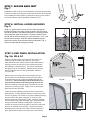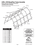
1
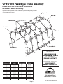
12'W x10'H Peak Style Frame Assembly
Please read and understand instructions
completely before assembly.
Layout out frame parts as shown and match up items with quantity to make
sure no parts are missing.
Top Rail
End Rib
Middle Ribs
End Rib
Side Rails
Cover Rails
Wind Brace
ATTENTION:
Wind Brace
FOR MISSING OR
REPLACEMENT PARTS
OR QUESTIONS,
PLEASE CONTACT
Assembly
Reference #
Mfg.
Part #
Assembly
Reference #
Mfg.
Part #
CUSTOMER SERVICE:
1.800.524.9970
1
2
3
4
5
6
7
8
9
10
11
10131
10121
10132
10125
10126
10127
10128
10133
2030
10134
2031
12
13
14
15
16
17
18
19
20
21
22
10135
10110
10111
10112
669
10210
10114
10115
10113
10223
800260
CANADA 1.800.559.6175
Page 2
www.shelterlogic.com
150 Callender Road
Watertown, CT 06795
05-101133-0C 09/04/07
Basic Frame Assembly
NOTE: FRAME EXTENSION KIT
12'x20'x10' is the base frame dimension. Your model may have more middle ribs than shown in the illustration on pg.2. You will
receive one extra rib for every extra 4 ft. of building length that you purchase. The basic frame assembly will remain the same. The
cover will be the correct size for the length of the building.
STEP 1: PLOTTING THE FRAME
Fig. 1
12'
Before building your shelter, you should choose a flat area on your property and plot
your shelter.
1. Stake out the area for the shelter in the desired spot. The width of the area
should be at least equal to the width of the shelter and the length should be
equal to the length (“L”) of the shelter Fig. 1.
2. To be sure the staked area is square tie a rope diagonally from corner to corner.
3. Measure from where the two ropes intersect each other to all 4 corners. This
measurement should be the same. If they are not equal the stakes need to be
adjusted until the width, length and inside measurements are correct.
Length of
Building
12'
Fig.1
10121
10125
STEP 2: ASSEMBLE END RIBS
Fig. 2
Assemble end ribs as shown in Fig. 2. Securely
fasten all of the joints with the hardware indicated.
10125
10132
10132
10223
10223
10127
2" Bolts
End Rib
10127
10128
Fig.2
10128
10131
10125
STEP 3: ASSEMBLE MIDDLE RIBS
Fig. 3
Assemble all of the middle ribs as shown in Fig. 3. Securely fasten
all of the joints with the hardware indicated.
10125
10132
10132
10223
10223
2" Bolts
Middle Rib
10126
Page 3
Fig.3
10126
11102
STEP 4: INSTALL SIDE RAILS AND
SHELTERLOCK™ STABILIZER BLOCKS
Fig. 4
11102
With help move the first end rib into the desired staked area. Place
the ShelterLock on the upright as shown in Fig. 4. From the outside
of the rib insert the bolt through the upright and then through the
ShelterLock. Place the plain end of the side rail over the bolt and
nest it into the ShelterLock. Install the nut onto the bolt and tighten.
Repeat these steps for the opposite side and all of the remaining ribs.
The side rails for the last rib will have two plain ends.
800260
10210
Fig. 2
01010
Fig. 4
STEP 5: INSTALL WIND BRACES
Fig. 5
2030
Take the wind brace and attach it between the end rib and the
first middle rib as shown in Fig. 5. Any attachments at the
cross rails should be made on the very inside of the cross rail.
2030
10135
Wind Brace
10135
Fig. 5
STEP 6: INSTALL TOP RAIL
Fig. 6
Place the first top rail over the pipe on the top end connector Fig. 6. The same cross
rail should lay on top of the first middle rib as with all of the middle ribs. Secure the
rails to the frame with the hardware indicated in Fig 6. The top rail attached to the
last rib will be installed over the pipe on the top end connector.
Install the Top Rail
Over all Middle Ribs
669
Page 4
Fig. 6
STEP 7: SECURE BASE FEET
Fig. 7
Depending on the model you have purchased, your base feet will either
fit onto the outside of the leg pole or slide into the bottom of the leg pole.
After installing the base feet line up the holes in the leg to the holes in
the feet and secure with the hardware indicated in Fig. 7.
Fig. 7
STEP 8: INSTALL AUGER ANCHORS
Fig. 8
Using a ¾” pipe or steel rod (a car tire iron works also) placed
through the eyelet of the auger; screw the anchor into the ground.
Start at the corners of the shelter and space the remaining anchors
evenly along the length of the shelter. Screw the anchor into the
ground until the eyelet is sticking out of the ground by 1-2” so it can
be anchored to the legs. Wrap the cable provided through the
eyelet of the anchor and around the frame as indicated in Fig. 8.
Secure the cable with the clamp(s) provided.
Fig. 8
STEP 9: END PANEL INSTALLATION
Fig. 9A, 9B & 9C
Hold the end panel at the top center with the white inner
surface facing the inside of the shelter (if you have a
white shelter the inner surface has the visible weld seams).
Carefully remove the top rail from the top bend and place
the webbing in between the two. The top rail should pass
through the loop of the webbing. Replace the top rail onto
the top bend and secure it with the hardware indicated
in Fig. 9A, 9B.
Remove the nut from the side rail and carefully pull the
side rail away from the ShelterLock (the rail only needs to
be pulled away enough to pass the webbing through the
connection). If this connection has the wind brace on it
remove the wind brace end before pulling the side rail.
When the webbing is through replace the side rail, and the
cross rail if necessary Fig 9C. Replace the nut and tighten.
Repeat this for the other side.
Locate where the webbing exits the pocket on each side of
the end panel. Pull the webbing carefully to remove the slack
from the end panel. Be careful not to pull the webbing through
the other side of the panel. Install the “S”-hook from the
ratchet into the leg of the shelter Fig 9D. Insert the webbing
into the spindle of the ratchet and pull tight. Wind the ratchet
enough so that the webbing overlaps itself. Repeat the
process on the other side of the panel. Position the end panel
so that it is centered on the building. Tighten the ratchets,
alternating from one side to the other, until the end panel is
tight. Repeat these steps on the other end of the building.
Page 5
Inside View
Side View
Fig. 9A
Fig. 9C
Fig. 9B
Fig. 9D
STEP 10: INSTALLING THE
COVER ON THE FRAME:
Fig. 10A, 10B, 10C & 10D
1. Lay the cover on the ground next to the
frame with the inside of the cover (the side with
the pipe pockets) facing down and the webbing
on the front and rear of the corner of the
building. Position the cover so that it is
centered on the frame, front to back. Fig. 10A
2. Fold over the side closest to the frame so
the pipe pocket is now accessible. Insert a
cover pipe at the first middle rib from the front
and the first middle rib from the rear so that it is
inserted in the pipe pocket on both ends of the
pipe but the center of the pipe is exposed. For
long buildings it may be necessary to use
additional pipes in the middle. Fig. 10B
Fig. 10A
3. Tie the rope on each of the exposed pipes
and throw the other end of the rope over the
frame. FIg. 10C
4. Move to the other side of the frame and pull
the cover over the frame with the rope. This
may require two or more people. Fig. 10D
Fig. 10B
Fig. 10C
Fig. 10D
Page 6
Outside Corner View
STEP 11: SECURE YOUR COVER:
Fig. 11A, 11B, 12 & 13
Install the “S”-hook from the ratchet assembly into the legs of the
shelter. Pull the webbing carefully to remove the slack from the cover.
Be careful not to pull the webbing through the opposite side of the
cover. Insert the webbing through the spindle of the ratchet and pull
tight. Wind the ratchet until the webbing overlaps itself.
Repeat these steps on the opposite side. Repeat this on
the back side of the shelter. When all of the corners
are secured move the cover front to back so that it is
centered.When the cover is centered tighten all of the
ratchets. Do this in an “X” pattern to be sure it is
tightened evenly. Fig. 11A & 11B. When the cover is
tight from end to end install the 45” cover rails. Insert
the cover rails into the pockets of the cover. Clamp the
rails to the ribs using the 3-way and 4-way clamps as
shown in Fig. 12 & 13.
Check that the rails are evenly spaced above the
ground on both sides. Push down on the connectors,
one at a time, to tighten the cover. Tighten the bolts to the
cover in place and tight on the frame.
Fig. 11A
CORRECT
COVER TIGHTENING TIP
Check and tighten
Ratchets and Cross
Rails monthly to
ensure the cover
is tight.
IS YOUR COVER
PULLED CORRECTLY
ON THE FRAME?
Fig. 11B
Fig. 11B
INCORRECT
Fig.13
Fig.12
11130
clamps
11130
11106
clamps
11107
690
690
middle leg
corner leg
NOTE: ShelterLogic logo should line up on the left front and right rear corners near the top rail. If it is not legible and positioned
as shown above as “incorrect”, the cover has not been put on the frame correctly.
WARNING: Serious injury to persons or property could result if cover is installed and shelter is not completed and is left
unattended. Shelter must be anchored securely until completed.
Page 7