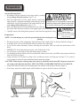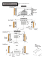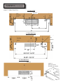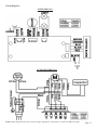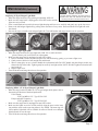
1
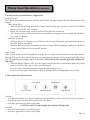
5
0
0WWa
r
n
e
r
,
Sa
n
t
aAn
aCA9
2
7
0
7
T
e
c
h
n
i
c
a
l
Su
p
p
o
r
t
:
7
1
4
6
2
2
1
5
5
0
c
a
v
a
l
i
e
r
e
h
o
o
d
s
.
c
o
m
I
nst
al
l
at
i
onManual
Important Safety Notice
Read all Instructions before Installing and operating this appliance
• The installation in this manual is intended for qualified installers, service technicians or persons with
similar qualified background. Installation and electrical wiring must be done by qualified professionals and in accordance with all applicable codes and standards, including fire-rated construction.
• DO NOT attempt to install this appliance yourself. Injury could result from installing the unit due to
lack of appropriate electrical and technical background.
• Range hood may have very sharp edges; please wear protective gloves if it is necessary to remove any
parts for installing, cleaning or servicing.
• Activating any switch ON before completing installation may cause ignition or an explosion.
• Due to the size and weight of this range hood, two people installation is recommended.
To reduce the risk of fire, electric shock, or injury to persons:
• For general ventilating use only. DO NOT use to exhaust hazardous or explosive materials and vapors.
• The combustion air flow needed for safe operation of fuel-burning equipment may be affected by this
unit’s operation. Follow the heating equipment manufacturer’s guideline and safety standards such
as those published by the National Fire Protection Association (NFPA), and the American Society of
Heating, Refrigeration and Air Conditioning Engineers (ASHRAE), and the local code authorities.
• Before servicing or cleaning unit, switch power OFF at service panel and lock service panel to prevent power from being switched ON accidentally.
• Clean grease laden surfaces frequently. To reduce the risk of fire and to disperse air properly, make
sure to vent air outside. DO NOT vent exhaust into spaces between walls, crawl spaces, ceiling, attics
or garages.
• Ducted fans MUST always be vented to the outdoors.
• Use only metal ductwork and this unit MUST be grounded.
• Sufficient air is needed for proper combustion and exhausting of gases through the duct to prevent
back drafting.
• When cutting or drilling into wall or ceiling, be careful not to damage electrical wiring or other hidden utilities.
• All electrical wiring must be properly installed, insulated and grounded.
• Old duct work should be cleaned or replaced if necessary to avoid the possibility of a grease fire.
• Check all joints on duct work to insure proper connection and all joints should be properly taped.
• Use this unit only in the manner intended by the manufacturer. If you have questions, contact the
vendor.
To reduce the risk of a stove top grease fire:
• Keep all fan, baffle, spaces, filter, grease tunnel, oil container and grease-laden surfaces clean. Grease
should not be allowed to accumulate on fan, baffle, spaces, filter, grease tunnel and oil container.
• Always turn range hood ON when cooking at high heat or when cooking flaming foods.
• Use high settings on cooking range only when necessary.
• Never leave surface units unattended at high settings. Boil overs cause smoking and greasy spillovers
that may ignite. Heat oils slowly on low or medium settings.
Page 1
Important Safety Notice
Read all Instructions before Installing and operating this appliance
• Clean ventilating fan frequently.
• Always use appropriate cookware and utensils size.
• Always use cookware appropriate for the size of the surface element.
To reduce the risk of injury to persons in the event of a stove top grease fire:
• SMOTHER FLAMES with a close-fitting lid, cookie sheet, or metal tray, then turn OFF the burner.
BECAREFUL TO PREVENT BURNS. NEVER PICK UP A FLAMING PAN—you may be burned.
KEEP FLAMMABLE OR COMBUSTIBLE MATERIAL AWAY FROM FLAMES. If the flames DO
NOT go out immediately, EVACUATE AND CALL THE FIRE DEPARTMENT or dial your local
emergency service immediately.
• DO NOT USE WATER, including wet dishcloths or towels — a violent steam explosion will result.
• Use an extinguisher ONLY if:
• You know you have a Class A, B, C extinguisher, and you already know how to operate it.
• The fire is small and contained in the area where it is started.
• The fire department is being called.
• You can fight the fire with your back to an exit.
To reduce the risk of injury to persons in the event of a gas leaks:
•
•
•
•
Extinguish any open flame.
DO NOT turn on the range hood fan or any type of ventilator.
DO NOT turn on the lights or any type of appliance.
Open all doors and windows to disperse the gas. If you still smell gas, call the gas company and fire
department, or dial your local emergency service immediately.
Your safety and the safety of others is very important. We have provided many important safety messages in this manual and on your appliance. Always read and obey all safety messages. All safety messages will tell you what the potential hazard is, tell you how to reduce the chance of injury, and tell you
what can happen if the instructions are not followed.
WARNING
This is the safety alert symbol. This symbol alerts you to potential hazards that can hurt you and others.
All safety messages will follow the safety alert symbol and the word “WARNING”.
The manufacturer and/or distributor/reseller declines all responsibility in the event of failure to observe the instructions given here for installation, maintenance and suitable use of the product.
The manufacturer and/or distributor/reseller further declines all responsibility for injury due to negligence and the warranty of the unit automatically expires due to improper maintenance.
The manufacturer and/or distributor/reseller will not be held responsible for any damages to personal property or real estate or any bodily injuries whether caused directly or indirectly by the range
hood.
Page 2
Table of Contents
INSTALLATION
Tools needed....................................................3
Parts supplied...................................................4
Venting requirements.......................................5
Mount heights & clearance...........................5-6
Calculating vent system length.......................6
Venting methods & charcoal filters.................7
Ductless conversion & electrical requirements.8
Preparation......................................................9
Installation................................................10-12
Range hood operations.............................13-14
USE AND CARE
Troubleshooting...........................................15
Use and care information...............................16
Specifications..............................................16
Measurements & Diagrams......................17-21
MAINTENANCE
Cleaning.................................................22
Replacing the filter & light bulb...............22-23
WARRANTY
Coverage & exceptions..................................24
Disclaimer & Contact Us...............................25
Tools needed:
Marker or
pencil
Measuring
tape
Utility knife
Level
Powered
screwdriver
or drill
Flat-blade
and Phillips
screwdrivers
Page 3
Parts Supplied:
UC200 Series Under Cabinet Range Hood (vary with model)
Aluminum Filters
(Pre-Installed)
for 1900 & 2000 Class
for 4100 Class
for 1800 Class
Rectangular Exhaust/Vent Adapter
Round Exhaust /VentAdapter
(For vertical or horizontal venting)
(For vertical venting)
Qty: 4 PCS
(For sheet rock only)
Qty: 4 PCS
Charcoal filter
(Optional re-circulating kit
available only on UC2002000 Class)
Page 4
Venting Requirements
•
•
•
•
•
•
•
Height & Clearance
Vent system must terminate to the outside
(roof or side wall).
DO NOT terminate the vent system in an attic or other enclosed area.
DO NOT use 4” (10.2 cm) laundry-type wall
caps.
Use metal/aluminum vent only. Rigid metal/
aluminum vent is recommended.
DO NOT use plastic vent.
Always keep the duct clean to ensure proper
airflow.
Calculate the following figures before installation:
1. Distance from the floor to the ceiling.
2. Distance between the floor to the countertop/stove.
3. Distance between the countertop/stove
to the range hood (recommend* 27” to
30”).
4. Height of hood and duct cover/cabinet.
Cabinet
Height
Range
Hood
Height
Under Cabinet
Range hood
For the most efficient & quiet operation:
•
•
•
•
•
•
•
•
•
•
A distance of 27” to 30” is recommended*
between stove top and the bottom of range
hood.
It is recommended that the range hood be
vented vertically through the roof through 6”
(15.3 cm) or bigger round metal/aluminum
vent work.
The size of the vent should be uniform.
Use no more than three 90° elbows.
Make sure there is a minimum of 24” (61
cm) of straight vent between the elbows if
more than one elbow is used.
DO NOT install two elbows together.
The length of vent system and number of
elbows should be kept to a minimum to provide efficient performance.
The vent system must have a damper. If
roof or wall cap has a damper, DO NOT
use damper (if supplied) on top of the range
hood.
Use silver tape or duct tape to seal all joints
in the vent system.
Use caulking to seal exterior wall or roof
opening around the cap.
* Due to different ceiling height configurations, recommended height may not be applicable.
Cabinet
Min: 27”
Max: 30”
Ceiling
Height
Countertop/Stove
36”
Counter
Top
Page 5
IMPORTANT:
• A minimum of 6” round (standard for this range hood) or 3-1/4 x 10” rectangular duct (purchased separately) must be used to maintain maximum airflow efficiency.
• Always use rigid type metal/aluminum ducts if available to maximize airflow when connecting to provided
duct.
• Please use Duct Run Calculation below to compute total available duct run when using elbows, transitions
and caps.
• ALWAYS, when possible, reduce the number or transitions and turns. If long duct run is required, increase
duct size from 6” to 7” or 8”. If a reducer is used, install a long reducer instead of a pancake reducer. Reducing duct size will restrict airflow and decrease airflow, thus reduce duct size as far away from opening as
possible.
• If turns or transitions are required: Install as far away from opening and as far apart, between 2, as possible.
• Minimum mount height between stove top to hood bottom should be no less than 27-inch*.
• Maximum mount height between stove top to hood bottom should be no higher than 30-inch*.
• It is important to install the hood at the proper mounting height. Hoods mounted too low could result in heat
damage and fire hazard; while hoods mounted too high will be hard to reach and will loose its performance
and efficiency.
• If available, also refer to stove top manufacturer’s height clearance requirements and recommended hood
mounting height above range.
* Due to different ceiling height configurations, recommended height may not be applicable.
Minimum Duct Size:
• Round - 6” minimum
• Rectangular - 3-1/4 x 10” minimum (requires a provided 3-1/4x10” adaptor)
Calculating Vent System Length
To calculate the length of the system you need, deduct the equivalent feet for each vent piece used in the system
from the recommended maximum duct run.
Duct Run Calculation:
Recommended maximum run
6” or 3-1/4 x 10” duct
50 ft
Vent piece deduction
Each 90º elbow used
9 ft
Each 45º elbow used
5 ft
Each 6” to 3/14 x 10” transition used
7 ft
Side wall cap with damper
0 ft
Roof cap
0 ft
Duct Run Calcuation example:
One roof cap, two 90º elbow, and one 45º elbow used:
0ft + 9ft + 9ft + 5ft = 23ft used.
Deduct 23ft from 50ft, 27ft maximum available for
straight duct run.
Page 6
Venting Methods
IMPORTANT:
• NEVER exhaust air or terminate duct work into spaces between walls, crawl spaces, ceiling, attics or
garages. All exhaust must be ducted to the outside.
• Use metal/aluminum duct work only.
• Fasten all connections with sheet metal screws and tape all joints with certified Silver Tape or Duct Tape.
• Use caulking to seal exterior wall or roof opening around the cap.
Venting Methods:
• Vent work can terminate either through the roof or wall. To vent through a wall, a 90° elbow may be needed.
• This range hood is factory set for vertical venting using round or rectangular vent adapter but can be converted to horizontal venting by swapping the round vent adapter on top with rectangular vent adapter behind
the range hood as shown below:
Option 1:
Recirculate venting
(available with 2000 Class only)
Option 2:
Horizontal wall venting
Option 3:
Vertical roof venting
Roof cap
Side wall cap
Type 1:
3-1/4 x 10-inch rectangular vent
adapter behind the range hood.
Type 2:
3-1/4 x 10-inch rectangular vent
adapter on top of the range hood.
Type 3:
6-inch round vent adapter on top
of the range hood.
Charcoal Filter Installation
NOTE: The charcoal filters are preinstalled if you purchased the range hood with re-circulating kit from us.
1. Remove aluminum filters on hood.
2. Position the charcoal filter onto the motor and turn until it locks. Re-install aluminum filters.
3. Charcoal filters must be replaced after 120 hours of use (or approximately every 2 to 3 months based on the
average of 1 to 2 hours of daily cooking time). Available at your local resellers.
Page 7
Ductless Conversion
• Ductless conversion is intended for applications where an exhaust duct work is not possible to be installed.
When converted, the hood functions as a purifying hood rather than an exhaust hood. Fumes and exhaust
from cooking is drawn and filtered by a set of charcoal filters. The air is then purified and re-circulated back
within the home.
• We recommend to ALWAYS exhaust air outside of the home by employing existing or installing new duct
work, if possible. Only when the exhaust option is not possible should you recourse to converting the hood
into a purifying unit.
• When converted to be a “purifying” unit, a set of charcoal filters and an air-diverter are required in addition to
its standard aluminum filter set. Available at your local resellers. The standard aluminum filters are intended
to capture residue from cooking, the optional charcoal filters help to purify fumes exhausted from cooking,
and the optional air-diverter redirects filtered clean air back to the house.
Electrical Requirements
IMPORTANT: Observe all governing codes and ordinances.
(Please consult with a qualified electrician for 220-Volt 50 Hz voltage)
It is the customer’s responsibility:
• To contact a qualified electrical installer.
• To assure that the electrical installation is adequate and in conformance with National Electrical Code, ANSI/
NFPA 70 — latest edition*, or CSA Standards C22. 1-94, Canadian Electrical Code, Part 1 and C22. 2 No.
0-M91 - latest edition** and all local codes and ordinances.
If codes permit and a separate ground wire is used, it is recommended that a qualified electrician determine that
the ground path is adequate.
A 120-Volt, 60 Hz, AC-only, fused electrical supply is required on a separate 15-amp circuit, fused on both sides
of the line.
DO NOT ground to a gas pipe.
Check with a qualified electrician if you are not sure that the range hood is properly grounded.
DO NOT have a fuse in the neutral or ground circuit.
IMPORTANT: Save this Installation Guide for electrical inspector’s use.
The range hood must be connected with copper wire/plug only.
The range hood should be connected directly to the fused disconnect (or circuit breaker) box through flexible
armored or non-metallic sheathed copper cable. A U.L. - or C.S.A. - listed strain relief must be provided at each
end of the power supply cable.
Wire sizes (copper wire only) and connections must conform with the rating of the appliance as specified on
the model/serial rating label. Wire sizes must conform to the requirements of the National Electrical Code
ANSI/NFPA 70 — latest edition*, or CSA Standards C22. 1-94, Canadian Electrical Code Part 1 and C22.
2 No. 0-M91 - latest edition** and all local codes and ordinances. A U.L. - or C.S.A. - listed conduit connector must be provided at each end of the power supply cable (at the range hood and at the junction box).
Copies of the standards listed may be obtained from:
* National Fire Protection Association
Batterymarch Park
Quincy, Massachusetts 02269
** CSA International
8501 East Pleasant Valley Road
Cleveland, Ohio 44131-5575
Page 8
Preparation
WARNING
Advanced Preparations:
• Be familiar with the controls of the range hood by reading
through Range Hood Operations, Page 13-14.
• Place the range hood on a flat, stable surface. Connect the
Excessive Weight
range hood to a designated standard outlet and turn on the Require three or more person to move and
range hood. Verify all operations of the range hood by refer- install this range hood. Spinal or other bodiring to Range Hood Operations, Page 13-14.
ly injuries could occur if it is not followed.
• Place all supplied parts and required hardware on a flat, stable surface and verify the existence of all supplied parts listed on Page 4.
• Carefully remove the white plastic protective coat from the range hood, if any.
WARNING
Severe Injury
Preparations:
NOTE: To avoid damage to your hood, prevent debris from entering the vent
opening.
Rotating fan can cause severe
injury. Stay clear of fan when
motor is running.
• Decide the location of the venting pipe from the hood to the outside. Refer to Venting Methods on Page 7.
• A straight, short vent run will allow the hood to perform more efficiently.
• Try to avoid as many transitions, elbows, and long run as possible. This may reduce the performance of the
hood.
• IMPORTANT: Peel white plastic protective coat off the hood, if any.
• Use silver tape or duct tape to seal joints between pipe sections.
• For installing under the cabinet with recessed bottom, attach 4-inch wide wood filler strips (not provided) on
each side. Refer to Figure 1.
• Using references in Installation on Page 10-12 and Measurements and Diagrams on Page 17-21, create access opening for electrical wires and hood exhaust under the cabinet.
CAUTION: If moving the cooking range is necessary to install the hood, turn OFF the power on an electric range at the main electrical box. SHUT OFF THE GAS BEFORE MOVING A GAS RANGE.
• Puncture the knockout holes (for mounting under the cabinet) on the hood as shown in Figure 2.
• If necessary, attach two rubber stands with 3M adhesive tapes to the back corners of the hood.
Figure 1
Figure 2
Page 9
Installation
Installations (refer to Page 4 for parts):
Measure the distance between stove top and the bottom of
range hood. A distance of 27” to 30” is recommended*.
*Due to different ceiling height configurations, recommended height may not be applicable.
1. You have two ways (A: Vertical Venting, or B: Horizontal Venting) to mount this range hood:
1.
Determine venting method as shown on Page 7 and proceed if you would like to vent vertically.
2.
Using references in Height & Clearance on Page 5-6, Measurements and Diagrams on Page 17-21,
Figure 3 and Figure 4 on next page, determine and clearly mark a centerline on the bottom of the cabinet.
3.
Draw electrical wires through cabinet access opening on top of the range hood, center the hood beneath
the cabinet and flush with the front of the cabinet.
4.
From inside of the hood, place hood mounting screws into the exact center of each knockout hole and
secure to cabinet bottom. Finish tightening all screws until secure. Be careful when using electrical
screwdriver, damage to the range hood may occur. Skip Part B below and proceed to Step 2.
CAUTION: Make certain the range hood is secure before releasing!
1.
2.
3.
4.
5.
Determine venting method as shown on Page 7 and proceed if you would like to vent horizontally.
Using references in Height & Clearance on Page 5-6, Measurements and Diagrams on Page 17-21,
Figure 5 and Figure 6 on next page, determine and clearly mark a centerline on the wall.
Punchure the knockout wire access hole and rear duct access hole on the back of the hood, draw electrical wires through the wire access hole and attach rectangular vent adapter.
Draw electrical wires through the access opening on the wall behind the range hood (Figure 6), center
the hood beneath the cabinet and flush with the front of the cabinet.
From inside of the hood, place hood mounting screws into the exact center of each knockout hole and
secure to the wall. Finish tightening all screws until secure. Be careful when using electrical screwdriver, damage to the range hood may occur.
CAUTION: Make certain the range hood is secure before releasing!
2. For safety purpose, pre-drilled mounting holes are provided through the back of the hood. For a more secure
installation, use as many mounting holes as needed to secure from the inside of hood.
1. Use 6” round steel pipe (follow building codes in your area) to connect the exhaust on the hood to the ductwork above. Use silver tape or duct tape to make all joints secure and air tight. Refer to Figure 6.
SAFETY WARNING: Risk of electrical shock. this range hood must be properly grounded. Make sure this
is done by qualified electrician in accordance with all applicable national and local electrical codes. Before
connecting wires, switch power off at service panel and lock service panel to prevent power from being
switched on accidentally.
1. Connect the range hood to a designated standard outlet or cut off the plug and connect three wires (black,
white and green) to house wires and cap with wire connectors. Connect according to colors (i.e. black to
black, white to white, and green to green).
2. Store excess wires in the wiring box.
3. Turn Power ON using control panel (refer to Range Hood Operations on Page 13-14). Check all lights and
fan operations.
4. Make sure to leave this Installation Guide for the homeowner.
Page 10
Installation (Continued)
Figure 3: Cabinet Bottom View
UC200-4130W
Wood Filler Strips
(Not included)
Hood
Mounting
Screws
Electrical
Access
Opening
Wall
Centerline
UC200-2000 Class
Wood Filler Strips
(Not included)
Hood
Mounting
Screws
Electrical
Access
Opening
Wall
Centerline
UC200-1900 Class
Wood Filler Strips
(Not included)
Electrical
Access
Opening
Wood Filler Strips
(Not included)
Wall
Centerline
UC200-1800 Class
Electrical
Access
Opening
Centerline
Hood
Mounting
Screws
Figure 4:
Electrical wires
through top opening
Wall
Hood
Mounting
Screws
Page 11
Installation (Continued)
Figure 5: Cabinet Front View
UC200-4130W
Centerline
Hood
Mounting
Screws
UC200-1900 Class
Centerline
Hood
Mounting
Screws
UC200-1800 Class
Centerline
Electrical
Wire
Opening
Electrical
Wire
Opening
Figure 6:
Electrical wires
through rear opening
Page 12
Range Hood Operations
Control Panel Layout and Buttons Configurations:
1. Electronic Control
Filter Clean
Reminder
Light Control
Quiet
Speed
Low
Speed
High
Speed
Power Control
(On/Off)
This range hood is equipped with five electronic controls, a powerful centrifugal squirrel cage motor with two
aluminum filters, two bright 20W~12V or 40W~120/240V halogen lights and a filter clean reminder.
The five electronic buttons control the intensity of the Lights, Speeds (Quiet, Low and High) and Power (On/Off).
The Power Control (On/Off) offers startup, 3-minute delay or immediate power-off. The Light Control operates
independently from the Power Control (On/Off) and is not affected by the delay shutoff.
The aluminum filters are designed to deliver approximately 3 months of grease filtration between each cleaning.
The Filter Clean Reminder is set to turn ON after 100-hours of fan operation have elapsed since the installation
of cleaned or new filters. The timer for this reminder light will reset each time the filter is removed and the trigger
is released.
Filter Clean Reminder
Timer Reset Trigger
Turning Fan ON:
Always turn fans ON couple minutes before cooking to establish air flow and allow fans to run for a few minutes
after cooking for cleaner air in the kitchen. The Power Control (On/Off) button must be pressed before a Speed
Control button can be activated.
NOTE: The light setting will not be affected by the Power Control (On/Off) button.
• With the range hood is OFF, press the Power Control (On/Off) button once. The LED on the Power Control
button will be illuminated.
• While the Power Control LED is illuminated, press one of the three speed control button (Quiet, Low and
High) to activate the desired speed (the LED on the speed control button will turn on).
• To change the fan speed, press another speed control button. The LED on the speed control button will become illuminated accordingly.
Page 13
Range Hood Operations (Continued)
Control Panel Layout and Buttons Configurations:
Turning Fan OFF:
The 3-minute power-off delay function will only turn OFF fans. The light settings will not be affected by the delay
function.
Three-Minute Delay
• While the fans are operating, press Power Control (On/Off) button once, the Power Control LED will flash
and fans will turn OFF after 3-minutes.
• During this 3-minutes delay, changing speeds will not affect the countdown.
• The 3-minute power-off delay function can be cancelled by pressing press Power Control (On/Off) button
once while it is flashing.
Immediate Power-off
• While the fans are in 3-minute power-off delay mode, press the illuminated speed control button once to
turn OFF the fans immediately.
• When the fans are operating in normal mode (Power Control LED not flashing), rapidly press the Power
Control (On/Off) button twice to turn OFF the fans.
Light Control:
Light Control button operates independently from the Power Control (On/Off) and power-off delay function.
Pressing the Power Control (On/Off) button or activating the delay function will not turn halogen lights ON or
OFF. The lights have three settings: High, Low and OFF. CAUTION: DO NOT touch the lights until switched OFF
and cooled.
• While the halogen lights are OFF, press the Light Control button once to turn halogen lights ON at High
intensity. LED on Light Control will become illuminated.
• Press the Light Control button again to change the light intensity to Low.
• Each touch of the Light Control button will cycle the light intensity through High, Low, and OFF.
2. Three Speed Mechanical Control
Low Speed
Power Switch
High Speed
Medium Speed
Light Switch
Turn On:
• Press the speed control (Low Speed, Medium Speed, High Speed) switch to select the desired level of power.
Once button is pressed, the previous speed mode will cancel.
• Press the Light Switch to power on the lights.
CAUTION: DO NOT touch the lights until switched OFF and cooled.
Turn Off:
• Press the Power Switch to turn off the power.
• Press the Light Switch to power off the lights
Page 14
Troubleshooting
1. If the range hood or halogen light does not operate
after installation:
• Check if the range hood has been plugged in, make
sure that all power has been turned back ON, fused
not blown and all electrical wiring are properly connected.
• Swap out light assembly to working ones to determine whether it is caused by defective bulbs. See
Replacing the light bulbs on Page 22.
2. The range hood vibrates when the blower is on:
• The range hood might not have been secured properly on to the ceiling or wall.
3. The blower or fan seems weak:
• Check that the duct sized used is at least 6” or 3-1/4
x 10”. Range hood WILL NOT function efficiently
with insufficient duct size. For example: 7” duct
over 6” hole and loosely secured.
• Check if duct is clogged or if damper unit (half-circular flapper) is not installed correctly or opening
properly. A tight mesh on a side wall cap unit might
also cause restriction to the air flow.
4. The lights work but the blower is not spinning at all, • The blower might be jammed or scraping the botis stuck or is rattling.
tom due to shipping damage. Please contact us immediately.
5. The hood is not venting out properly:
• Make sure the distance between the stove top and
the bottom of the hood is within* 27” and 30” in
distance. *Due to different ceiling height configurations, recommended height may not be applicable.
• Reduce the number of elbows and length of duct
work. Check if all joints are properly connected,
sealed, and taped.
• Make sure the power is on high speed for heavy
cooking.
NOTE: For all other inquiries, please contact us. Our contact information can be found on the back cover.
Page 15
Use and Care Information
Operations:
• Read and understand all instructions and warnings in this manual before operating the appliance. Save these
instructions for future reference.
• Always leave safety grills and filters in place. Without these components, operating blowers could catch on to
hair, fingers and loose clothing.
• NEVER dispose cigarette ashes, ignitable substances, or any foreign objects into blowers.
• NEVER leave cooking unattended. When frying, oil in the pan can easily overheat and catch fire. The risk of
self combustion is higher when the oil has been used several times.
• NEVER cook on “open” flames under the range hood. Check deep-fryers during use: Superheated oil may be
flammable.
Cleaning:
• The saturation of greasy residue in the blower and filters may cause increased inflammability. Keep unit clean
and free of grease and residue build-up at all times to prevent possible fires.
• Filters must be cleaned periodically and free from accumulation of cooking residue (see cleaning instructions
on Page 22). Old and worn filters must be replaced immediately.
• DO NOT operate blowers when filters are removed. Never disassemble parts to clean without proper instructions. Disassembly is recommended to be performed by qualified personnel only. Read and understand all
instructions and warnings in this manual before proceeding.
Specifications
Body Design
Power Rating
General Input Power
Motor Input Power
Ampere
Levels Of Speed Control
Airflow1 (Max)
Noise Level2 (Q/L/M/H)
Number Of Motors
Motor Type
Fan Type
Control Type
Filtration Type
Illumination
Venting Size
Interference Protection
Specifications3:
Stainless Steel or Seamless Steel, Powder Coating
220V/50Hz or 120V/60Hz (USA & Canada standard)
4100 Class: 208W, 19/2000 Class: 168W, 1800 Class: 198W
128 W
1.5 A
3 Levels
1900/2000/4100 Class: 400CFM, 1800 Class: 280CFM
1.0 Sone (40 dB) / 2.8 Sone (55 dB) / 4.0 Sone (60 dB)
Single Motor
Single Chamber Ultra Quiet
Centrifugal Squirrel Cage
Mechanical or Electronic Button Control Panel
Aluminum Filter
20W/12V, 35W/12V or 40W/120V Maximum
6 inches Round (Top); 3-1/4 x 10 inches Rectangular (Top & Rear)
Radio Frequency Interference Protected
1. In House Test Static Pressure “0”.
2. One sone is roughly equivalent to the sound of a refrigerator (1kHz) at 40 decibels.
3. Subject to change without notice, please contact your local reseller for details.
Page 16
Measurements and Diagrams
• All measurements in parenthesis are in millimeter.
• All inch measurements are converted from millimeters, thus inch measurements are estimated.
UC200-4100 Class:
Front View
Rear View:
Top View:
Page 17
• All measurements in parenthesis are in millimeter.
• All inch measurements are converted from millimeters, thus inch measurements are estimated.
UC200-2000 Class:
Front View
Rear View:
Top View:
Page 18
• All measurements in parenthesis are in millimeter.
• All inch measurements are converted from millimeters, thus inch measurements are estimated.
UC200-1900 Class:
Front View
Rear View:
Top View:
Page 19
• All measurements in parenthesis are in millimeter.
• All inch measurements are converted from millimeters, thus inch measurements are estimated.
UC200-1800 Class:
Front View
Rear View:
Top View:
Page 20
Circuit Diagram:
UC200-4100 Class
GREEN
UC200-18/19/2000 Class
NOTE: Wiring Diagram shown above with GU10 light configuration. A transformer is required for MR16/J4 Lights.
Page 21
Maintenance
SAFETY WARNING: Never put your hand into area housing the
fan while the fan is operating!
For optimal operation, clean range hood & all filter/oil container regularly. Regular care will help preserve the range hood’s performance &
appearance.
WARNING
Hazard of Burns!
Light bulb become extremely hot when turned on.
DO NOT touch bulb until switched off and cooled.
Touching hot bulbs could cause serious burns.
Cleaning Exterior Surfaces:
• Clean periodically with hot soapy water and clean cotton cloth. Do not use corrosive or abrasive detergent (e.g. Comet
Power Scruv®, EZ-Off® oven cleaner), or steel wool/scoring pads, which will scratch and damage the stainless steel
surface. For heavier soil use liquid degrease such as “Forumla 409®” or “Fantastic®” brand cleaner.
• If hood looks splotchy (stainless steel hood), use a stainless steel cleaner to clean the surface of the hood. Avoid getting
cleaning solution onto or into the control panel. Follow directions of the stainless steel cleaner. CAUTION: Do not
leave on too long as this may cause damage to hood finish. Use soft towel to wipe off the cleaning solution, gently
rub off any stubborn spots. Use dry soft towel to dry the hood.
• After cleaning, you may use non abrasive stainless steel polish such as 3M® or ZEP®, to polish and buff out the stainless
luster and grain. Always scrub lightly, with clean cotton cloth, and with the grain.
• DO NOT allow deposits to accumulate or remain on the hood.
• DO NOT use ordinary steel wool or steel brushes. Small bits of steel may adhere to the surface and cause rusting.
• DO NOT allow salt solutions, disinfectants, bleaches, or cleaning compounds to remain in contact with stainless steel
for extended periods. Many of these compounds contain chemicals, which may be harmful. Rinse with water after exposure and wipe dry with a clean cloth.
Cleaning Aluminum Grease Filter / Stainless Steel Filterless Grill:
• The aluminum filters fitted by the factory are intended to filter out residue and grease from cooking. It need not be replaced on a regular basis but are required to be kept clean. Filters should be cleaned after every 30 hours of use.
• Remove and clean by hand or dishwasher. Spray “Formula 409®” or equivalent degreasing detergent and leave to soak
if heavily soiled. Dry filters and re-install before using hood.
IMPORTANT: Drain oil from oil containers before oil and residue overflow!
Replacing Filters:
• Should filters wear out due to age and prolonged use, replace with following part number: SV168/198-ACS-AF/SF
• Note: Also replace damaged filter that has punctured or broken mesh, bent or broken frame.
Replacing J4 Type Halogen Light Fixture:
• When the range hood uses J4 type halogen light fixture: 20W 12V (Product ID: SV-ACS-HAL20W).
• Make sure the range hood is unplugged or turn OFF breaker and the lights are cool to touch.
• Place a flat-head screwdriver between light housing and hood body, gently pry up the light housing and search for the
metal clip.
• Apply force to the metal clip and pull out the light fixture. Disconnect the power cable and discard the old light fixture.
• Reverse the steps to install a new halogen light fixture. Turn ON breaker and range hood to test for operation.
Light Housing
Flat-head Screwdriver
Power Plug
Hood
Body
Metal Clip
Page 22
WARNING
Maintenance (Continued)
Hazard of Burns!
Replacing J4 Type Halogen Light Bulb:
• When the range hood uses J4 type halogen light bulb: 20W 12V.
• Make sure the range hood is unplugged or turn OFF breaker and the
lights are cool to touch.
• Place a small flat-head screwdriver between light housing and lens cover, carefully and gently pry up the lens cover.
• Remove the old halogen light bulb by pulling in the direction of wavy arrow. Do not touch the new light bulb with
bare hands.
• Reverse the steps to install a new halogen light bulb. Turn ON breaker and range hood to test for operation.
Light bulb become extremely hot when turned on.
DO NOT touch bulb until switched off and cooled.
Touching hot bulbs could cause serious burns.
Halogen Bulb
Light Housing
Lens Cover
Lens Cover
Lens Cover
Flat-head
Screwdriver
Replacing E12 Type light bulb:
• When the range hood usesE12 type light bulb: 20W 12V or 40W 120/220V.
(please contact your local reseller for replacement)
• Make sure the range hood is unplugged or turn OFF breaker.
1. Place a flat-head screwdriver between light cover and hood casing, gently pry to remove light cover.
2. Gently unscrew defective bulb straight out and discard.
3. Wear a cotton glove or use a cloth to handle the replacement bulb (DO NOT handle with bare fingers as this may
shorten the life of the bulb). Tighten gently but securely into light socket. NOTE: DO NOT tighten too hard as bulb
may break off.
4. Replace light cover.
• Turn ON breaker and range hood to test for operation.
Light
Cover
Light
Cover
Hood
Casing
Flat-head Screwdriver
Light
Bulb
Replacing MR16 / GU10 Type Halogen Light Bulb:
• When the range hood uses MR16 or GU10 type halogen bulb (please refer to
the actual specification of the hood purchased):
USA/Canada:
35W Type MR16 12V / Type GU10 120V
Europe and other Countries:
35W Type MR16 12V / Type GU10 220V
• Make sure the range hood is unplugged or turn OFF breaker.
• Make sure the lights are cool to touch, carefully align the arrow on the inner
ring with the arrow on the outer ring where it says OPEN. The inner ring will
loosen and the light bulb will be available for removal. Install a new halogen
light bulb and reverse the steps.
• Turn ON breaker and range hood to test for operation.
Align arrows on both rings
Page 23
Warranty
TO OBTAIN SERVICE UNDER WARRANTY:
You must present proof of original purchase date.
Please provide an original dated proof of purchase (sales receipt / invoice) in order to obtain service under warranty.
One Year Parts Warranty:
For one year from the date of original purchase, your local reseller will provide free of charge, non-consumable replacement parts or components that failed due to manufacturing defects. Subject to the conditions and limitations set forth
below, your local reseller will, at its option, either repair or replace any part of its products that prove defective by reason
of improper workmanship or materials. Repaired parts or replacement products will be provided by your local reseller
on an exchange basis, and will be either new or refurbished to be functionally equivalent to new. The consumer is responsible for all shipping costs. Consumable parts not covered by this warranty include but not limited to: Light bulbs,
metal, aluminum and charcoal filters.
Who is Covered:
This warranty is extended to the original purchaser for products purchased for ordinary home use.
This Warranty Will Be Voided When:
Product damaged through negligence, improper installation, accident, abuse, misuse, natural disaster, insufficient or
excessive electrical supply, abnormal mechanical or environmental conditions, or any unauthorized disassembly, repair,
modification, or failure to follow installation instructions. When product is used commercially or other than its intended
purpose. Damaged because of improper connection with equipment of other manufacturers. Repaired or modified by
anyone other than your local reseller’s authorized agents. This limited warranty also does not apply to any product on
which the original identification information has been altered, obliterated or removed, has not been handled or packaged
correctly or has been sold as second-hand.
What is Not Covered:
Consumable parts such as light bulbs, metal and charcoal filters. The natural wear of finish, and wear due to improper
maintenance, use of corrosive and abrasive cleaning products, pads, and oven cleaner products. Chips, dents or cracks
due to abuse, misuse, freight damage, or improper installation. Damage of product caused by accident, fire, floods or
act of God. The manufacturer and/or distributor/reseller is not liable for, and does not cover under warranty, any loss of
properties or any costs associated with removing, servicing, installing, or determining the source of problems with this
product.
This warranty is valid in the country of the original purchase at retail. It is non-transferable and applies only to the original
purchaser and does not extend to subsequent owners of this product. Any applicable implied warranties, including the warranty of merchantability, are limited in duration to a period of express warranty as provided herein beginning with the date
of original purchase at retail and, no warranties, whether express or implied, shall apply to this product thereafter.
To obtain warranty service, you may contact your local reseller from which you purchased this product. Please confirm the
terms of your local reseller’s policies prior to contacting. Typically, you must include product identification information,
including model number and serial number with a detailed description of the problem you are experiencing. You must also
include proof of the date of original retail purchase as evidence that the product is within the applicable warranty period.
The information in this document is subject to change without notice, please contact your local reseller for updated details.
Page 24
Disclaimer
Carefully inspect all items for damages before accepting delivery. note any damages on the freight bill or
express receipt. request name and signature of the carrier’s agent and keep copy to support your claim. Upon
acceptance of items, owner assumes responsibility for its safe arrival. Report damages to the carrier and file
a claim immediately. Failure to do so may result in the denial of your claim. The carrier will furnish you with
necessary forms for filing a claim.
Damages caused during transit are not covered under our warranty. Please contact us to file an insurance claim.
Please inspect contents of package(s) carefully upon receiving! We must be notified of any damages and/or
missing parts within five (5) days upon your receipt of package(s). Claims will not be accepted after five (5)
days. NOTE: Items were thoroughly tested and carefully packed in our factory before shipping.
Products must be returned in good working condition with ALL original parts and documentation packed in
ALL original cartons, fillers and shipping cartons. A restocking fee of 15% will be charged for all approved
return(s). Exchanges or returns may not be accepted if any packaging is missing.
Make sure to inspect the hood for damages and defects before installation. Appearance flaws of the hood found
after installation and not affecting hood performance is not covered under our warranty for returns or exchanges. Service visits not covered under warranty will carry a service charge.
Before Installation: Return for exchange or refund (please see above for acceptable returns).
After Installation: NO exchange or refund.
Contact Us
If you need any assistance, please contact your local reseller. Please have your order number and model of the
range hood ready. This information will help them better respond to your request.
If you need replacement parts, we recommend that you only use genuine parts. Our accessories and parts are
engineered and designed specifically for this series of range hood, each is rigorously tested assuring the utmost
in durability and reliability, providing a factory match, factory-installed appearance and functionality tailored to
each individual range hood model.
The information in this document is subject to change without notice, please contact your local reseller for updated details.
Page 25
5
0
0WWa
r
n
e
r
,
S
a
n
t
aA
n
aCA9
2
7
0
7
T
e
c
h
n
i
c
a
l
S
u
p
p
o
r
t
:
7
1
4
6
2
2
1
5
5
0
c
a
v
a
l
i
e
r
e
h
o
o
d
s
.
c
o
m