1
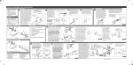
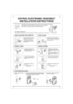
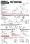
TQ2
TQ2
INSTRUCTIONS FOR INSTALLATION OF TUBULAR LEVERSETS
Latch Backset Adjustment
Backset is a distance from the door edge to the centre of the hole on door face.
Some locks are supplied with adjustable latch which can fit 2-3/8"(60mm) or 2-3/4"(70mm) backset.
Just follow the steps shown below to change backset.
A.
B.
C.
a. This latch is set for
2-3/8"(60mm)backset.
b. Keep spindle cam in correct
position as illustrated.
Pull spindle cam all the way
to right.
c. Your latch is now set for 2-3/4"(70mm) backset.
To reset 2-3/8"(60mm) backset, just push spindle
cam back to left side.
Please make sure that the cams are staying with
square shape.
Latch Face Plate
Some locks are supplied with 4-way latch which can fit mortise in or drive in.
B.
A.
C.
23 8/"
23 8/"
23 4/"
23 4/"
a. This latch is for mortise in.
b. Rotate latch face clockwise 20°
and pull out latch face.
c. This latch is for drive in.
1. Mark Door with Template
2. Drill Holes
a. Start 36"(914mm) from floor, fold and apply template
from floor, mark centre of door edge.
a. Drill 2-1/8"(54mm) hole on door face, from both sides to
avoid wood splitting.
b. Select 2-3/8"(60mm) or 2-3/4"(70mm) backset as
desired and mark centre of hole on door face.
b. Drill 1"(25.4mm) hole for latch.
(refer step 3c for drive-in latch)
3. Install Latch
A.
a. Insert latch in hole, mark outline of faceplate and chisel 5/32"(4mm) deep.
b. Insert latch and tighten screws.
c. For drive in latch, drill 31/32"(24.6mm) hole and press latch until it is
flush with door edge.
B.
TQ2
C.
TQ2
TQ2
TQ2
4. Reversible Levers
a. Please check the levers are unlocked(Entrance sets only).
Depressing lever catch with hand tool to release outside lever and pulling lever off.
Taking apart off the and cylinder from outside lever.
b. Reversing the levers from outside to inside/inside to out side, putting the cylinder
on the outside lever (Entrance sets only).
Please do the same procedures for inside lever.
c. Pushing handles in until catch clicks. Make sure levers are retained by lever.
7. Install Strike
5. Install Outside Lever
Handle can be only
installed when the timing
of "emergency release"
is set in the position
shown below.
Insert spindle through latch.
Press flush against door.
LEFT
RIGHT
HAND DOOR HAND DOOR
A.
a. Close door to make horizontal
centre line of strike.
B.
b. Measure one half of door thickness
from door stop and mark vertical
centre line of strike.
Drill 1"(25.4mm) hole 1/2"(13mm)
deep at intersection of horizontal
and vertical line of strike.
Match screw holes on strike with
centre lines on jamb.
Mark outline and chisel 1/16"
(1.6mm)deep for strike.
6. Install Inside Lever
C.
c. Install strike and tighten screws.
Install inside lever and
tighten screws until lock is firm.
FOR BACKSET 70mm (2-3/4")
TEMPLATE
54mm (2-1/8")
FOR BACKSET 60mm (2-3/8")
Fold on dotted line and fit on door edge
Fold on dotted line and fit on door edge
45 40
35
1-3/4" 1-9/16" 1-3/8"
5.5mm (7/32") x 2
hole for metal
door only
2-1/4" (57mm)
Make 1"(25.4mm)hole at center of door edge.
Rev. 13/10/2011