1
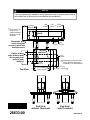
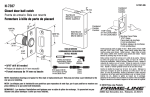
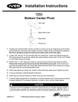
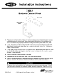
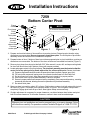
Installation Instructions
7259
Bottom Center Pivot
Clamp
screws
Pivot clamp
Finish
screws
Finish plate
Mounting
screws
Concrete
channel base
Concrete
anchor pins
!
Door
leaf
NOTE
2” minimum door thickness.
Pivot
pin
Base
plate
Figure 1
Figure 2
Figure 3
1. Prepare and mortise bottom of door and floor to receive pivot set. Determine pivot location using
dimensions on reverse side. Be sure to properly locate base plate. The finish plate of pivot base
assembly should be removed until installation is complete.
2. Prepare bottom of door. If bottom of door has not been prepared prior to pivot installation, mortise per
dimensions on reverse side. The bottom of the door must have a removable heel section (Figure 1).
3. Remove pivot clamp from door pivot leaf with 5/16” Allen wrench. Locate, drill, and tap mounting holes
for door leaf. Mount door leaf in bottom of door with screws provided.
4. Locate and prepare cutout in floor for pivot base. The pivot base assembly must be located so that the
center line of top pivot point is plumb with center line of base pivot point. Secure pivot base:
A. Prepare compound that will be used to fill around pivot base (concrete, cement, grout, etc.).
B. Fill cutout with compound, leaving room for concrete channel base to fit flush with floor.
C. Set pivot base into cutout. Align base assembly so pivot point is in proper position.
D. Use a level to be sure pivot base assembly is level on all sides.
E. Secure in proper position until compound sets up completely. Once compound has set up, mounting
screws can be removed, allowing removal or replacement of pivot base assembly.
F. Re-attach finish plate.
5. Maneuver door into position, about 90° to frame. Position door so door pivot leaf mates with pivot pin
as shown in Figure 2. Re-attach pivot clamp as shown in Figure 3. Do not tighten clamp screws
completely. Engage pivot leafs at top of door. Now tighten clamp screws securely.
6. If height adjustment is necessary for proper clearance, use shims between door bottom and pivot
leaf to increase clearance. To decrease clearance, mortise in door must be made deeper.
!
CAUTION
Improper pivot set installation can lead to personal injury or property damage. Follow
all instructions carefully. For questions contact Technical Support at 1-888-371-7331.
26633 Rev. 4
© 2006 Ingersoll-Rand Company Limited
NOTE
!
It is very important for installer to verify that center line of top pivot point lines up
with center line of bottom pivot point before final installation.
1-5/8”
41 mm
*
2-3/4”
70 mm
*
Pivot center may
be varied as
needed; standard
distance is 2-3/4”
as shown.
C
L pivot
Removable door
section to allow
access to pivot leaf
bracket screws
Radius of heel
edge of door must
not exceed pivot
point to jamb
distance
Top View
1/16”
2 mm
3/8”
10 mm
C
L pivot
and door
2-1/2”
64 mm
for cement case
**Dimensions
cutout. Depth is 3/8” without
threshold, 5/16” with threshold.
13/16”
21 mm
5-1/16”, 129 mm
5-1/8”, 130 mm
**
End View
without Threshold
26633-00
1-7/8” to 2-5/16”
48 mm
59 mm
5”, 127 mm
4-13/16”, 122 mm
**
End View
with Threshold
26633 Rev. 4