1
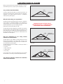
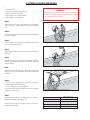
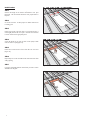
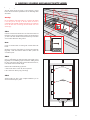
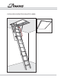
INSTALLATION INSTRUCTION FOR ATTIC LADDER
INSTALLERS, CARPENTERS, CONTRACTORS
- Read all warning notes. Warning notes contain
important safety tips.
- In order to assure safe use of the attic ladder,
proceed according to the installation instruction.
- The attic ladder is not safe to use, unless it is
completely installed according to the following
instructions.
Table of content
I.
Important issues to consider . . . . . . . . . . . . . . . . . . . . . . . . . . . . . . . . . . . . . . . . . . . . . . . . . . . .pages 2
- are you able to install attic ladder? . . . . . . . . . . . . . . . . . . . . . . . . . . . . . . . . . . . . . . . . . . . . .pages 2
- will attic ladder satisfy your expectations? . . . . . . . . . . . . . . . . . . . . . . . . . . . . . . . . . . . . . . . .pages 2
- does the construction of your ceiling enables installation of the attic ladder? . . . . . . . . . . . . .pages 2
II.
Your package should contain . . . . . . . . . . . . . . . . . . . . . . . . . . . . . . . . . . . . . . . . . . . . . . . . . . .pages 3
III. Required manpower, tools and materials . . . . . . . . . . . . . . . . . . . . . . . . . . . . . . . . . . . . . . . . . .pages 3
IV. Finding a suitable locations for installation . . . . . . . . . . . . . . . . . . . . . . . . . . . . . . . . . . . . . . . . .pages 4
V.
Cutting a hole in the ceiling . . . . . . . . . . . . . . . . . . . . . . . . . . . . . . . . . . . . . . . . . . . . . . . . . . . .pages 5
VI. Cutting the ceiling joists . . . . . . . . . . . . . . . . . . . . . . . . . . . . . . . . . . . . . . . . . . . . . . . . . . . . . . .pages 6
VII. Framing the installation opening . . . . . . . . . . . . . . . . . . . . . . . . . . . . . . . . . . . . . . . . . . . . . . . . .pages 7
- installing the single headers . . . . . . . . . . . . . . . . . . . . . . . . . . . . . . . . . . . . . . . . . . . . . . . . . . .pages 7
- double headers . . . . . . . . . . . . . . . . . . . . . . . . . . . . . . . . . . . . . . . . . . . . . . . . . . . . . . . . . . . .pages 8
- installation of stringers . . . . . . . . . . . . . . . . . . . . . . . . . . . . . . . . . . . . . . . . . . . . . . . . . . . . . . .pages 9
VIII.Installation of the temporary support boards . . . . . . . . . . . . . . . . . . . . . . . . . . . . . . . . . . . . . . .pages 9
IX. Positioning the attic ladder . . . . . . . . . . . . . . . . . . . . . . . . . . . . . . . . . . . . . . . . . . . . . . . . . . . .pages 10
X. Shimming, squaring and nailing the attic ladder . . . . . . . . . . . . . . . . . . . . . . . . . . . . . . . . . . . .pages 11
XI. Trimming the attic ladder legs . . . . . . . . . . . . . . . . . . . . . . . . . . . . . . . . . . . . . . . . . . . . . . . . . .pages 12
1
I. IMPORTANT ISSUES TO CONSIDER
Before you start any work read carefully all instructions, in order to
make sure that you have a proper spot for installation and tools.
rafter
Are you able to install attic ladder?
ceiling joist
In order to install this attic ladder, you need to know how to cut
wood and use framing square. Not being able to do the above,
installation of this product should be done by a professional
installer (refer to yellow pages).
Will attic ladder satisfy your expectations?
The attic ladder has been designed only for home use. Installation
of this product in commercial buildings can be obstructing to
existing building codes. Before installation of this product consult
with Fire Department or your local building inspector.
Maximum load of the attic ladder is 325 LB.
Fig.1. Typical roof construction
WARNING! DO NOT CUT THIS TYPE OF
CONSTRUCTION (FIG. 2, 3) WITHOUT PRIOR
CONSULTATION WITH AN ARCHITECT.
The attic ladder has been designed to be installed in room where
the ceiling height is in the range described on the packaging. This
product should not be installed if the ceiling height does not fit in
the range described on the product's label. Modifications of the
attic ladder can be dangerous.
rafter
Does the construction of your ceiling enables
installation of the attic ladder?
The attic ladder can be installed in buildings with typical wood
framed ceiling (Figure1). You should never cut any of the
constructing elements of the ceiling without prior consultation with
an architect (refer to yellow pages).
The attic ladder should not be installed in chosen spot if there is
one of the following:
ó air ducts
ó metal constructions
ó cement ceiling
ó drop ceiling
brace
Fig.2. Typical construction of the roof with braces connected to the
ceiling joists.
rafter
If your ceiling has one of the above elements you can not install
the attic ladder. In this case you should seek professional help.
The following instruction describes the installation
method of the attic ladder.
2
ceiling joist
Fig.3. Truss roof frame.
ceiling joist
II. YOUR PACKAGE SHOULD CONTAIN:
ó Attic ladder fully assembled and ready for installation. You should not dismantle assembled product for installation
ó Control rod
Prior to installation inspect the product for any cracks in the wood. Make sure that the metal elements are not damaged and securely
fastened.
III. REQUIRED MANPOWER, TOOLS AND MATERIALS
Manpower
ó 2 people (one must be able to lift 65 LB and carry it in to the attic)
Materials
ó few pieces of joist-sized lumber
ó 2 boards 1x4x36Ē for temporary support
ó few boards for working platform in the attic space
ó wood shim stock
ó 20d sinker nails
ó 4Ē screws for wood
Stepladder
Stepladder should be long enough to allow you to enter the overhead space. Make sure that the ladder will withstand your weight +65 Lb.
WARNING
You should be extremely causious while climbing the ladder, other person should be holding the ladder preventing it from tipping over.
Tools
ó flashlight
ó claw hammer
ó pencil
ó hand saw
ó tape measure
ó framing square
ó power drill
ó 1/8Ē drill bit
ó tools to cut opening in the ceiling
Safety equipment
ó gloves
ó safety goggles
ó dust mask
3
IV. FINDING A SUITABLE LOCATION FOR INSTALLATION
Before you begin:
make sure that you have required tools, manpower, and the
construction of the ceiling is suitable for installation of the attic
ladder.
Look for a space free from obstacles and dangers. Make sure that
the space will allow proper installation and use of the attic ladder.
Make sure that the lenght ot the attic ladder is suitable for your
ceiling height (fig.4, table 1).
FC
STEP 1
Choose potential installation spot. Check dimension of the
required opening, refer to the label or table 2 on page 5.
If the attic ladder will be installed in the garage consider the
location of parked cars.
STEP 2
Check the swing clearance. Figure 4 and table 1.
LS
SC
STEP 3
Check the landing space, so that both legs rest on the floor. Figure
4 table 1.
STEP 4
If the attic ladder will fit between the ceiling joists and there is no
need for cutting the joists proceed to step 7 ďFraming the installation
openingĒ page 7-9.
If it is necessary to cut the ceiling joist proceed to step 6 ďCutting
the ceiling joistsĒ page 6.
STEP 5
Go in to the attic space and locate the spot for installation.
You can find this location by listening for tapping from below or
measure the space below and in the attic area.
STEP 6
In the installation spot you should do the following:
a) check if there is enough room to work during the installation
b) make sure there are no obstacles (ie. air ducts, electrical
installations, etc.) in the attic area disabling safe installation and
use of the attic ladder.
Warning
In order to check the attic area for the above mentioned obstacles
and dangers put on a dust mask, safety goggles, gloves and proper
clothes to prevent cuts caused by mineral wool. Next, slowly lift up
the layer of insulation, do not inhale dust and other particles which
might be dangerous to your health.
Step 7
If in the chosen spot you find any obstacles, you should find another
spot for installation or contact professionals to remove the obstacle
(refer to yellow pages).
4
FC floor ceiling height
LS landing space
SC swing clearance
Fig.4. Characteristics of the attic ladder.
MODEL
SC
LS
FC
LWS-P 22/47
67Ē
58Ē
7í4íí ų 8í10íí
LWS-P 25/47
67Ē
58Ē
7í4íí ų 8í10íí
LWS-P 22/54
80Ē
64Ē
8í10íí ų 10í
LWS-P 25/54
Table 1
80Ē
64Ē
8í10íí ų 10í
WARNING!
For your own safety do not sit on the ceiling nor the insulation - it
was not design to carry load. Only the ceiling joists can
withstand your weight. Mind sharp nails sticking out of the
ceiling's construction. Do not nail anything in to the ceiling that
can conduct electricity until you are sure that there are no electric
wires. Contact with electric wires can be deadly.
V. CUTTING A HOLE IN THE CEILING
Before you begin:
find a spot which is:
ó free form any obstacles in the attic area
ó free from obstacles in the ceiling
ó big enough to carry out the installation
ó big enough to use a step ladder
WARNING!
Do not cut, file nor nail anything to the ceiling until you are sure that the
chosen space for installation is free from dangers and other obstacles.
Contact with electric wires can be deadly.
STEP 1
Prepare the work area. Remove the furniture and cover the floor
with a drop cloth. Remove children and pets to a safe distant
area.
STEP 2
Put on the safety goggles, dust mask and gloves. These will protect
your eyes and lungs.
STEP 3
Using a hammer and a chisel make an initial hole near the center
of your chosen location (Figure 5).
Fig.5. Make an initial hole.
STEP 4
Enlarge the initial hole with a hand saw until you can see the joist
(Figure 6)
STEP 5
Trace the cutting lines on the ceiling for the installation opening.
Make sure that one of the traced lines is parallel to the ceiling joist
(Figure7, table 2).
Fig.6. Enlarge the initial hole so that you can see the joist.
Note:
Having one edge of the opening parallel to the ceiling joist will
allow to use it as part of the frame which will be needed for
installation.
STEP 6
Cut out and remove remaining part of the ceiling according to
traced lines (rectangle) while observing:
a. not to cut any joists, only the ceiling board
b. remove the ceiling board by small pieces, because the ceiling
materials can be very heavy.
Fig.7. Draw a ractangle the size of the ceiling opening.
STEP 7
If there are no joists along or across the opening go to section 7
ďFraming the installation openingĒ pg. 7-9.
If there are joists in the cut out opening proceed to section 6
ďCutting the ceiling joistsĒ.
MODEL
Ceiling opening size
LWS-P 22/47
22-1/2Ē x 47Ē
LWS-P 25/47
25Ē x 47Ē
LWS-P 22/54
22-1/2Ē x 54Ē
LWS-P 25/54
25Ē x 54Ē
Table 2
5
VI. CUTTING THE CEILING JOISTS
Before you begin
installation spot
You should now have the cut out hole in the appropriate spot.
STEP 1
ceiling joist
If the room has a ceiling in which you made the opening proceed
to step 2.
If there is no ceiling in place mark the joists according to instruction
A or B, below.
A - If the chosen location is parallel to the ceiling joists, mark the
length of the opening on the top surface of the joist as shown on
Figure 9. Do not cut the joist as marked.
Fig.8. Dotted line indicates your chosen location parallel to the joist.
installation spot
B - If the chosen location is perpendicular to the ceiling joists, mark
the width of the opening on the top surface of the joist as shown
on Figure 8. Do not cut the joist as marked.
ceiling joist
STEP 2.
Cut 2 pieces of board similar to the size of the ceiling joist, long
enough to nail them to the ceiling joists on both ends of the
opening (Figure10). These boards will provide support to joists
which will be cut out.
STEP 3
Fig.9. Dotted line indicates your chosen location perpendicular to the
joist.
Position these boards approximately 2 ft from the opening edge
(pic 10).
"
24
Note
joist support boards
The 2 ft space is required to nail the frame.
STEP 4
Note
"
24
Nex decide where you will cut the joist see Figure11. The cutting
line should be away from the actual opening twice the thickness of
the frame (usually 3 inches). This will allow to install double
headers at both ends of the joist (pic 17 pg.8).
nail or screw
Fig.10. Dotted line indicates your chosen location.
In older homes the thickness of the joist might be greater than what
is currently sold in lumber yards. In such case the cutting line
should be marked at twice the thicknesses of the material which
you will use to build the frame not the joist.
STEP 5
cut here
section of joist
to be removed
2 x the joist
thickness
cut here
Cut the joist carefully, watching not to cut the ceiling board and
making sure that the cut out joist is even and vertical (square).
2 x the joist
thickness
Fig.11. Dotted line indicates your chosen location.
6
VII. FRAMING THE INSTALLATION OPENING
Before you begin
The distance between the joists should be the same as the width of installation opening. All cut joists must be attached to the joists that have not
been cut.
WARNING!
For your own safety mind all dangerous elements above your head. Do not sit on the ceiling - it is not designed do carry load.
Only joists will withstand load. In order to make a working area place several boards across the ceiling joists.
Installing the headers
If none of the joists were cut proceed to section ďsingle headerĒ.
If one or more joists were cut proceed to section ďdouble headersĒ
on page 8.
P
Single headers
STEP 1
Measure the distance between the ceiling joists. The measurement
should be done perpendicular to the joist (Figure12).
STEP 2
Fig.12. P- Distance between the ceiling joists.
Cut 2 boards for headers to the measured length. Use timber
material similar in size to the joists.
header
STEP 3
Position the header at one end of the installation opening
(Figure13). The header must tightly fit between the joists. If
needed use a hammer to position the header.
ceiling joist
nails
Step 4
Align the header at 90o angle to the joists and drive 3 nails (16D)
at each end.
Fig.13. Nail the header at both ends.
header
STEP 5
Position the second header 47Ē apart from the first one for LWSP 22/47, LWS-P 25/47 or 54Ē for LWS-P 22/54, LWS-P 25/54
and repeat step 4 (Figure 14).
7)
/4
25 4)
S-P
/5
LW P 25
7;
/4 LWS
22
;
S-P 2/54
2
(LW
-P
"
47 " (LWS
54
STEP 6
ceiling joist
The frame must have four sides where the headers are two of them.
If the ceiling joists are positioned as the other two sides check the
angles by measuring the diagonals. Both measured dimensions
should be within 1/8Ē to consider them equal.
Proceed to section 8 ďinstallation of temporary support boardsĒ.
If the ceiling joists do not make the other two sides of the frame,
you should install one or two wooden elements in order to make
the frame in the ceiling opening. Proceed to section ďinstallation of
stringersĒ.
D1 D2
nails
D1=D2
header
Fig.14.
7
Double headers
STEP 1
P
Measure the length of the header ďPĒ between uncut joists
(Figure15). The measurement should be done perpendicular to
the joists.
STEP 2
Cut to size 4 headers. For that purpose use timber similar in size
to existing joists.
STEP 3
Position one header at the end of the cut out joist (Figure16). It
must fit tightly between the uncut joists. If needed use a hammer
to set the header in the appropriate place.
Fig.15. P- Distance between the ceiling joists.
STEP 4
first header
Square the header to one joist and drive 3 nails (16d) on both
ends and to the cut joist (Figure 16).
STEP 5
Position the second header in front of the first one and nail it
(Figure 17).
nails
cut ceiling joist
STEP 6
Repeat steps 3-5 in order to install headers at the other side of the
ceiling opening.
STEP 7
Fig.16.
In order to install other elements of the frame proceed to section
ďinstallation of stringersĒ.
second header
nails
cut ceiling joist
Fig.17.
8
Installation of stringers
STEP 1
Measure the length of the stringer ďWĒ between the cross-beams
(Figure18). The measurement should be perpendicular to the headers.
W
STEP 2
Cut the stringer to size. Use timber similar in size to the existing
ceiling joists.
STEP 3
If the joists do not make up the other two sides of the frame, you
need to install one more stringer of the same length as before. On
Figure 18 only one stringer is needed because the ceiling joist
makes up one side of the frame.
Fig.18. W- Distance between the ceiling joists.
header
STEP 4
Position the stringer (or stringers) along the unframed side if the
ceiling opening (Figure19). The inside dimensions of the frame
should be equal to the ceiling opening (see product label or table
2 on page 5.
header
D2
D1
D1=D2
STEP 5
In order to install stringers to the headers you should use nails long
enough to go through both cross-beams and enter the stringer at least
1Ē. In most cases it should be 20d nail 4Ē long. Square the stringer
and drive 3 nails at each end through the double header. Both
measured dimensions should be within 1/8Ē to consider them equal.
stringer
nails
Fig.19.
VIII. INSTALLATION OF THE TEMPORARY SUPPORT BOARDS
Before you begin:
The frame around the ceiling opening must be finished.
CAUTION: Check the distance between the temporary support
boards, it must be equal to the values given in table 3 and fig. 20.
The attic ladder can fall down if the temporary support boards are
spaced incorrectly.
STEP 1
Using 4 nails or screws attach the temporary support board 1Ēx
4Ēx 36Ē where the hinged end of the ladder will be installed. This
temporary support board must form a 1/4Ē ledge across the
ceiling opening (Figure 20).
Note:
MODEL
X - distance between headers
LWS-P 22/47
46-1/16Ē
LWS-P 25/47
46-1/16Ē
LWS-P 22/54
52-7/8Ē
LWS-P 25/54
Table 3
52-7/8Ē
It is recommended to use double headed nails which can be easily
removed.
STEP 2
Using 4 nails or screws, attach the second temporary support at
the other end of the opening so that the temporary support boards
are ďXĒ inches apart (table 3).
1/4"
X
X
temporary support boards
1/4" ledge along hinged side
X
screws or nails
temporary
support boards
Fig.20. Installation of temporary support boards.
9
IX. POSITIONING THE ATTIC LADDER
Before you begin:
You must have temporary support boards installed at both ends
(Figure20)
STEP 1
Take out the control rod (Figure21). Leave the control rod for the
person working below the ceiling.
STEP 2
One person must go in to the attic space while the other person
stays below.
Fig.21.
WARNING!
The attic ladder can not be used to climb in to the overhead space
until it is permanently installed to the previously made frame, and
until the legs are trimmed to the appropriate length. Therefore in
some cases the person in the overhead space must remain there
until the end of installation.
headers
1/4"
shim
casement
X
STEP 3
Make sure that people other than installers are kept clear from the
working area.
X
1/4"
temporary support board
STEP 4
Carefully position the attic ladder on the temporary support so that
the hinged end rests on the 1/4Ē ledge. The person working in the
overhead space is blocking the attic ladder with shims, preventing
it from falling down from the ledges (Figure22). Shims should be
inserted between the case of the attic ladder and the headers at
the opening end. Make sure that the attic ladder rests on the
temporary support boards.
Fig.22.
STEP 5
2
Open the attic ladder using the control rod by turning it 90o (arrow 1)
counterclockwise (Figure23). Pull the lid until fully open and until
the blocking mechanism is engaged (arrow 2).
1
WARNING!
Too abrupt opening of the lid can cause the attic ladder to slip out
from the temporary support boards and fall down.
Do not lift up the lid using the control rod until the attic ladder is
completely installed. This can cause the attic ladder to slip out from
the temporary support boards and fall down.
Do not open the attic ladder by pushing the lid from the above. The
tension of the spring rapidly changes, you could loose your balance
and fall down.
Do not open the attic ladder by force nor change the positioning of
the temporary support boards while the ladder is in place. If the lid
is blocked by the temporary support disabling you to open the attic
ladder you should remove the attic ladder and re install the
temporary support boards.
10
Fig.23.
Warning!
Do not unfold legs of the attic ladder yet. Use of the attic ladder is
not safe yet. Do not step on the attic ladder nor leave it unattended
until completely installed and both legs are adjusted to rest on the
floor. This can damage the attic ladder and cause severe injury.
X. SHIMMING, SQUARING AND NAILING THE ATTIC LADDER.
Before you begin:
The attic ladder should be resting on the temporary support
boards. The lid should be openable but do not unfold legs of the
attic ladder.
D1=D2
D1
D2
Warning!
Do not unfold legs of the attic ladder yet. Use of the attic ladder
is not safe yet. Do not step on the attic ladder nor leave it
unattended until completely installed and both legs are adjusted to
rest on the floor. This can damage the attic ladder and cause
severe injury.
shim
STEP 1
Insert the wooden shims between the case of the attic ladder and
the frame (as shown on Figure24) and until it is square in the frame
you built. The shims should be inserted from the top and bottom
and not extend below the ceiling surface.
shim
Note:
Use of an oversized shims can damage the casement of the attic
ladder.
Check the squareness of the frame by measuring the diagonals
(Figure24). Both measurements should be within 1/8Ē to be
considered square.
Fig.24.
STEP 2
Using a 1/8Ē drill bit, pre drill nail locations in the ladder casing
(Figure25). Do not drill through joists and headers. Drilling should
be done on the longer sides of the casement where the shims are,
in the middle of the casementís height.
shims
Nail the attic ladder following instructions:
a. Drive 6 nails 20d or screws 4Ē, check squareness
b. Be careful not to hit the spring or the hinge
STEP 3
Trim the sticking out shims. Upon complete installation you can
also remove the temporary shims.
nail
through
shims
Fig.25. View from the top.
11
XI. TRIMMING THE ATTIC LADDER LEGS
Before you begin:
The attic ladder should be properly shimmed and securely nailed
to the frame in the proper location.
Measure A and B
WARNING!
Use of the attic ladder is not safe yet.
Do not unfold the attic ladder yet. Do not step on the attic ladder
nor leave it unattended until completely installed and both legs are
adjusted to rest on the floor. This can damage the attic ladder and
cause severe injury.
STEP 1
Make sure that the lid is fully open. Unfold legs of the attic ladder
and fold the bottom section as shown on Figure 26.
Note:
A will be shorter than B
Fig.26.
STEP 2
Loosen screws as shown by the arrow 1 and move the steps away
from the lid as shown by arrow 2 (Figure27).
STEP 3
1
Tighten the previously loosened screws as shown by arrow 3
(Figure28).
WARNING!
Upon completion of these tasks the distance between the steps
and the lid should remain constant. Otherwise this can cause
damage to the attic ladder and cause severe injuries.
2
1
STEP 4.
2
Using a straight edge measure the distance ďAĒ and ďBĒ as shown
on Figure 26.
This measurement should be very precise in order to ensure proper
trimming of the legs.
Fig.27.
ATTENTION
Measure the distance ďAĒ and ďBĒ on both sides of the attic ladder.
The distance may not be the same on both sides of the attic ladder.
Left leg
3
Right leg
A
3
B
Fig.28.
12
STEP 5
Measure the ďAĒ and ďBĒ distance from the top edge of the bottom
section of the attic ladder and mark it on both legs (Figure29).
Trim lines must be accurate in order to avoid trimming the legs too
short.
Mark A and B
Note:
A will be shorter than B
WARNING!
If the trimming line is marked along the rung, you should reposition
the full run of steps where it is attached to the lid. The trimming line
must not be in line with the rung (Figure30). Next repeat
measurements ďAĒ and ďBĒ starting from step 4.
STEP 6
Trim the legs along the trimming lines. Trim the corners of the legs
perpendicular to side ďBĒ but no more than 1/ 2Ē from the corner
(Figure29). Using attic ladder with too short legs will damage the
ladder and can cause severe injuries.
Fig.29.
STEP 7
Check for proper trimming of the legs, by unfolding the full run. The
ladder should look like on Figure 31. There should be no gaps
between the metal hinges and the feet should be flush with the floor.
ATTENTION:
Gaps between the metal hinges mean that the feet are not
properly trimmed (Figure32 and 33). Do not climb the attic ladder
if there are visible gaps between the metal hinges. This can cause
damage to the attic ladder and and result in serious injury.
If the attic ladder looks like on Figure 32, one or both legs are too
long. Send or trim the feet until there are no gaps between the
metal hinges and both legs are flush with the floor.
Fig.30.
If the legs look like on Figure 33, both legs are too short. If there
are no gaps between the metal hinges but one leg is too short, use
of the attic ladder is not safe. If the legs are trimmed too short do
not use the attic ladder.
Contact your local dealer.
STEP 8
Remove the temporary support boards.
Congratulations! Your installation is complete!
Fig.31. Properly instaled attic ladder
gap
gap
Fig.32. Legs too long.
Fig.33. Legs too short.
13
FAKRO AMERICA, L.L.C.
311 W. Laura Dr
Addison, IL 60101, USA
tel. (630) 543-1010
fax. (630) 543-1011
e-mail: [email protected]
www.fakro.info
www.fakro.com
“FAKRO” and the FAKRO logo are registered trademarks of FAKRO Group.
All specifications are subject to change without prior notice.
©2003 FAKRO GROUP
IMSS-USA-A4GB-09.04.2003/K