1
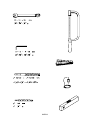
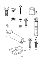
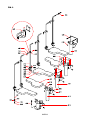
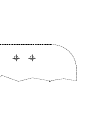
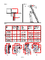
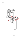
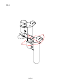
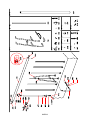
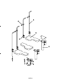
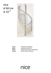
KARINA
English
Español
ASSEMBLY INSTRUCTION
INSTRUCCIONES PARA EL ENSAMBLAJE
KARINA
English
Before starting the assembly process, unpack all components of the staircase. Lay them out on a large
surface and check the quantity of all the pieces, by consulting the table (TAB.1: A = Code, B = Quantity).
Inside the staircase box you will also find a DVD which we suggest watching before proceeding to assemble.
For customers in the USA there is a customer assistance number 1-888 STAIRKT, which you can telephone
in case of problems.
Assembly
1. Carefully measure the floor-to-floor height.
2. Calculate the rise:
1) subtract 22 cm (8 5/8”) from the floor-to-floor height you measured,
2) divide this value by the rises number minus one.
Example: for the measured floor-to-floor height of 268 cm and a staircase with 12 rises;
(268 - 22) / (12 - 1) = 22,36
(8’3 1/2” - 8 5/8”) / (12 - 1) = 8 3/4”.
3. Determine the position of the support N19 (fig. 1) keeping in mind two points:
1) the rise, calculated previously, also contains the tread depth (L19 or L20) (fig. 2).
2) position the support N19 keeping in mind the opening feature (fig. 3).
4. Drill with the drill bit D. 14 mm (9/16”).
5. Assemble on the floor, in a straight line, the supports N19, N18, N17 and N16 keeping in mind the calculated rise. Use the parts C15, B71 and B75 (fig. 1). Tighten sufficiently keeping in mind that the supports N19, N18, N17 and N16 still have to rotate for the configurations B, C, D.
6. Lift and position the structure with the support N19 which has to touch the floor (fig. 4). If the stair place is too tight, it is suggested to rotate some supports.
7. Tighten the support N19 completely, by using the part C39 (fig. 1).
8. Place on the floor, in sequence, one left tread (L19), one right tread (L20) and so on. Now determine which will be the first tread from the top (fig. 3).
9. Cut along the shape (fig. 7 - center page).
10.Decide where to assemble the railing (inside or outside) (fig. 3) and pierce the treads (L19, L20) with the drill bit D. 6,5 mm (1/4") using the template only for the straight sides. To find the fixing point on the short side of the winding treads (L19, L20) maintain the same distance as the one between the balusters (C12) to assemble on the long side of the tread (fig. 3).
11.Assemble and tighten the parts F23 by using the parts C14, B83, B86, C13, B02 (fig. 1).
12.Fasten element N26 to the treads L19 and L20 using the screw C40.
13.Finally attach the treads (L19, L20) starting from the bottom N16 up to the support N19, using the elements C40 (fig.1).
14.1.The configuration A (straight) doesn’t need any further changes (fig. 3).
2. The configurations B or C need a rotation of 13° (fig. 3).
3. The configuration D needs a rotation of 18° (fig. 3).
15.To rotate the supports of 13° or 18° you have to proceed as follows:
a. Set out with a pencil, at the connection point of two supports, two vertical lines at a distance
of 9 mm (23/64”) (to rotate 13°, configuration B or C) (fig. 5) or 13 mm (33/64”) (to rotate 18°, configuration D) (fig. 6).
b. Loosen the parts C15, one support by one, starting from the top and rotate until one of the lines matches the one of the top according to the direction of rotation.
c. Tighten the parts C15 completely (fig. 1).
Assembly of the Railing
16.Assemble the parts C28 by using the parts C13, B02 and insert them into the balusters (C12) (fig. 1).
17.Insert the balusters (C12) into the parts F23, blocking them by the part B02.
18.The first balusters (C12) of the long side of every tread (L19, L20) have to be cut.
19.Tighten the part C28 completely, by using the part B02 (fig. 1). For a correct assembly twist the key at about 90° from the contact point.
KARINA
Final Assembly
20.Control the vertical line of the whole stair and, if necessary, correct it by moving the support N16 (fig. 1).
21.Disassemble the first tread (L19 or L20) and drill the floor with a D. 14 mm (35/64") tip in relation to the present holes on the support N16 (fig. 1).
22.Insert the parts C39 and tighten completely (fig. 1).
23.Reassemble the first tread (L19 or L20) and fix on the floor, in relation to the first baluster (C12), the part F01, by drilling with a D. 8 mm (5/16") tip. Use the parts B11, B12, B83 and B02 (fig. 1).
24.Insert the baluster (C12) and tighten the part B02 (fig. 1).
KARINA
Español
Antes de empezar el ensamblado de la escalera, desembalar todas las piezas de la escalera. Colocarlas de
manera que pueda verificarse las cantidades (TAB. 1: A = Código, B = Cantidad).
Os aconsejamos que veáis previamente el DVD que encontraréis con el material sumistrado.
Para el mercado estadounidense, para cualquier inconveniente, llamar al número de asistencia al cliente
1-888 STAIRKT.
Ensamblaje
1. Medir con cuidado la altura de pavimento a pavimento.
2. Calcular el valor de la tabica:
1) restar 22 cm (8 5/8”) al valor de la altura de pavimento a pavimento.
2) dividir el resultado por él numero de contrahuellas menos una.
Ejemplo: para una altura de pavimento a pavimento 268 cm y una escalera de 12 contrahuellas;
(268 – 22) / (12 - 1) = 22,36
(8’3 1/2“- 8 5/8“) / (12 - 1) = 8 3/4“
3. Hallar la posición donde fijar el soporte N19 (fig. 1) teniendo en cuenta dos puntos:
1) la contrahuella, anteriormente calculada, que incluye también el espesor del peldaño (L19 o L20) (fig. 2). 2) colocar el soporte N19 teniendo en cuenta el tipo de hueco (fig. 3).
4. Taladrar con broca de Ø 14 mm (9/16”).
5. Ensamblar sobre el pavimento, con desarrollo rectilíneo, los soportes N19, N18, N17 y N16 teniendo en cuenta la altura anteriormente calculada. Utilizar los elementos C15, B71 y B75 (fig. 1). Apretar suficientemente, teniendo en cuenta que los soportes N19, N18, N17 y N16 deben de girar para las configuraciones B, C y D.
6. Levantar y colocar la estructura con el soporte N19 en contacto con el forjado (fig. 4). En el caso que el hueco sea estrecho aconsejamos girar algún soporte.
7. Fijar definitivamente el soporte N19, utilizando el elemento C39 (fig. 1).
8. Repartir sobre el pavimento, seguidos, un peldaño izquierdo (L19), un peldaño derecho (L20) y seguir así. Determinar, en este punto, cual va a ser el primer peldaño de arriba (fig. 3).
9. Recortar la plantilla (fig. 7 - página central).
10.Decidir donde colocar la barandilla (interior o exterior) (fig. 3) y taladrar los peldaños (L19, L20) con una broca de Ø 6,5 mm (1/4") utilizando la plantilla solamente para los tramos rectos. Para determinar el punto de fijación en el lado corto y el lado largo de los peldaños en curva (L19, L20) respetar una distancia igual a la de los barrotes (C12) montados sobre el lado recto (fig. 3).
11.Ensamblar y fijar los elementos F23 utilizando los elementos C14, B83, B86, C13, B02 (fig.1)
12.Fijar el elemento N26 en los peldaños L19 y L20 utilizando el tornillo C40.
13.Fijar definitivamente los peldaños (L19 y L20) partiendo desde abajo (N16) hasta el soporte N19, utilizando los elementos C40 (fig. 1).
14.1. La configuración A (rectilínea) no necesita ninguna modificación (fig. 3).
2. Las configuraciones B o C necesitan una rotación de 13 º (fig. 3).
3. La configuración D necesita una rotación de 18 º (fig. 3).
15.Para girar los soportes de 13º o 18º proceder como se indica:
a. Realizar un trazo con un lápiz, en el punto de unión de dos soportes, dos líneas verticales con una distancia de 9 mm (23/64”) (para girar 13º, configuración B o C) (fig. 5) o 13 mm (33/64”) (para girar 18º, configuración D) (fig. 6).
b. Aflojar los elementos C15, un soporte a las ves, empezando desde arriba y girar hasta hacer coincidir una línea con la otra.
c. Apretar los elementos C15 definitivamente (fig. 1).
Montaje de la barandilla
16.Ensamblar los elementos C28 utilizando los elementos C13, B02 e introducirlos en los barrotes (C12) (fig. 1).
17.Introducir los barrotes (C12) en los elementos F23, bloqueándolos con el elemento B02.
18.Los primeros barrotes (C12) del lado largo de cada peldaño (L19, L20) deben cortarse en altura.
19.Apretar definitivamente el elemento C28, utilizando el elemento B02 (fig. 1). Para una correcta KARINA
instalación girar la llave de 90° aproximadamente desde el punto de contacto.
Montaje final
20.Verificar la verticalidad de toda la escalera y si fuera necesario, corregirla desplazando el soporte N16 (fig. 1).
21.Desmontar el primer peldaño (L19 o L20) y taladrar el pavimento con una broca de Ø 14 mm (35/64") en la situación de los orificios presentes en el soporte N16 (fig. 1).
22.Introducir los elementos C39 y apretar definitivamente (fig. 1)
23.Volver a montar el primer peldaño (L19 o L20) y fijar al pavimento, el elemento F01, a la altura del primer
barrote, taladrando con una broca Ø 8 mm (5/16"). Utilizando los elementos B11, B12, B83 y B02 (fig. 2).
24.Introducir el barrote (C12) y apretar el elemento B02 (fig. 1).
KARINA
TAB 1
A
B
B02
62
B11
2
B12
2
B71
20
B75
40
B83
62
B86
30
C12
15
C13
60
C14
30
C15
20
C28
15
C39
4
C40
55
F01
2
F23
30
L19
6
L20
5
N16
1
N17
1
N18
8
N19
1
N26
11
KARINA
KARINA
FIG. 1
KARINA
FIG. 7
KARINA
FIG. 2
FIG. 4
FIG. 3
KARINA
FIG. 5
KARINA
FIG. 6
KARINA
KARINA
English
PRODUCT DETAILS
Español DATOS DE IDENTIFICACIÓN
3
4
2
4
1
KARINA
GB)
product details
trade name: KARINA
type: flight with alternate treads and rotation without interruption
used materials
STRUCTURE
description
composed by metallic elements (1) assembled between themselves by bolts
materials
Fe 370
finishing
epoxy powder coated in furnace
TREADS
description
treads (2) shaped in wood assembled to the structure by bolts
materials
beech
finishing
water-base colour
polyurethane undercoat
polyurethane finishing
RAILING
description
composed by vertical balusters (3) in metal fixed to the treads (2)
materials
balusters: Fe 370
fixings (4): nylon
finishing
balusters: epoxy powder coated in furnace
CLEANING
clean with a soft wet cloth, without any product containing solvents or abrasive materials.
MAINTENANCE
about 12 months after the installation date, check the tightening of bolts on the various components. special
maintenance must be done by skilled staff. please contact the provider.
USE PRECAUTION
avoid any improper use that is not in accordance with the product. possible violations or installations which don’t
comply with the providers instructions can invalidate the agreed product conformities.
KARINA
E)
datos de identificación del producto
denominación comercial: KARINA
tipo: escalera abierta con peldaños de paso alternado y rotación de las rampas con pendiente
materiales empleados
ESTRUCTURA
descripción
compuesta por elementos (1) metálicos ensamblados unos con otros mediante pernos
materiales
Fe 370
acabado
barnizado en horno con polvos epoxídicos.
PELDAÑOS
descripción
peldaños (2) de madera perfilados y ensamblados a la estructura mediante pernos
materiales
haya
acabado
barniz al agua
imprimación poliuretánica
acabado poliuretánico
BARANDILLA
descripción
compuesta por barrotes (3) verticales de metal fijados a los peldaños (2)
materiales
barrotes: Fe 370
fijaciones (4): nylon
acabado
barrotes: barnizado en horno con polvos epoxídicos
LIMPIEZA
limpiar con un trapo suave humedecido con agua y sin ningún producto que contenga disolventes o materiales abrasivos.
MANTENIMIENTO
transcurridos unos 12 meses desde la fecha de instalación, comprobar que los tornillos que fijan las distintas partes sigan
bien apretados. el mantenimiento extraordinario deberá llevarlo a cabo personal cualificado. ponerse en contacto con el
fabricante.
PRECAUCIONES DE USO
evitar usos impropios y no conformes con el producto. eventuales manipulaciones o instalaciones que no cumplan con
las instrucciones del fabricante pueden menoscabar las cualidades certificadas en las pruebas de conformidad a las que
previamente fue sometido el producto.
KARINA
For further information pertaining to these assembly instructions, additional parts or general
questions regarding products or assembly please call, fax or email us at:
ARKE' by Fontanot
Albini & Fontanot SpA
75 Jackson Street, Suite 303
Newnan, GA 30263
Toll Free: (888) 782 - 4758
Phone: (770) 683 - 7200
Fax: (770) 683 - 7209
Email: [email protected]