1
$QQXDO0DLQWHQDQFH
/XEULFDWHDOOPRYLQJSDUWVRIWKHGRRUZLWKOLJKWKRXVHKROG
RLOLQFOXGLQJ
D /LIWFDEOHVDWWKHERWWRPEUDFNHWEXWWRQ
E %HDULQJRIWKHVKHDYHV
F /RFNKDUGZDUHZKHUHVXUIDFHVWXUQRUVOLGH
G )XOOOHQJWKRIWRUVLRQVSULQJWRUHGXFHIULFWLRQEHWZHHQ
FRLOV
H /XEULFDWHVWHHOUROOHUV'2127OXEULFDWHQ\ORQUROOHUV
&KHFNIRUORRVHRUEHQWKLQJHV
D 7LJKWHQORRVHKLQJHV
E 6WUDLJKWHQRUUHSODFHEHQWKLQJHV
&DXWLRQ7RUHSODFHEHQWKLQJHVRUEURNHQUROOHUV
'RRUPXVWEHORFNHGDQGLQWKHGRZQSRVLWLRQ
1RPRUHWKDQKLQJHLVWREHUHPRYHGIURPWKHGRRUDWDQ\
JLYHQWLPH
8QGHUQRFLUFXPVWDQFHVVKRXOG\RXORRVHQRUUHPRYHWKH
ERWWRPEUDFNHWZLWKRXWGLVHQJDJLQJWKHVSULQJWHQVLRQ)ROORZ
LQVWUXFWLRQVIRUUHPRYLQJH[WHQVLRQVSULQJV
&KHFNUROOHUIRUEURNHQZKHHOVEHQWVKDIWVRUZRUQRXW
EHDULQJV
&KHFNWKHGRRUDQGWUDFNVXSSRUWVIRUORRVHRUPLVVLQJ
EROWVVFUHZVHWF%HFDUHIXOQRWWRRYHUWLJKWHQ
&KHFNWKHH[WHQVLRQFDEOHV$UHWKH\UXQQLQJSURSHUO\LQ
WKHVKHDYHV"&KHFNIRUZHDURIWKHFDEOHDWWKHERWWRP
EUDFNHWEXWWRQ
&KHFNIRUEHQWWUDFN,IEHQWFDOODQDXWKRUL]HG
SURIHVVLRQDOGHDOHU
([WHQVLRQVSULQJKDUGZDUHLQFOXGLQJVSULQJVFDEOHV
VKHDYHVVKHDYHIRUNVERWWRPEUDFNHWVDQGFRQWDLQPHQW
FDEOHVVKRXOGEHDGMXVWHGRUUHSDLUHGRQO\ZKHQWKH
VSULQJWHQVLRQLVUHOHDVHGWKHGRRUPXVWEHRSHQ7KHVH
UHSDLUVVKRXOGEHPDGHE\DTXDOL¿HGGRRUWHFKQLFLDQRU
DPHFKDQLFDOO\H[SHULHQFHGSHUVRQZLWKSURSHUWRROVDQG
LQVWUXFWLRQV
,I\RXUGRRUKDVWRUVLRQVSULQJVWKHVSULQJDVVHPEO\DQG
ZRRGDQFKRUSDGVKRXOGRQO\EHDGMXVWHGRUUHSDLUHGE\D
SURIHVVLRQDOGRRUWHFKQLFLDQ
:D[LQJWKH'RRU
&RDVWDODQG+DUVK(QYLURQPHQWV
)RUFRDVWDODQGKDUVKHQYLURQPHQWVLWZLOOEHQHFHVVDU\
WRZD[WKHIURQWVLGHRIWKHGRRUIROORZLQJLQVWDOODWLRQ
6HOHFWDJRRGTXDOLW\FDUZD[DQGDSSO\DFFRUGLQJWRZD[
PDQXIDFWXUHU¶VLQVWUXFWLRQV:D[VKRXOGEHDSSOLHGDW
OHDVWWZLFHD\HDULPPHGLDWHO\DIWHUFOHDQLQJVHHFOHDQLQJ
LQVWUXFWLRQVDERYH
).34!,,!4)/.-!).4%.!.#%
)NSULATED3TEEL2ESIDENTIAL'ARAGE$OOR)NSTRUCTIONS
-ODEL???????????????????? 3ERIAL.O ?????????????????????????????????????????
Glass, Plexiglass, Stained Look, Leaded
6WXGLR6HULHV3OH[LJODVV6WDLQHG/RRN
Look,
Brilliance, and Studio Series Windows
Cleaning
and Care Instructions
/HDGHG/RRNDQG'HVLJQHU&ROOHFWLRQ
:LQGRZV&OHDQLQJ&DUH,QVWUXFWLRQV
Clean
with a mild solution of a dishwashing detergent
and
a soft cloth. After cleaning, rinse thoroughly. DO
&OHDQLQJ&OHDQZLWKDPLOGVROXWLRQRIDGLVKZDVKLQJ
NOT
use any ammoniated, abrasive, or solvent-based
GHWHUJHQWDQGDVRIWFORWK$IWHUFOHDQLQJULQVHWKRURXJKO\'2
cleaners
of any kind.
127XVHDQ\DPPRQLDWHGRUVROYHQWEDVHGFOHDQHUVRIDQ\
0ROVIDEDONLABELONINTERIORDOORSURFACE
3IZE ????????????????????? Register your product online at http://warranty.clopaydoor.com
(OMEOWNERS3HOULD2ETAIN4HIS"OOKLET&OR&UTURE2EFERENCE
Installed By:
NLQG
Studio Series Windows Only:
Use
a good grade of automotive paste wax and buff with a
&DUH8VHDJRRGJUDGHRIDXWRPRWLYHSDVWHZD[DQGEXIIZLWK
soft
cloth. Windows should be cleaned and waxed at least
DVRIWFORWK:LQGRZVVKRXOGEHFOHDQHGDQGZD[HGDWOHDVW
once
annually or more often based on the atmospheric
DQQXDOO\RUPRUHRIWHQEDVHGRQWKHDWPRVSKHULFFRQGLWLRQV
conditions
where installed.
ZKHUHLQVWDOOHG
Caution:
Use care when handling decorative windows to
&DXWLRQ'RQRWVFUDSHRUVFUDWFK
avoid scraping or scratching the surface.
127(0LQRUVFUDWFKHVRUVFXIIVDUHQRWFRQVLGHUHGGHIHFWV
NOTE:
Minor scratches or scuffs are not considered
DQGZLOOQRWEHFRYHUHGXQGHUWKHZLQGRZZDUUDQW\
defects and will not be covered under the window warranty.
5HSODFHPHQW3DUWV
5HSODFHPHQWSDUWVDUHDYDLODEOHIURPDQDXWKRUL]HG
SURIHVVLRQDOGHDOHURUDEXLOGLQJVXSSO\UHWDLOHU:KHQRUGHULQJ
UHSDLUSDUWVDOZD\VSURYLGHWKHIROORZLQJSDUWQDPHPRGHO
QXPEHUDQGGRRUZLGWKDQGGRRUKHLJKW:[+)RUWKH
ORFDWLRQRIWKHDXWKRUL]HGSURIHVVLRQDOGHDOHURUDEXLOGLQJ
VXSSO\UHWDLOHUQHDUHVW\RXSOHDVHZULWHRUFDOO
&ORSD\%XLOGLQJ3URGXFWV
&RQVXPHU6HUYLFHV'HSW
1400 West Market Street
Troy, OH 45373 USA
&DOO7ROO)UHH
+RXUVRI2SHUDWLRQ(7
0RQGD\±)ULGD\$030
6DWXUGD\$030
)NSTALLED"Y
&OHDQLQJWKH'RRU
,QRUGHUWRSUHYHQWGDPDJHUXVWLQJFDXVHGE\IRUHLJQPDWWHU
DGKHULQJWRWKHGRRUWKHGRRUVKRXOGEHFOHDQHGDWOHDVW
WZLFHD\HDUQRUPDOHQYLURQPHQWVRUWLPHVD\HDUFRDVWDO
HQYLURQPHQWV7KHGRRUPD\QHHGWREHFOHDQHGPRUH
IUHTXHQWO\LIURDGVDOWDFFXPXODWHVLQDZLQWHUFOLPDWH7KHGRRU
VKRXOGEHZLSHGGRZQZLWKDPLOGKRXVHKROGGHWHUJHQWDQG
ULQVHGZLWKFOHDUZDWHU
127(%HVXUHWRFOHDQEHKLQGVWRSPROGLQJRQWKHVLGHVDQG
WRSRIGRRU
# / . 3 5 - % 2 ( / 4 , ) . % s # , / 0!9 s 2010 &ORSD\%XLOGLQJ3URGXFWV&RPSDQ\
310137015
(OURSOF/PERATION%4-ONn&RI!-0-3AT!-0-
:HZLOOUHSDLURUUHSODFHDWRXURSWLRQDQ\JDUDJHGRRUVHFWLRQRUKDUGZDUHWKDWLVGHIHFWLYHLQPDWHULDORUZRUNPDQVKLSSXUVXDQWWRWKHWHUPV
RIWKLVOLPLWHGZDUUDQW\7KLVZDUUDQW\H[WHQGVWRDQGEHQH¿WVRQO\WKHRULJLQDOSXUFKDVHURIWKHJDUDJHGRRU7KLVZDUUDQW\GRHVQRWDSSO\WR
FRPPHUFLDOLQGXVWULDORUDQ\RWKHUQRQUHVLGHQWLDOLQVWDOODWLRQ
:H ZLOO SURYLGH DW QR FRVW WR \RX VHFWLRQVVHFWLRQ FRPSRQHQWV KDUGZDUH VSULQJVVSULQJ FRPSRQHQWV RU ZLQGRZV WR UHSDLU RU UHSODFH
GHIHFWLYHVHFWLRQVKDUGZDUHVSULQJVVSULQJFRPSRQHQWVRUZLQGRZV$OOODERUFRVWVDVVRFLDWHGZLWKWKHUHPRYDODQGUHLQVWDOODWLRQRIDQ\
UHSDLUHGVHFWLRQVHFWLRQFRPSRQHQWVKDUGZDUHRUVSULQJVSULQJFRPSRQHQWVDQGWKHLQVWDOODWLRQRIUHSODFHPHQWVHFWLRQVVHFWLRQFRPSRQHQWV
KDUGZDUHVSULQJVSULQJFRPSRQHQWVRUZLQGRZVZLOOEH\RXUUHVSRQVLELOLW\:HUHVHUYHWKHULJKWWRLQVSHFWDQGRUYHULI\DQ\FODLPHGGHIHFW
7KHDSSOLFDEOHOLPLWHGZDUUDQW\SHULRGVDUHDVIROORZV
0RGHO
3DLQW6\VWHP
GD2SP, GD2LP, GD1SP, GD1LP, /LPLWHG/LIHWLPH
GD1SU, GD1LU,
GD2SU, GD2LU
GR2SP,
GR2LP,
GR1SP,
GR1LP,
/LPLWHG/LIHWLPH
GR1SU,
GR1LU, GR2SU, GR2LU
:LQGRZV 6HFWLRQV'HODPLQDWLRQ
+DUGZDUH
6SULQJV
\UV
\UV
\UV
\UV
\UV
\UV
7HUPVDQGOLPLWDWLRQVRIWKHOLPLWHGZDUUDQW\DUHIXUWKHUGHWDLOHGEHORZ
3DLQW6\VWHP/LPLWHG:DUUDQW\
&ORSD\ZDUUDQWVWKHVHFWLRQVRIWKH0RGHOVOLVWHGDERYHDJDLQVWUXVWWKURXJKGXHWRWKHSDLQW¿QLVKFUDFNLQJFKHFNLQJRUSHHOLQJORVLQJ
DGKHVLRQ DV IROORZV D LQ UHVLGHQWLDO VLQJOH IDPLO\ LQVWDOODWLRQV IRU WKH \HDUV GHVLJQDWHG DERYH IURP WKH GDWH RI GHOLYHU\ WR WKH RULJLQDO
SXUFKDVHUELQDOORWKHUUHVLGHQWLDOLQVWDOODWLRQVLQFOXGLQJLQVWDOODWLRQVRQIDFLOLWLHVRZQHGLQFRPPRQE\FRQGRPLQLXPDVVRFLDWLRQVRUVLPLODU
RUJDQL]DWLRQVIRUWHQ\HDUVIURPGDWHRIGHOLYHU\WRWKHRULJLQDOSXUFKDVHUSXUVXDQWWRWKHWHUPVRIWKLVOLPLWHGZDUUDQW\
+DUGZDUH6SULQJ6SULQJ&RPSRQHQW6HFWLRQV6HFWLRQ&RPSRQHQWV/LPLWHG:DUUDQW\
:H ZLOO UHSDLU RU UHSODFH DW RXU RSWLRQ DQ\ JDUDJH GRRU KDUGZDUH VHFWLRQVHFWLRQ FRPSRQHQWV VSULQJ DQGRU VSULQJ FRPSRQHQW WKDW LV
GHIHFWLYHLQPDWHULDORUZRUNPDQVKLSIRUWKHWHUPGH¿QHGLQWKHFKDUWDERYHSXUVXDQWWRWKHWHUPVRIWKLVOLPLWHGZDUUDQW\,QDGGLWLRQZHZLOO
UHSDLURUUHSODFHDWRXURSWLRQDQ\JDUDJHGRRUVHFWLRQVHFWLRQFRPSRQHQWVWKDWLVGHIHFWLYHLQPDWHULDORUZRUNPDQVKLSLQFOXGLQJEXWQRW
OLPLWHGWRGHODPLQDWLRQRIWKHSRO\VW\UHQHLQVXODWLRQIURPWKHVWHHOVNLQ
'HFRUDWLYH:LQGRZV±<HDU/LPLWHG:DUUDQW\
'HVLJQHUZLQGRZVVQDSLQLQVHUWVFOHDUDFU\OLFZLQGRZVDQGZLQGRZIUDPHVDUHZDUUDQWHGIRUWHQ\HDUVIURPGDWHRISXUFKDVHDJDLQVW
PDQXIDFWXULQJGHIHFWVDQGH[FHVVLYHGLVFRORUDWLRQ7KLVZDUUDQW\GRHVQRWFRYHUDQ\GDPDJHRUORVVFDXVHGE\KDUPIXOFKHPLFDODFWLRQ
DEUDVLYHFOHDQVHUVRUEUHDNGRZQVGXHWRFOLPDWHH[WUHPHVRUHQYLURQPHQWDOFRQGLWLRQV,QVXODWHGJODVVLVZDUUDQWHGIRUDSHULRGRIWHQ
\HDUVIRUPDWHULDOREVWUXFWLRQRIYLVLRQUHVXOWLQJIURP¿OPIRUPDWLRQRUGXVWRUPRLVWXUHFROOHFWLRQEHWZHHQWKHLQWHULRUVXUIDFHRIWKHLQVXODWLQJ
JODVVZLQGRZSXUVXDQWWRWKHWHUPVRIWKLVOLPLWHGZDUUDQW\1RZDUUDQW\LVDYDLODEOHIRUVLQJOHSDQHJODVV
:(:,//1273$<)25$1<'$0$*(6,1&/8',1*,1&,'(17$/25&216(48(17,$/'$0$*(6&$86('%<255(68/7,1*
)520'()(&7,9(*$5$*('2256(&7,21625+$5':$5(6RPHVWDWHVGRQRWDOORZWKHH[FOXVLRQRILQFLGHQWDORUFRQVHTXHQWLDO
GDPDJHVVRWKHDERYHOLPLWDWLRQPD\QRWDSSO\WR\RX
2XUZDUUDQW\VKDOOQRWH[WHQGWRRUFRYHUGHWHULRUDWLRQGXHWRGDPDJHRUUXVWWRWKHJDUDJHGRRUFDXVHGE\¿UHDQDFWRI*RGRWKHUDFFLGHQWRU
FDVXDOW\YDQGDOLVPUDGLDWLRQKDUPIXOIXPHVRUIRUHLJQVXEVWDQFHVLQWKHDWPRVSKHUHRURFFXUULQJDVDUHVXOWRIDQ\SK\VLFDOGDPDJHRUWKH
IDLOXUHRISDLQWWKDWLVQRWDSSOLHGSHUWKHPDQXIDFWXUHU¶VVSHFL¿FDWLRQVDIWHUWKHJDUDJHGRRUOHIWRXUIDFWRU\RUIDLOXUHWRIROORZDOOLQVWDOODWLRQ
DQGPDLQWHQDQFHLQVWUXFWLRQV1RUVKDOORXUZDUUDQW\H[WHQGWRRUFRYHUDQ\GDPDJHVGXHWRQRUPDOZHDUDQGWHDURUFODLPVZLWKUHVSHFWWR
DQ\SURGXFWVWKDWLQDQ\ZD\RUGHJUHHKDYHEHHQDOWHUHGSURFHVVHGPLVXVHGRULPSURSHUO\KDQGOHGRULQVWDOOHG
,I\RXUJDUDJHGRRUGRHVQRWFRQIRUPWRWKLVZDUUDQW\QRWLI\XVLQZULWLQJDWWKHIROORZLQJDGGUHVVSURPSWO\DIWHUGLVFRYHU\RIWKHGHIHFW&ORSD\
%XLOGLQJ3URGXFWV$WWQ&RQVXPHU6HUYLFHV'HSW 1400 West Market Street, Troy, Ohio
45373. $GGLWLRQDOFRSLHVRIRXULQVWDOODWLRQ DQG
PDLQWHQDQFH LQVWUXFWLRQVPD\EHREWDLQHGE\FDOOLQJ
:( 0$.( 12 27+(5 :$55$17,(6 5(35(6(17$7,216 25 &29(1$176 (;35(66 25 ,03/,(' :,7+ 5(63(&7 72 7+,6
352'8&7 ,1&/8',1* %87 127 /,0,7(' 72 :$55$17,(6 5(35(6(17$7,216 25 &29(1$176 $6 72 :25.0$16+,3
'(6,*1&$3$&,7<48$/,7<&21',7,210(5&+$17$%,/,7<25),71(66)25$1<385326(2)7+(352'8&7(;&(37)25
$1< ³,03/,(' :$55$17<´$67+$77(50 ,6 '(),1(' ,17+( 0$*186210266 :$55$17<)('(5$/75$'( &200,66,21
,03529(0(17$&768&+,03/,(':$55$17,(672%(/,0,7(',1'85$7,2172$3(5,2'2)21(<($5)5207+('$7(2)
385&+$6(
7KLVZDUUDQW\JLYHV\RXVSHFL¿FOHJDOULJKWVDQG\RXPD\DOVRKDYHRWKHUULJKWVWKDWYDU\IURPVWDWHWRVWDWH
&ORSD\%XLOGLQJ3URGXFWV,QF
$*ULIIRQ&RPSDQ\,QF2010
NOTE: DO NOT REMOVE SCREWS from the window frame.
Decorative grilles are designed to snap-in and out of the window
frame.
Do not use any type of oil based paint or Alkyd modified
Cleaning: Before painting your door, it must be free of dirt, oils,
acrylic latex paint. These paints will void the warranty of
chalk, waxes and mildew. The prepainted surfaces can be
your door.
cleaned of dirt, oils, chalk and mildew with a diluted solution of
trisodium phosphate. Trisodium phosphate is available over the
Painting preparation: Clean surface first with a diluted
counter at most stores under the name SOILAX®, in many
solution of Trisodium Phosphate. The recommended
laundry detergents without fabric softener additives, and in some
concentration is 1/3 cup of powder to 1-1/2 to 2 gallons of
general purpose cleaners. Check the label for trisodium
water.
A cleaning pad (3M Synthetic steel wool GRAY not
phosphate content. The recommended concentration is 1/3 cup
green)
should be used saturated with this cleaning solution.
of powder
to 1–1/2
to 2 gallons
of water.
Aftersurface
washing
the door,
Rub
with even
pressure
to lightly
scuff the
while
apalways
rinse
well
with
clear
water
and
allow
to
dry.
plying the cleaning solution over all surfaces to be painted.
A final wipe and rinse with clean water and sponge should
If the
doortohas
ever been
waxed,
the waxChange
must bewater
removed
be
done
remove
any loose
material.
often
before
painting.
Doors
are
not
waxed
during
the
manufacturing
to ensure clean rinse and allow to dry. Pre test your paint
process.
The
wax(see
canparagraph
be removedPaint
by wiping
doorIfsurface
with a
on
a small
area
below).
the paint
rag
saturated
with
Xylene
(Xylol),
available
at
most
paint
or
shows signs of poor adherence, (tape test below) there may
hardware
stores.
should
be done
at moderate
pressure
be
a problem
withWiping
the paint
or the
surface
preparation.
DO
and Xylene
must not
be allowed
to further
sit on the
door for anof the
NOT
PROCEED!
A new
paint or
preparation
extendedistime.
Damage
to your door’s paint system can occur if
surface
called
for.
overexposed to this or other solvents.
Alternate cleaning compounds: Areas of the country that
Caution:
Safety
instructions
on the solvent’s
must be
do
not carry
Trisodium
Phosphate
can use container
a biodegradable
followed.
After
de-waxing
the
door,
clean
with
trisodium
cleaner with the cleaning pad above. Follow above
phosphate,toasrinse
stated
previously.
directions
completely
and pre test paint.
NOTE: Sanding could remove rust-inhibiting compounds,
therefore, sanding should be done only to damaged areas where
bare metal has been exposed. Refer to the “Paint Repair”
section of these instructions.
Paint Repair: Should your door’s paint finish become damaged,
exposing the bare metal, it will become necessary to repair this
area to prevent rust from forming. The damaged area should be
lightly sanded with a medium to fine sandpaper making sure to
remove all visible red and white rust. Wipe this area with a dry,
clean rag. Coat the sanded area with a high quality, rust
inhibiting, zinc enriched primer. This type of primer can be found
at most paint or hardware stores, and should be labeled for
covering bare and galvanized steel. Once the primer is applied,
wait the time specified on the primer’s instructions before you
finish painting your door.
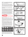
Some doors with windows have a decorative grille attached in
front of the window. The grille can be removed for cleaning or
painting purposes.
1)
2)
3)
Remove the tabs on the vertical legs of the grille (two on
short panel windows, six on long panel windows) from the
notches in the front window frame.
The grille can be firmly pulled out of the window.
Replacing the grille is the reversal of the process described
for removal. The two or six longer tabs on the vertical legs of
the grille must be placed in the notches under the lip of the
front window frame. The two shorter tabs on the horizontal
leg of the grille must be placed under the lip of the front
window frame.
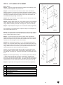
Glass Replacement
:$51,1*
To avoid injury, use extreme caution in handling glass window
pane. When the frame is removed, the exposed steel edge of the
door may be sharp. Avoid contact with the steel edges.
Glass Replacement: If your door is equipped with windows and
the glass should need replacement, follow the steps below:
1)
2)
3)
4)
5)
With someone holding the outside frame, remove the screws
from the inside window frame.
Pull the inside frame out of the door.
Carefully remove the broken or old glass.
Insert the new glass. The glass should be 17-5/8” x 14-1/16”
(short panel windows) or 40-1/8” x 14-1/16” (long panel
windows). See illustration below for glass dimensions of
single or double arched windows. (FIG. Glass-1)
With someone holding the outside frame, reinsert the screws
into the inside frame, trapping the glass.
Paint: Your steel garage door can be painted with a high quality,
100% acrylic latex (flat, satin, or semigloss) exterior grade paint.
Since all paints are not created equal, the following test needs to
be performed: paint should be applied on a small area of the
door (following the instructions on the paint container), allowed to
dry, and evaluated prior to painting the entire door. Paint defects
to look for are blistering and peeling. An additional test is to
apply a strip of masking tape over the painted area and peel
back, checking to see that the paint adheres to the door and not
to the tape.
After satisfactorily testing a paint, follow the directions on the
container and apply to the door. Be sure to allow adequate
drying time should you wish to apply a second coat.
Window frames & inserts can be painted with a high quality,
100% acrylic latex. The plastic should first be lightly sanded to
remove any surface gloss.
FIG. Glass-1
C35-R03-0410
Paint: YourYour
steelsteel
garage
door door
can be
painted
with a with
high aquality,
Painting:
garage
can
be painted
100%quality
acrylic100%
latex (flat,
satin,
or (flat,
semi-gloss)
exterior
grade paint.
high
acrylic
latex
satin, or
semigloss)
oil-basedgrade paint. Before painting the door it must be free
exterior
NOTE: Do not use oil-based paint. Using oil-based paint will
of
dirt,
caulk, waxes
mildew.
void
theoil,
warranty
on yourand
door.
Double Arch
Glass Dimensions
6WHHO'RRU/LPLWHG:DUUDQW\,QIRUPDWLRQ
Snap-In Grille Removal And Replacement:
Single Arch
Glass Dimensions
&ORSD\ /LPLWHG:DUUDQW\
Painting your Door
NOTE: Do not apply paint when door surface temperature is
different from manufacturer’s suggested temperature range for
application.
Table of Contents
Introduction and Opening Preparation
STEP 1 – Things to Know Before You Begin.................................................................................................... 3
STEP 2 – Read Safety Information .................................................................................................................. 4
STEP 3 – Check Headroom, Backroom, Sideroom.......................................................................................... 5
STEP 4 – Removing the Existing Door Springs ............................................................................................... 6
STEP 5 – Removing Door Sections and Track................................................................................................. 7
STEP 6 – Preparing the Opening ..................................................................................................................... 7
Preparing the New Door
Typical Garage Door Installation Illustration ..................................................................................................... 8
Hardware Components .................................................................................................................................... 9
Installing the New Door
STEP 7 – Preparing Bottom Section .............................................................................................................. 10
STEP 8 – Lift Handle Attachment............. ...................................................................................................... 12
STEP 9 – Installing Door Sections.............. ................................................................................................... 13
STEP 10 – Reinforcing the Top Section for Opener Attachment .................................................................... 14
STEP 11 – Assembling and Installing Track ................................................................................................... 15
STEP 12 – Lock Installation (if included).................. ...................................................................................... 17
STEP 13 – Pull Rope...................................................................................................................................... 17
STEP 14 – Spring Installation........................................................................................................................ .17
STEP 15 – Attaching an Automatic Opener.................................................................................................... 18
Maintenance/Adjustments/Options
Painting and Windows .................................................................................................................................... 19
Maintenance ................................................................................................................................................... 20
Checking and Adjusting the Door ................................................................................................................... 20
Replacement Parts ......................................................................................................................................... 20
STEP 1 – Things to Know Before You Begin
•
•
•
•
•
•
•
•
•
•
•
•
Read the instructions completely before starting the installation
of the door. Becoming familiar with the components before
assembling the door will reduce the installation time.
Be sure all hardware components for your new door are included
before removing existing door (see pages 8,9). If your door is
missing any parts, call the toll-free Consumer Services number
listed on the front of this manual.
Allow enough time to do the work; removing an existing door will
take approximately 1-3 hours.
An assistant may be required for lifting the unsprung door. It can
weigh from 100 to 500 pounds.
A typical installation takes between 9 and 12 hours to complete.
Keep in mind when planning the installation that the garage
will be open and unsecured when disassembling the old and
assembling the new door.
If the garage door is the only opening in the structure make sure
everything you need is inside. You will have no way of leaving the
garage until the track is assembled and installed. This will take
approximately 5 hours.
To avoid damage to the door, you must reinforce the top section
of the door in order to provide a strengthened mounting point for
attachment of an automatic opener (see page 14).
Low Headroom doors require special instructions. Options for
doors with low headroom can be found on page 5. Purchase
of additional hardware may be required. Check headroom
requirements in the chart on page 5 before beginning.
To avoid installation problems which could result in personal injury
or property damage, never reuse old track or hardware.
Doors installed in high windload regions (Florida and other high
wind prone areas) may require additional reinforcement beyond
what is detailed in these instructions. Please refer to supplemental
instructions for these areas.
Express warranties apply only to doors installed using original,
factory-supplied sections, parts, and hardware installed in strict
accordance with these instructions.
Tools Needed
•
“C” Clamps or Locking Pliers
•
Hammer
•
Screwdriver
•
Tape Measure
•
Level
•
Socket wrench kit
•
Pliers
•
Drill, 1/4", 3/16", & 3/8" drill bits, and 7/16" socket bit
•
Step ladder
•
Saw horses (with carpet or other soft material on top surface;
2 needed for doors up to and includiing 9'0" wide, 3 needed for
doors over 9'0" wide) or other supports for placing section on
while assembling
•
Hacksaw
•
Wood Saw
•
T-Square
•
Additional tools may be required; see the Spring Supplement for
more information.
Additional Material Required
•
Light household oil
•
1-1/4" x 1-1/4" Minimum punched angle
- 13 ga. (3/32") minimum thickness for Operator Reinforcement
(see page 14)
- 16 ga. (1/16") minimum thickness for rear track hangers on
doors weighing up to 300 lbs. that use torsion springs, or doors
weighing up to 150 lbs. that use extension springs. If your door
exceeds these weight limitations, or if you do not know the weight
of your door, 13 ga. angle should be used. (See page 16)
•
Eight 3/8" x 1" bolts and nuts for rear track hangers
•
Six 5/16" x 11/2" lag screws for rear track hangers
•
Ten 10d 3" nails
•
Stop Molding
•
Wood Block
•
Rope
G01-R03-0906
3
STEP 2 – READ THIS SAFETY INFORMATION
IMPORTANT!
To Protect Yourself From Injury You Must Carefully Read The Following Safety
Information and Warnings Before You Install Or Use Your New Garage Door
You can install your new garage door yourself IF…
•
a)
you have help (it may weigh up to 500 lbs.);
b)
you have the right tools and reasonable mechanical
aptitude or experience; and
c)
you follow these instructions very carefully.
Garage doors use springs to balance them. There are
two types of springs installed — extension or torsion.
Each of these is available in either a standard or EZ-SetTM
assembly option. Please look at the drawings on page 8 to
see which springs your old door has.
•
If your old door uses torsion springs, do not attempt
to remove the door or the springs yourself. Have a
qualified door repair service remove them. Attempting to
remove a torsion spring assembly without proper training
or tools may result in an uncontrolled release of spring
forces which can cause serious or fatal injury.
•
•
Only the track specified and supplied with the door
should be used.
•
The brackets at the bottom corners of your garage door
are under great tension. Do not attempt to loosen any
bracket fasteners except when and as directed in
detail in the following instructions. Otherwise, the
bracket could spring out with dangerous force.
•
Do not permit children to play beneath or with any
garage door or electric operating controls.
•
In removing a garage door that has extension springs,
follow the instructions carefully, including the use of “C”
clamps or locking pliers on both sides of the door in
order to keep the door from moving once the springs are
removed.
Keep hands and fingers clear of section joints, track, and
other door parts when the door is opening and closing to
avoid injury. The lift handles are located for safe operation
as well as easy use.
•
Bolts must be installed at the rear end of horizontal tracks.
These act to stop the rollers and keep the door from rolling
off the back of the track.
•
4
G01-R01-0704
•
Track installations must use sway braces on the rear track
hangers to prevent sideways movement. If the tracks are
not firmly stabilized they might spread, allowing the door
to fall and cause severe injury and damage.
•
Springs, cables, and bottom fixtures are under strong
spring tension. Do not attempt to loosen any fasteners
on these components. You could suddenly release
spring forces and risk severe injury.
•
If the garage door and/or any of the supporting track
are damaged, operating the door could be hazardous.
Call an authorized representative of the manufacturer or
professional door repair service promptly.
•
If repairs are ever required to your door, safety and
trouble-free operation can be best assured by using
original replacement parts.
•
Once you have completed the installation of your new
garage door, please be sure that your garage complies
with all applicable ventilation requirements before you
enclose any vehicles in the garage. Good ventilation
avoids fire and health hazards caused by fumes
accumulating within a well-sealed garage.
•
Clopay Building Products Company disclaims all liability
for any installation that is not in compliance with applicable
state or county building codes.
•
Doors equipped with automatic door operators can
cause serious injury or death if not properly adjusted and
operated. To ensure safety of these doors:
a)
test the sensitivity of the operator’s safety reverse
mechanism monthly;
b)
if your door has a pull down rope, you must remove
the pull down rope;
c)
make sure the door remains unlocked;
d)
do not allow children to play with the controls.
WARNING
In the interest of safety this symbol means WARNING or
CAUTION. Personal injury and/or property damage may
occur unless instructions are followed carefully.
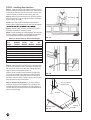
STEP 3 – Check Headroom/ Backroom/
Sideroom
Rough Opening = Door Size
Backroom = Door
Height Plus 18"
Headroom is the space needed above the top of the door for
the door, the overhead tracks, and the springs. Measure to
check that there are no obstructions in your garage within that
space. The normal headroom space requirement is shown in
Table 3-A. The backroom distance is measured from the back
of the door into the garage, and should be at least 18" more
than the height of the garage door. A minimum sideroom of
3-3/4" (5-1/2" for EZ-Set™ Extension Spring) should be
available on each side of the door on the interior wall surface
to allow for attachment of the vertical track assembly. The
rough opening should be the same size as the door. (FIG. 3-A)
Door
Height
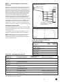
Track Radius: The radius of your track can be determined by
measuring the dimension “R” in FIG. 3-B. If dimension “R”
measures 11" to 12", then you have a 12" radius track. If “R”
equals 14" to 15", then you have a 15" radius track. (FIG. 3-B)
Headroom requirements
Headroom
Required
3-3/4" Minimum Side Room
(5-1/2" Minimum for EZ-Set™
Extension Spring)
FIG. 3-A
The standard headroom space requirement is shown in Table
3-A at right. (See page 8 if you have a question on which type
of spring you have.)
Low Headroom? If you have restricted headroom, several
remedies are available. See Table 3-B for various options.
NOTE: Installation of the various Low Headroom Options
differs from the installation of a standard headroom door.
Supplemental instructions are included with the hardware of
each Low Headroom Option.
R
FIG. 3-B
Table 3-A: Standard Headroom
Requirement Chart
Spring Type
Table 3-B: Low Headroom Options*
Track
Radius
Headroom
Required
12"
10"
15"
12"
12"
12"
15"
14"
EZ-Set™ Extension Spring or
Extension Spring
EZ-Set™ Extension Spring or
Extension Spring
EZ-Set™ Torsion Spring or
Torsion Spring
EZ-Set™ Torsion Spring or
Torsion Spring
Reduces Required
Headroom to:
Spring Type
Low Headroom Option
Extension and EZ-Set™
Extension
Extension and EZ-Set™
Extension
Extension and EZ-Set™
Extension
EZ-Set™ Torsion
Low Headroom Track
4-1/2"
Order Low Headroom Track.
Low Headroom Conversion Kit
(Modifies Standard Track)
Quick Turn Bracket
4-1/2"
Available at most retail stores.
EZ-Set™ Torsion
Torsion
Torsion
Low Headroom Track
(Front Mount Spring)
Low Headroom Conversion Kit
(Modifies Standard Track)
Low Headroom Track
(Front Mount Spring)
Low Headroom Track
(Rear Mount Spring)
8" on 12" Radius Track
How can I get this option?
Order Quick Turn Bracket Set.
9-1/2"
Order Low Headroom Track.
9-1/2"
Available at most retail stores.
9-1/2"
Available from and should be
installed by professional installer only.
Available from and should be
installed by professional installer only.
4-1/2”
*About 3" of additional headroom height at the center plus additional backroom is needed to install an automatic garage door
opener. Check door opener instructions.
G01-R02-0905
5
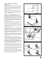
STEP 4 – Removing the Existing Door
Springs
WARNING
Garage doors use springs to balance the door weight. There
are two types of springs used — extension and torsion. Each
of these is available in either a standard or EZ-SetTM assembly
option. Please look at the drawings on page 8 to see which
springs your old door has installed. If your present door uses
standard torsion springs, do not attempt to remove the
door or the springs yourself. They should be removed by
a qualified door service professional. Attempting to remove a
torsion spring assembly without proper training and tools may
result in an uncontrolled release of spring forces which can
cause serious or fatal injury.
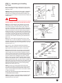
Removing EZ-SetTM Extension or Torsion
Springs
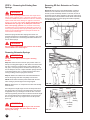
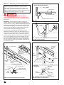
Step 4-1b: With the door in the DOWN position, position a
drill with a 7/16” socket bit over the worm drive. Using the
reverse (counter-clockwise) direction on the drill, remove all
the tension from the spring (repeat for each side). After spring
tension has been removed, detach the lift cables at both ends.
Disassemble and remove the springs and cable completely
from the door. (FIG. 4-C)
Extension springs and EZ-SetTM Springs are shown on a
sectional garage door in the illustration on page 8 to see which
springs your door has. The following instructions detail how to
remove these springs.
WARNING
“C” Clamp
FIG. 4-A
Serious injury could result if spring tension has not been
released before other work begins.
Removing Extension Springs
WARNING
Use two or more helpers to assist you in lowering
the door.
Step 4-1a: Raise the door to the full open position. Place “C”
clamps or locking pliers tightly on both sides of the track under
the door so the door is held securely in place. With the door
fully open, most spring tension has been removed. (FIG. 4-A)
Do not attempt to remove or adjust extension springs with door
in the down position. Use “C” clamps to keep the door from
moving or falling once the springs are removed.
Wood
Block
Step 4-2: Detach the cable at both ends. Disassemble and
remove the springs and cable completely from the door.
NOTE: Wood blocks should be placed underneath the door
when closing to prevent fingers from being trapped.
Step 4-3: Remove the “C” clamps from the track and carefully
close the door.
FIG. 4-B
Black
Housing
Some large doors might weigh as much as 500 pounds when
the spring tension is removed. The weight of the door will not
be apparent when you first begin to close the door. The door
will feel progressively heavier as it is lowered until its full weight
(as much as 500 pounds) is realized about one foot from the
floor. A single car door may weigh as much as 200 pounds.
(FIG. 4-B)
WARNING
To avoid injury, keep hands and fingers clear of section
joints, track, and other door parts while the door is
opening and closing.
6
G01-R01-0704
Worm
Drive
FIG. 4-C
Lifting
Cable
Sheave
Sheave
Fork
Safety
Cable
Red Mark
on Safety
Cable
Black
Bushing
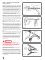
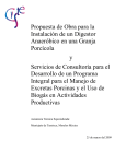
STEP 5 - Removing Door Sections & Track
Step 5-1: The door can now be disassembled. Starting with
the top section, remove the hardware and unstack the sections
one at a time. (FIG. 5-A)
Step 5-2: After all sections have been removed from the
opening, detach all remaining track and hardware from the
jambs. The hangers that attach the rear ends of the overhead
track to the ceiling (called rear track hangers) in many cases
can be reused on the new door if made of 13 gauge (3/32") or
heavier steel and is not loose or unstable. (FIG. 5-B)
WARNING
To avoid installation problems which could result in
personal injury or property damage, use only the track
specified and supplied with the door. Do not attempt to
reuse old track.
FIG. 5-A
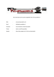
STEP 6 - Preparing the Opening
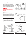
Step 6-1: On the inside of the garage your opening should
be framed with wood jambs, 2" x 6" if possible. The side
jambs should extend to approximately the same height as the
headroom required. If you have just removed an old door, the
jambs should be inspected for the condition of the wood. If the
wood is rotten, it should be replaced now. The jambs should
be plumb and the header should be level. If there are any
bolts fastening the jambs to the wall, the heads should be
flush so they don’t interfere with the installation of your new
door. (FIG. 6-A)
Rear Track
Hanger
NOTE: Rough opening (without stop molding) = Door size
Step 6-2: Door stop molding should be temporarily nailed to
the edges of the jambs flush with the inside. (FIG. 6-B)
Stop molding featuring a built-in weather seal is offered as
an option.
FIG. 5-B
Stop
Molding
2x6
“Header Jamb”
Opening
Height
2x6
“Side Jamb”
Opening
3-3/4" Minimum
Width
Side Room (5-1/2"
Minimum for EZ-Set TM
Inside of Garage
Extension Spring)
Looking Out
FIG. 6-A
Outside
8"
Minimum
Center
Post
(With
Two
Doors
Side By
Side)
Inside
FIG. 6-B
P08-R03-0510
7
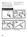
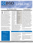
STEP 9 - Installing Door Sections
Door Installation Illustration
Step 9-1: Place the section in theTypical
opening soGarage
that it is against
the stop molding and Extension
centered from side
to side. Place
a level
Spring
System
on the section and use a piece of wood under one end or the
other (if necessary) to make the section level. (FIG. 9-A)
Shown on Complete Door
Trackat
Hanger
Step 9-2: Remove the level and drive a 3” nail inRear
the jambs
(Not
Included)
each end and bend it over the edge of the section to hold the
section in place. (FIG. 9-B)
Extension Spring
NOTE: These nails are all that will hold the stacked door
section in place until the tracks are secured to the back jambs.
Be sure the nails hold the sections firmly in position.
Step 9-3: With the Table 9-A below, determine the order in
which you will attach the remaining sections.
Section #4
NOTE: If a lock assembly was ordered with the door, the holes
for the lock may beTop
predrilled.
Bracket (Lock templates are included in
the lock instructions for doors without predrilled holes.)
Vertical Track
#3 Hinge
Table 9-A - Section Order for Various Door Heights
Section #3 2nd
1st
General
Safety
Door
(Bottom) Label(Lock)
3rd
4th
Height
Section
Section
#2 Hinge
6'0"
24"
24"
7'0"
21"Section #2 21"
7'3"
21"
21"
7'6"
24" #1 Hinge 21"
7'9"
24"
24"
Label 24"
8'0" Serial Number
24"
Section* Section
24"
21"
21"
21"
24"
21"
24"
21"
24"
24"
24"
Bottom safety
Bracket
* Section with general
label.
Inside Step Plate
Step 9-4: Place the next section face down on the saw horses.
If your door is predrilled for a lock, this section will be the one
with holes in the center of the panel face. Identify the bottom
Standard
Extension
Spring
edge as shown in
the illustration. (FIG.
9-C) System
Sheave
Attach a number 2 hinge to each end at the top edge using
#14 x 5/8" sheet metal screws. Remember that the number
is stamped on the side of the hinge that is to be attached to
the section. Attach a number 1 hinge to at each center stile
location along the top edge of the section.
Step 9-5: Keyed Lock Installation.
If you
wish to install a
Stationary
Sheave
keyed lock, begin the lock installation now according to the
supplemental instructions included with the lock hardware. If
your door did not come with a keyed lock, install lift handle as
shown on previous page.
EZ-Set™ Extension Spring System
Sheave
Stop Molding
Containment Cable
Stationary Sheave
Sheave
Door Jamb
Flag Bracket
Top Bracket
Vertical Track
Operator
FIG. 9-A
Label
#3 Hinge
#1 Hinge
Long Track Bracket
#1 Hinge
#2 Hinge
#1 Hinge
#1 Hinge
Short Track Bracket
Bottom Bracket
Standard Torsion Spring System
End Bearing Plates
Center Bearing Plate
Torsion Tube
FIG. 9-B
Stationar y
Red Winding
Cone
Cone
Center Stile
Black Winding
Left (Red)
Cone
Right (Black)
Cable Drum
Cable Drum
Bottom
Edge
EZ-Set™
Torsion Spring System
EZ-Set™
Winding Unit
End
Stile
#1 Hinge
#2 Hinge
Left Cable Drum
EZ-Set™ Winding Unit
EZ-Set™ Bracket
3
FIG. 9-C
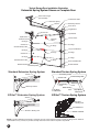
NOTE: The above illustration represents a composite of many of the features found on a variety of garage doors. While not
representative of any one door, it provides a handy reference for the location of specific components
12
8
P03-R01-0704
P01-R01-0704
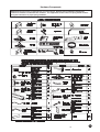
Hardware Components
NOTE: All doors will receive (1) spring kit and (1) or more springs. Separate spring installation supplemental
instructions should be included with door hardware. This supplement contains a list of all spring related hardware
along with instructions on proper spring installation.
P03-R01-0704
P01-R01-0704
P08-R01-0704
9
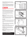
STEP 7 - Preparing Bottom Door Section
Step 7-1: Spread the hardware on the garage floor in groups
so that you can easily find the parts.
Step 7-2: Find the section with the aluminum weatherstrip
retainer fastened to one edge. The aluminum weatherstrip
retainer is on the bottom edge of the bottom section. Place the
section on saw horses face down. (FIG. 7-A) Be sure to cover
saw horses with carpet or cloth so as not to scratch section.
FIG. 7-A
Aluminum Weatherstrip Retainer
Step 7-3: Bend and break apart bottom brackets by hand
along end tabs as shown. (FIG. 7-B) Be sure to remove
connecting tab.
Step 7-4: Insert safety tabs on bottom bracket into slots on end
stile of door. Slide bottom bracket up to fully engage tabs. (FIG.
7-C) Attach all hardware with #14 x 5/8” sheet metal screws.
Attach the bottom brackets with two screws to the bottom
corners of the section. Screws go into the end stiles. Hook
the looped ends of the steel lift cable over the buttons on the
bottom brackets. (If your door came with standard extension
springs, the lift cables are the longer and smaller diameter
of the two sets of cable. If your door came with EZ-Set™
Extension Springs, do NOT attach lift cables at this time! Do
NOT use the shorter safety containment cables as lift cables,
as this can cause improper door function). (FIG. 7-D)
WARNING
FIG. 7-B
#14 x 5/8" Sheet Metal Screws
Bottom Section
Slots
FIG. 7-C
Bottom
Bracket
Safety Tabs
Weatherstrip
Failure to properly engage safety tabs on bottom bracket
into slots on edge of door can result in severe injury when
spring tension is applied.
Step 7-5: Hinges are identified by number 1, 2, 3 (and
sometimes 4, on 5 section doors only). This number is
stamped on the hinge. Attach a number 1 hinge to each pair of
pre-punched holes along the top edge of the section using #14
x 5/8” sheet metal screws. The number is stamped on the side
of the hinge that is to be attached to the section. (FIG. 7-E)
NOTE: Determine if your door thickness is 1-3/8” or 2” and
determine the width of the endstile (FIG. 7-E). If Table 7A below shows a need for a reinforcing strut on the bottom
section, it should be attached overlapping the hinges. Use
1/4” x 3/4” self tapping screws to attach strut as shown in
the illustration. When pre-drilled holes in strut do not line up
vertically with hinge locations, you will be required to drill (2)
3/16” pilot holes through the strut, hinge, and door at each
hinge location, or use a drill or impact wrench with a 7/16”
socket to drive self-tapping screws through strut, hinge, and
door. (FIG. 7-F)
Table 7- A - Sections Requiring Struts
Door
Door End Stile Section
Thickness Width
Width
Bttm
3rd*
Top
All
Up to 15' All
-
-
1-3/8"
15'2"-16' 2-1/2"
-
-
4
1-3/8"
16'2"-18' 2-1/2"
4
4
4
2"
15'2"-18' 2-1/2"
-
-
4
2"
15'2"-16' 3"
-
-
2"
18'2"- 20' 3"
-
-
4
*Section with general safety label.
NOTE: Doors installed in high windload regions (Florida
and other high wind prone areas) may require additional
reinforcement beyond what is detailed in these instructions.
Please refer to supplemental windload instructions for these
areas.
10
P01-R01-0704
FIG. 7-D
#1 Hinge
#14 x 5/8"
Sheet Metal Screws
End Stile
Width
Bottom
Astragal
Door
Thickness
FIG. 7-E
1/4" x 3/4" Self
Tapping
Screws
Strut
End Hinge
FIG. 7-F
End Stile
STEP
8 – 8LIFT
ATTACHMENT
STEP
- LiftHANDLE
Handle Attachment
Lift Handle Preparation
Bottom Section
StepIf8-1:
supplemental
provided
you Using
have athe
2” thick
door, no templates
modifications
to the in
liftthe handle bag, determinehandle
the handle
configuration
for your
size.thick door, cut
are necessary.
If you
havedoor
a 1-3/8”
the stems on the lift handle along the ridge line using a
Stephacksaw
8-2: From
the8-A).
front of the door section, find the center of the distance
(Fig.
between embosses. According to the template provided in the bottom handle
Bottom
Section
packaging
(FIG
T1) line up the center lines and the bottom section. Drill two 1/2”
holesFrom
where
indicated
the frontdrill
skin(2)
of 1/2"
the section
and insulation, but
the front sidethrough
of the section,
holes through
STOP
BEFORE
drilling
through
the
back
skin.
the section according to the Bottom Section Hole Pattern (FIG.
8-C). A T-Square should be used to ensure that they are
Stepvertically
8-3: Flipinover
section.
theoutside
back ofkeyed
the door
line.the
If your
doorFrom
has an
lock,drill
thetwo 5/16” holes,
through
the
back
skin.
(FIG
T2)
hole pattern should be drilled on the bottom section directly
below the lock. If your door does not have an outside keyed
Steplock,
8-4: the
Slide
thepattern
black headed
1/4”
carriage
boltbelow
through
horizontal spade
hole
should be
drilled
directly
thethe
hinge
handle,
the
handle
spacer,
the
front
of
the
section,
the
back
of
the
section, the
closest to the horizontal center of the door. Install the lift handle
roll grip
handle,
and
finally
secure
with
1/4”
flange
nuts.
(FIG
8-A
or
& inside step plate assembly using (2) #14 x 5/8" sheet metal FIG 8-B)
screws (Fig. 8-B).
Step 8-5: Repeat Step 8-2 through 8-4 for second bottom handle (if applicable).
IMPORTANT: Use a wrench or a socket to drive screws.
Second
Section
be installed
at the
Stepor9-4.
Not Required on
Do not
over(to
tighten.
Do not
usecompletion
an electricofdrill
driver.
FIG. 8-B
Doors with Outside Keyed Lock)
2nd Section (to be installed at the completion of Step 9-4.
STEP 8 – LIFT HANDLE ATTACHMENT
on Doors
with Outside
Keyed
StepNot
8-6:Required
On the back
of the provided
template
findLock)
your door handle configura-
FIG 8-A
tion.
Use
the
is on
the other
to drill
thethrough
holes in your second
Bottom
Section
From
the template
front sidethat
of the
section,
drill side
(2) 1/2"
holes
Step 8-1: itUsing
the
supplemental
templates
provided
in the handle bag, determine the handle configuration for your door size.
section,
will
be
either
FIG
T3
or
FIG
T4.
the section according to the 2nd Section Hole Pattern (FIG.
Step8-C).
8-2: From
the front of the
door section,
find the
of thethat
distance
between
A T-Square
should
be used
tocenter
ensure
they
are embosses. According to the template provided in
Step
8-7:handle
From
the front
the
door
thebottom
center
of the
distance
the bottom
(FIGof
T1)
line
up thesection,
center
linesfind
anddrilled
the
section.
Drill
two 1/2” holes where indicated through
vertically
inpackaging
line.
The
hole
pattern
should
be
directly
the front skin
of the sectionand
and the
insulation,
but STOP
BEFORE
drilling
through
the back skin.
between
embosses
middle
of
the
section
height.
According
to the temabove the hinge closest to the horizontal center of the door.
plate found in Step 8-6 line up the vertical and horizontal center lines. Drill the
Step 8-3: Flip over the section. From the back of the door drill two 5/16” holes, through the back skin. (FIG T2)
indicated
1/2” Lift
holes
through the section and insulation.
Painting
Handles
Step 8-4: Slide the black headed 1/4” carriage bolt through the horizontal spade handle, the handle spacer, the front of the section, the
Lift outside
Handles
can
be
painted
using
a 1/4”
quality
onhandle
or or FIG
backPlastic
of
the (Two
section,
the roll grip
handle,
and
finally secure
flangespray
nuts.
(FIG
8-A
8-B)to
Step
8-8
spade
handles):
Forwith
one
outside
spade
skip
brushed
on
enamel
paint.
Step
8-9.
For
two
outside
spade
handles,
attach
the
handle
backer
plate
to the
Step 8-5: Repeat Step 8-2 through 8-4 for second bottom handle (if applicable).
back of the door with two #14 x 5/8” sheet metal screws going through the inside
Second
(to and
be installed
at the
completion
Step 9-4.
NotMake
Required
on Doors
with Outside
roll
gripSection
handle
into the
inside
skin.of(FIG
8-A)
sure
the holes
in theKeyed Lock)
handle
backer plate line up with the drilled holes in Step 8-7.
Step 8-6: On the back of the provided template find your door handle configuration. Use the template that is on the other side to drill
the holes in your second section, it will be either FIG T3 or FIG T4.
Slide two 1/4” black headed carriage bolts through the vertical spade handle,
Step 8-7: From the front of the door section, find the center of the distance between embosses and the middle of the section height.
the
handle spacers, the door section, and through the backer plate. Secure on
According to the template found in Step 8-6 line up the vertical and horizontal center lines. Drill the indicated 1/2” holes through the
the
inside
with 1/4” flange nuts. Do this for each handle. (FIG 8-A) Skip to Step
section
and insulation.
8-10.
Step 8-8 (Two outside spade handles): For one outside spade handle skip to Step 8-9. For two outside spade handles, attach the
handle backer plate to the back of the door with two #14 x 5/8” sheet metal screws going through the inside roll grip handle and into
Step
8-9skin.
(One
outside
spade
handle):
For
onebacker
outside
spade
handle,
slide
the inside
(FIG
8-A) Make
sure the
holes in the
handle
plate line
up with
the drilled
holestwo
in Step 8-7.
¼” black headed carriage bolts through the vertical handle, handle spacers,
Slide section,
two 1/4” black
carriage
bolts
throughplate.
the vertical
spade
the handle
door go
section, and through the
door
andheaded
through
the
backer
The
tophandle,
carriage
bolt spacers,
shouldthealso
backer plate. Secure on the inside with 1/4” flange nuts. Do this for each handle. (FIG 8-A) Skip to Step 8-10.
through the top hole of the roll grip handle. The bottom of the roll grip handle is
attached
with
a #14
x 5/8”
sheet
screw
theslide
backer
(FIGcarriage
8-B) bolts through the vertical
Step 8-9 (One
outside
spade
handle):
Formetal
one outside
spadeinto
handle,
two ¼”plate.
black headed
handle, handle spacers, door section, and through the backer plate. The top carriage bolt should also go through the top hole of the roll
grip handle. The bottom of the roll grip handle is attached with a #14 x 5/8” sheet metal screw into the backer plate. (FIG 8-B)
Step
8-10: Repeat Step 8-7 through 8-9 for second handle set (if applicable).
FIG 8-B
Step 8-10: Repeat Step 8-7 through 8-9 for second handle set (if applicable).
Item
No.
1
2
3
4
5
6
7
8
Description
Black Vertical Spade Handle
Black Horizontal Spade Handle
1/2” OD Handle Spacer
1/4” Black Head Carriage Bolt
1/4” Flange Nut
Roll Grip Handle
#14 x 5/8” Sheet Metal Screw
Handle Backer Plate
P08-R01-0704
11
STEP 9 - Installing Door Sections
Step 9-1:: Place the section in the opening so that it is against
the stop molding and centered from side to side. Place a level
on the section and use a piece of wood under one end or the
other (if necessary) to make the section level. (FIG. 9-A)
Step 9-2:: Remove the level and drive a 3” nail in the jambs at
each end and bend it over the edge of the section to hold the
section in place. (FIG. 9-B)
Stop Molding
NOTE: These nails are all that will hold the stacked door
section in place until the tracks are secured to the back jambs.
s.
Step 9-3: With the Table 9-A below, determine the order in
which you will attach the remaining sections.
NOTE:: If a lock assembly was ordered with the door, the holes
for the lock may be predrilled. (Lock templates are included in
n
the lock instructions for doors without predrilled holes.)
Table 9-A - Section Order for Various Door Heights
1st
2nd
Door
(Bottom) (Lock)
3rd
Height
Section Section Section*
6'0"
24"
24"
24"
6'3"
18"
18"
18"
6'6"
21"
18"
18"
6'9"
21"
21"
18"
7'0"
21"
21"
21"
7'3"
21"
21"
21"
7'6"
24"
21"
21"
7'9"
24"
24"
21"
8'0"
24"
24"
24"
* Section with general safety label.
FIG. 9-A
4th
Section
21"
21"
21"
21"
24"
24"
24"
24"
Step 9-4: Place the next section face down on the saw horses.
If your door is predrilled for a lock, this section will be the one
with holes in the center of the panel face. Identify the bottom
edge as shown in the illustration. (FIG. 9-C)
Attach a number 2 hinge to each end at the top edge using
#14 x 5/8" sheet metal screws. Remember that the number
is stamped on the side of the hinge that is to be attached to
the section. Attach a number 1 hinge to all other pre-punched
holes along the top edge of the section.
FIG. 9-B
#14 x 5/8" Sheet
Metal Screws
Step 9-5: Keyed Lock Installation. If you wish to install a
keyed lock, begin the lock installation now according to the
supplemental instructions included with the lock hardware. If
your door did not come with a keyed lock, install lift handle as
shown on previous page.
#1 Hinge
Bottom Edge
FIG. 9-C
12
P01-R01-0704
#2 Hinge
End Stile
STEP 9 - Installing Door Sections
(Continued)
Step 9-6: Place the second section on top of the first section.
Drive a 3" nail in the jambs at each end and bend it over the
edges of the section to hold the section in place. Attach the
hinges from the top of the first section to the bottom of the
second. (FIG. 9-D)
Step 9-7: Place the third section on saw horses. Attach #3
hinges to the ends at the top edge and #1 hinges to each pair
of pre-punched holes along the top edge using #14 x 5/8"
sheet metal screws. (FIG. 9-E)
Safety
Label
FIG. 9-D
NOTE: If your door was supplied with more than 1 strut
(consult Table 7-A on bottom of page 10), use 1/4” x 3/4"
self tapping screws to attach strut as shown in FIG. 7-F on
page 10. When pre-drilled holes in strut do not line up vertically
with hinge locations, you will be required to drill (2) 3/16” pilot
holes through the strut, hinge, and back skin of door at each
hinge location, or use a drill or impact wrench with a 7/16”
socket to drive self-tapping screws through strut and hinge and
into door. (FIG. 9-E)
#14 x 5/8" Sheet
Metal Screws
#1 Hinge
Step 9-8: Place the third section on top of the other sections
and nail in place as before. Attach the hinges from the top of
the previous section to the bottom of this section. (FIG. 9-D)
If you have two sections left, repeat Steps 9-7 and 9-8 using
#4 hinges on the end of the top edge and #1 hinges to all other
stiles along the top edge.
Step 9-9: Place the last section on the saw horses. Attach the
top roller brackets as shown. The top roller brackets are to be
attached with three #14 x 5/8” sheet metal screws. The top of
the bracket goes into the bottom hinge hole.The bottom of the
bracket goes in smaller holes, either 6-1/4” or 8” (depending on
door model) from the top of section. (FIG. 9-F)
#3 Hinge
FIG. 9-E
Bottom Edge
#14 x 5/8"
Sheet Metal
Screws
1/4" x 3/4"
Self Tapping
Screws
(2) 1/4" Washers
NOTE: 8’ and 10’ wide doors with 3” end stiles and windows in
the top section require the addition of (2) 1/4” washers on the
bottom of each top bracket before installation of screws. (See
inset in FIG. 9-F)
If your door was supplied with any struts (consult Table 7-A
on bottom of page 10), use 1/4” x 3/4” self tapping screws to
attach strut as shown in the illustration. When pre-drilled holes
in strut do not line up vertically with hinge hole locations, you
will be required to drill (2) 3/16” pilot holes through the strut
and the back skin of door at each hinge hole location, or use a
drill or impact wrench with a 7/16” socket to drive self-tapping
screws through strut and into door. (FIG. 9-F)
End Stile
Strut (If Required)
End Stile
FIG. 9-F
Bottom Bracket
Top Bracket
#1 Hinge
Step 9-10: Place the top section on top of the other sections
and nail in place as before. Attach the hinges from the top of
the previous section to the bottom of this section. (FIG. 9-D)
NOTE: If your door is to be used with an electric operator, you
must reinforce the top section before placing it in the opening.
Proceed to step 10 prior to completing this step.
Step 9-11: Place a roller in the top and bottom brackets and
in the tubes in each of the hinges at the ends of each section.
Some hinges have two tubes. Place the roller in the tube that is
farthest from the face of the door. (FIG 9-G)
#2, 3, or 4 Hinge
Top Bracket
FIG. 9-G
P08-R01-0704
13
STEP 10 - Reinforcing the Top Section
for Opener
To avoid damage to your door, you must reinforce the top
section of the door in order to provide a mounting point for
the opener to be attached. You will need one (1) or three (3)
pieces of 1-1/4" x 1-1/4" minimum punched angle at least
13 gauge or 3/32" thick from your local hardware or building
supply store. Figures 10-A to 10-D show how punched angle
is to be affixed to door. Angle iron may need to be trimmed
depending on door section height and distance between center
stiles.
NOTE: An opener bracket kit specifically designed for
opener attachment may be included or may be purchased as
an option (silver galvanized or white powder coated).
Instructions are provided with the kit.
NOTE: Operator may be attached up to 2 feet off center.
(Doors with Torsion Springs Only)
Do NOT install the bracket supplied with the opener.
Failure to reinforce the door, as illustrated, will void
your warranty.
15'0'' up to 15'10'' &
19'0'' up to 20'0'' Wide Doors
with Strut
5''
8'0'' up to 9'0'' Wide Doors
Vertical Punched Angle
18" or 21" Long
Notch Cut
on Vertical Angle
Punched Angle for
Operator Draw Bar
Attachment
Strut
18'' or 21''
Punched Angle Two 18'' or 21'' pieces
(measure top section height).
FIG. 10-B
FIG. 10-A
Required materials:
(2) 18” or 21” lengths of angle iron, (2) ¼’’x1’’ bolts,
(2) ¼’’ lock washers, (2) ¼’’ nuts, (4) #14 x 5/8" sheet metal
screws, and (4) 1/4" x 3/4" self tapping screws.
Required materials:
(1) 18" or 21" length of angle iron, and
(4) #14 x 5/8" sheet metal screws.
2''
10'0'' up to 14'10'' Wide Doors
27'' or 50''
18'' or 21''
Notch Cut
on Vertical Angle
5''
Notch Cut
on Vertical Angle
Punched Angle
for Operator Draw
Bar Attachment
Strut
18'' or 21''
Punched Angle One 27'' long piece
(12' wide doors require one 50'' long piece) and
FIG. 10-C two 18'' or 21'' pieces (measure top section height).
Required materials:
(2) 18” or 21” and (1) 27” or 50” length of angle iron
(2) ¼’’x1’’ bolts, (2) ¼’’ lock washers, (2) ¼’’ nuts,
(8) #14 x 5/8" sheet metal screws.
14
P01-R01-0704
16'0'' up to 18'0'' Wide
Doors with Strut
18'' or 21''
FIG. 10-D
Required Materials:
(1) 18" or 21" length of angle iron,
(2) #14 x 5/8" sheet metal screws,
and (2) 1/4" x 3/4" self tapping screws.
STEP 11 – Assembling and Installing
the Track
Before assembling brackets to vertical track be sure to read
Step 11-1 and Step 11-2. Refer to illustration for placement of
brackets on track.
NOTE: Brackets may already be riveted in place. If additional
adjustment is required, the rivets can be drilled out and the
brackets can be reattached with track bolts and flange nuts
(available through the toll-free Consumer Services number, see
outside cover).
WARNING
1/4" x 5/8"
Track Bolt
Step 11-2: Loosely attach the flag bracket to the top of the
track with two 1/4" x 5/8" track bolts and 1/4" flange nuts with
the head of the bolts in the track. Make sure bolts and nuts are
attached through the proper holes in flag bracket for your door
thickness. (FIG. 11-C)
1-3/8" & 1-1/2"
Thick Door
Use These
Two Holes
1/4" Flange
Nut
2" Thick Door
Use These
Two Holes
Flag Bracket
FIG. 11-B
1/4" x 5/8"
Track Bolt
Flag Bracket
Top
Left Hand
Vertical Track
Assembly
(Refer to FIG. 11-B to determine proper bolt placement.)
NOTE: If additional adjustment is required, horizontal slots in
flag brackets can be used for attachment to vertical track.
Step 11-3: Place the track over the rollers on the door. Move
the track close to the door so that the rollers are all the way
into the hinges. Do not force the track too tightly or the door
will bind. This should leave about 1/2" between the edge of the
door and the track. Pilot holes of 3/16" are required at each
lag screw location before installing the lag screw. Lift track
about 1/2" from the floor and fasten the flag bracket and track
brackets to the jamb with 5/16" x 1-5/8" lag screws. The flag
bracket requires three screws, one each in the top, middle, and
bottom holes. Do this for both sides of the door. When the track
brackets and flag brackets are securely fastened to the jamb,
tighten the track bolts and flange nuts connecting the flag
brackets to the tracks. (FIG. 11-D)
Top View
Left Side
Note: Use One
Track Bolt In Slot.
FIG. 11-A
To avoid installation problems that could result in injury or
property damage, use only track provided with new door.
Step 11-1: Loosely fasten the track brackets to the vertical
track using one 1/4" x 5/8" track bolt and 1/4" flange nut as
shown with the head of the bolt inside the track. There are
two sizes of brackets for 7’ high doors, and three sizes for 8’
high doors. The shortest track brackets should be installed ten
inches from the bottom of the track with the flange facing the
flat side of the track, one on the left and one on the right. The
next larger sized pair of brackets should be installed centered
on the track. If you have an 8’ high door, the remaining pair
of brackets should be installed ten inches from the top of the
vertical track. The flat side of the track goes toward the wall.
(FIG. 11-A)
Wall
Side
1/4" Flange
Nut
FIG. 11-C
Bottom
Shorter
Track
Bracket
Right Hand
Vertical
Track
Longer Assembly
Track
Bracket
Finished Track Assembly
NOTE: The tops of the vertical tracks must be level with
each other. Check this by measuring from the top of the door
sections to the top of the track on both sides. If they are not
equal, cut some material off the bottom of one track to lower it
or raise the other track.
Do not raise the vertical track beyond the bottom rollers
on the bottom section of door.
NOTE: Do not attach any brackets directly to drywall. All track
brackets, flag brackets, and spring brackets should only be
attached directly to wood bucks.
FIG. 11-D
G01-R02-0905
15
STEP 11 - Assembling and Installing the
Track (Continued)
NOTE: Pressure-treated lumber purchased after January 2004 is
treated with chemicals that have highly corrosive effects on metal
fasteners. The fasteners provided with your door are intended for
use with standard lumber (not pressure-treated) only. If you are
installing your door into an opening framed with pressure-treated
lumber purchased after January 2004, two items must be changed:
1) 5/16” x 1-5/8” lag screws with a minimum galvanization
equivalent to G185 must be purchased for this application, and
2) to prevent potential corrosion between lumber and track/spring
components, paint either the surface of the pressure-treated
lumber or those surfaces of the track and spring components that
come in contact with the pressure-treated lumber.
Horizontal Angle
Horizontal Track
FIG. 11-E
Step 11- 4: Fasten the horizontal angle to the horizontal (curved)
track with two 1/4" x 5/8" track bolts and 1/4" flange nuts so that the
heads of the track bolts are on the inside of the track. On some
doors this angle may be 82" long and will require three additional
fasteners per side. If the angle has been preassembled, skip Step
11-4 and proceed with Step 11-5. (FIG. 11-E)
Rope
Flag Bracket
Horizontal Angle Bracket
Step 11- 5: Temporarily support the rear end of the track with a
rope from the trusses overhead in the garage or on a tall ladder.
(FIG. 11-F)
Step 11-6: Place the track over the roller in the top bracket. Attach
the curved end of the horizontal track to the flag bracket with two
1/4" x 5/8" track bolts and 1/4" flange nuts so that the heads of the
screws are on the inside of the track. The horizontal and vertical
track must join together to form a continuous channel for the
rollers. Attach the end of the horizontal angle to the top of the flag
bracket with a 3/8” x 3/4” carriage bolt and 3/8” hex nut. Use the
top set of slots for 15” radius track, the middle set of slots for 12”
radius track, and the bottom set of slots for Low Headroom track.
(FIG. 11-G)
Step 11-7: Rear track hangers need to be made at this time. Use
1-1/4" x 1-1/4" punched angle, 13 gauge or 3/32" steel. These are
not provided with the standard hardware. They are used to attach
the rear of the horizontal track to the ceiling joist.
Horizontal
Track
Vertical
Track
FIG. 11-F
3/8" x 3/4"
Carriage
Bolt
Enough angle iron or punched angle should be purchased to make
two rear track hangers. These hangers must be strong enough
to hold the full weight of the door. Attach a bolt at least 1" long
through the end of each track to stop the door at the end of its
travel. (FIG. 11-H)
WARNING
Horizontal
Angle
Horizontal
Track
FIG. 11-G
Sway braces must be used to prevent tracks from
spreading and allowing door to fall, which could cause
serious injury. Bolts placed in the end of each track
(FIG. 11-H) must be at least 1" long to prevent the top
section from exiting the track.
NOTE: Rear track hangers should not be mounted any farther
than 6" from the end of horizontal track.
Step 11- 8: Placement of rear track hangers is critical for the
door to operate properly. The rear track hangers should hold the
horizontal track level and square to the door. Squareness should
be measured by comparing two diagonal distances: 1) the distance
from the top left-hand corner of the door to the rear of the righthand horizontal track and 2) the distance from the top right-hand
corner of the door to the rear of the left-hand horizontal track. (FIG.
11-I, opposite page)
16
G01-R01-0704
3/8" x 1"
Bolts & Nuts
(4 places)
Sway Brace
Bolt Blocks
Door Travel
FIG. 11-H
Step 11- 8, Continued: Adjust the position of the tracks if
the squareness distances are not within 1/2" of each other.
Horizontal track can be out of level up to 1" from front jamb to
rear track hanger. (FIG. 11-I)
When the track is square and level with the opening, the track
hangers can be fastened permanently to the ceiling trusses.
Three 5/16" x 1-1/2" lag screws are recommended. Be sure
3/16" pilot holes are drilled before installing 5/16" lag screws.
The attachment must be strong enough to hold the weight of
the door.
WARNING
Use adequate length screws to fasten rear track hangers
into trusses. Door may fall and cause serious injury if not
properly secured.
FIG. 11-I
Step 11- 9: With the track installed, the top door section can
now be properly adjusted. With the slide on the top bracket
loose, force the top of the door against the stop molding or
door jamb. Pull the roller towards you so it is tight against the
groove in the track and tighten the slide bolts. (FIG. 11-J)
Slide
Bolts
At this time, remove the 3" nails that were used to hold
sections in place prior to installation of the track assembly.
(Refer back to FIG. 9-B.)
STEP 12 – Lock Installation (If Included)
Keyed Lock:
If your door has an exterior keyed lock, please complete the
installation of the lock at this time following the instructions
provided with your lock hardware. If your door has a slide bolt
lock, install according to the instructions below.
Slide Bolt:
Slide
Top Roller
Bracket
FIG. 11-J
#14 x 5/8" Sheet Metal Screw or 1/4" x 1" Lag Screw
The inside slide bolt is installed on the end stile of the second
section using (4) #14 x 5/8" hex head sheet metal screws (steel
doors) or (4) 1/4" x 1" lag screws (wood doors). (FIG. 12-A)
NOTE: 3/16" holes may have to be predrilled before installing
screws.
The slide bolt rests against the top of one of the rectangular
engaging slots in the vertical track. Proper alignment is easier
to achieve by using track as a guide.
NOTE: It may be necessary to knock out the slug in the vertical
track to open the slot for lock engagement. Remove slug by
striking with a hammer from the outside of the track.
FIG. 12-A
IMPORTANT: If your door is going to be equipped with an
automatic garage door opener, make sure that the door is
always unlocked when the opener is being used. This will
avoid damage to the door.
STEP 13 – Pull Rope (Manually Operated
Doors Only)
To complete the door section installation, tie the pull rope
provided to the bottom roller shaft. (FIG. 13-A)
STEP 14 – Spring Installation
It is now time to install the spring. Proceed to springing
instructions that came with your spring hardware.
Pull Rope
FIG. 13-A
G01-R02-0905
17
STEP 15 – Attaching an Automatic Opener
IMPORTANT: To avoid damage to your door, you must
reinforce the top section of the door in order to provide a
mounting point for the opener to be attached. Refer to the
section of this manual titled Reinforcing the Top Section on
page 14 for specific instructions. Failure to reinforce the door
as illustrated will void the warranty on your door.
Opener Rail Mounting Distance
Ceiling
Opener Rail
WARNING
Horizontal Track
To avoid risk of strangulation or personal injury to
children, if your door has a pull rope, you must remove
the pull down rope when you install an automatic garage
door opener.
IMPORTANT: When installing an automatic garage door
operator, make sure to follow manufacturer’s installation and
safety instructions carefully. Remove the pull down rope and
unlock or remove the lock. If attaching an operator bracket
to the wooden anchor pad, make sure the wood anchor pad
is free of cracks and splits and is firmly attached to the wall.
Always drill pilot holes before attaching lag screws.
The operator arm will usually be attached to the vertical
reinforcement member at roughly the same height as the top
roller of the door. Attach the opener arm to the reinforcement
as shown in Figures 15-B to 15-D. To prevent the top of the
door from bending, the opener rail should be mounted no less
than 2" and no greater than 5" from the face of the door with
the door in the open position (FIG. 15-A). Additionally, when
the door is closed, the portion of the operator arm attached to
the door should be at angle of approximately 60 degrees from
the vertical (FIG. 15-B).
Keep Clearance at 2"–5"
FIG. 15-A
Clevis
Pin
60°
FIG. 15-B (Doors with supplied Reinforcement Bracket
and Stile in Center of Door)
Opener Arm Attachment To Horizontal Angle Or Strut
Opener Arm Attachment To Vertical Angle
Opener Arm
Horizontal
Punched
Angle
Supplemental
Bracket (Not Available
On All Doors)
3/8" x
1-1/2"
Hex Bolt
3/8"
Hex Nut
Punched
Angle
Horizontal Angle
Or Strut
Opener Arm
Front View (Assembled)
Punched
Angle
Opener Arm
Top View
(assembled)
Mounting
Surface Of
Door
Lock These Nuts
Together Securely
Horizontal
Angle
Or Strut
Vertical Punched
Angle
Leave
Clearance
Opener
Arm
FIG. 15-C (Doors with odd number of Panels)
18
G01-R01-0704
Vertical
Punched
Angle
Lock These
Nuts Together
Securely
FIG. 15-D (Doors with Angle Iron Reinforcement
Bracket and Stile in Center of Door)
:HZLOOUHSDLURUUHSODFHDWRXURSWLRQDQ\JDUDJHGRRUVHFWLRQRUKDUGZDUHWKDWLVGHIHFWLYHLQPDWHULDORUZRUNPDQVKLSSXUVXDQWWRWKHWHUPV
RIWKLVOLPLWHGZDUUDQW\7KLVZDUUDQW\H[WHQGVWRDQGEHQH¿WVRQO\WKHRULJLQDOSXUFKDVHURIWKHJDUDJHGRRU7KLVZDUUDQW\GRHVQRWDSSO\WR
FRPPHUFLDOLQGXVWULDORUDQ\RWKHUQRQUHVLGHQWLDOLQVWDOODWLRQ
:H ZLOO SURYLGH DW QR FRVW WR \RX VHFWLRQVVHFWLRQ FRPSRQHQWV KDUGZDUH VSULQJVVSULQJ FRPSRQHQWV RU ZLQGRZV WR UHSDLU RU UHSODFH
GHIHFWLYHVHFWLRQVKDUGZDUHVSULQJVVSULQJFRPSRQHQWVRUZLQGRZV$OOODERUFRVWVDVVRFLDWHGZLWKWKHUHPRYDODQGUHLQVWDOODWLRQRIDQ\
UHSDLUHGVHFWLRQVHFWLRQFRPSRQHQWVKDUGZDUHRUVSULQJVSULQJFRPSRQHQWVDQGWKHLQVWDOODWLRQRIUHSODFHPHQWVHFWLRQVVHFWLRQFRPSRQHQWV
KDUGZDUHVSULQJVSULQJFRPSRQHQWVRUZLQGRZVZLOOEH\RXUUHVSRQVLELOLW\:HUHVHUYHWKHULJKWWRLQVSHFWDQGRUYHULI\DQ\FODLPHGGHIHFW
7KHDSSOLFDEOHOLPLWHGZDUUDQW\SHULRGVDUHDVIROORZV
0RGHO
3DLQW6\VWHP
GD2SP, GD2LP, GD1SP, GD1LP, /LPLWHG/LIHWLPH
GD1SU, GD1LU,
GD2SU, GD2LU
GR2SP,
GR2LP,
GR1SP,
GR1LP,
/LPLWHG/LIHWLPH
GR1SU,
GR1LU, GR2SU, GR2LU
:LQGRZV 6HFWLRQV'HODPLQDWLRQ
+DUGZDUH
6SULQJV
\UV
\UV
\UV
\UV
\UV
\UV
7HUPVDQGOLPLWDWLRQVRIWKHOLPLWHGZDUUDQW\DUHIXUWKHUGHWDLOHGEHORZ
3DLQW6\VWHP/LPLWHG:DUUDQW\
&ORSD\ZDUUDQWVWKHVHFWLRQVRIWKH0RGHOVOLVWHGDERYHDJDLQVWUXVWWKURXJKGXHWRWKHSDLQW¿QLVKFUDFNLQJFKHFNLQJRUSHHOLQJORVLQJ
DGKHVLRQ DV IROORZV D LQ UHVLGHQWLDO VLQJOH IDPLO\ LQVWDOODWLRQV IRU WKH \HDUV GHVLJQDWHG DERYH IURP WKH GDWH RI GHOLYHU\ WR WKH RULJLQDO
SXUFKDVHUELQDOORWKHUUHVLGHQWLDOLQVWDOODWLRQVLQFOXGLQJLQVWDOODWLRQVRQIDFLOLWLHVRZQHGLQFRPPRQE\FRQGRPLQLXPDVVRFLDWLRQVRUVLPLODU
RUJDQL]DWLRQVIRUWHQ\HDUVIURPGDWHRIGHOLYHU\WRWKHRULJLQDOSXUFKDVHUSXUVXDQWWRWKHWHUPVRIWKLVOLPLWHGZDUUDQW\
+DUGZDUH6SULQJ6SULQJ&RPSRQHQW6HFWLRQV6HFWLRQ&RPSRQHQWV/LPLWHG:DUUDQW\
:H ZLOO UHSDLU RU UHSODFH DW RXU RSWLRQ DQ\ JDUDJH GRRU KDUGZDUH VHFWLRQVHFWLRQ FRPSRQHQWV VSULQJ DQGRU VSULQJ FRPSRQHQW WKDW LV
GHIHFWLYHLQPDWHULDORUZRUNPDQVKLSIRUWKHWHUPGH¿QHGLQWKHFKDUWDERYHSXUVXDQWWRWKHWHUPVRIWKLVOLPLWHGZDUUDQW\,QDGGLWLRQZHZLOO
UHSDLURUUHSODFHDWRXURSWLRQDQ\JDUDJHGRRUVHFWLRQVHFWLRQFRPSRQHQWVWKDWLVGHIHFWLYHLQPDWHULDORUZRUNPDQVKLSLQFOXGLQJEXWQRW
OLPLWHGWRGHODPLQDWLRQRIWKHSRO\VW\UHQHLQVXODWLRQIURPWKHVWHHOVNLQ
'HFRUDWLYH:LQGRZV±<HDU/LPLWHG:DUUDQW\
'HVLJQHUZLQGRZVVQDSLQLQVHUWVFOHDUDFU\OLFZLQGRZVDQGZLQGRZIUDPHVDUHZDUUDQWHGIRUWHQ\HDUVIURPGDWHRISXUFKDVHDJDLQVW
PDQXIDFWXULQJGHIHFWVDQGH[FHVVLYHGLVFRORUDWLRQ7KLVZDUUDQW\GRHVQRWFRYHUDQ\GDPDJHRUORVVFDXVHGE\KDUPIXOFKHPLFDODFWLRQ
DEUDVLYHFOHDQVHUVRUEUHDNGRZQVGXHWRFOLPDWHH[WUHPHVRUHQYLURQPHQWDOFRQGLWLRQV,QVXODWHGJODVVLVZDUUDQWHGIRUDSHULRGRIWHQ
\HDUVIRUPDWHULDOREVWUXFWLRQRIYLVLRQUHVXOWLQJIURP¿OPIRUPDWLRQRUGXVWRUPRLVWXUHFROOHFWLRQEHWZHHQWKHLQWHULRUVXUIDFHRIWKHLQVXODWLQJ
JODVVZLQGRZSXUVXDQWWRWKHWHUPVRIWKLVOLPLWHGZDUUDQW\1RZDUUDQW\LVDYDLODEOHIRUVLQJOHSDQHJODVV
:(:,//1273$<)25$1<'$0$*(6,1&/8',1*,1&,'(17$/25&216(48(17,$/'$0$*(6&$86('%<255(68/7,1*
)520'()(&7,9(*$5$*('2256(&7,21625+$5':$5(6RPHVWDWHVGRQRWDOORZWKHH[FOXVLRQRILQFLGHQWDORUFRQVHTXHQWLDO
GDPDJHVVRWKHDERYHOLPLWDWLRQPD\QRWDSSO\WR\RX
2XUZDUUDQW\VKDOOQRWH[WHQGWRRUFRYHUGHWHULRUDWLRQGXHWRGDPDJHRUUXVWWRWKHJDUDJHGRRUFDXVHGE\¿UHDQDFWRI*RGRWKHUDFFLGHQWRU
FDVXDOW\YDQGDOLVPUDGLDWLRQKDUPIXOIXPHVRUIRUHLJQVXEVWDQFHVLQWKHDWPRVSKHUHRURFFXUULQJDVDUHVXOWRIDQ\SK\VLFDOGDPDJHRUWKH
IDLOXUHRISDLQWWKDWLVQRWDSSOLHGSHUWKHPDQXIDFWXUHU¶VVSHFL¿FDWLRQVDIWHUWKHJDUDJHGRRUOHIWRXUIDFWRU\RUIDLOXUHWRIROORZDOOLQVWDOODWLRQ
DQGPDLQWHQDQFHLQVWUXFWLRQV1RUVKDOORXUZDUUDQW\H[WHQGWRRUFRYHUDQ\GDPDJHVGXHWRQRUPDOZHDUDQGWHDURUFODLPVZLWKUHVSHFWWR
DQ\SURGXFWVWKDWLQDQ\ZD\RUGHJUHHKDYHEHHQDOWHUHGSURFHVVHGPLVXVHGRULPSURSHUO\KDQGOHGRULQVWDOOHG
,I\RXUJDUDJHGRRUGRHVQRWFRQIRUPWRWKLVZDUUDQW\QRWLI\XVLQZULWLQJDWWKHIROORZLQJDGGUHVVSURPSWO\DIWHUGLVFRYHU\RIWKHGHIHFW&ORSD\
%XLOGLQJ3URGXFWV$WWQ&RQVXPHU6HUYLFHV'HSW 1400 West Market Street, Troy, Ohio
45373. $GGLWLRQDOFRSLHVRIRXULQVWDOODWLRQ DQG
PDLQWHQDQFH LQVWUXFWLRQVPD\EHREWDLQHGE\FDOOLQJ
:( 0$.( 12 27+(5 :$55$17,(6 5(35(6(17$7,216 25 &29(1$176 (;35(66 25 ,03/,(' :,7+ 5(63(&7 72 7+,6
352'8&7 ,1&/8',1* %87 127 /,0,7(' 72 :$55$17,(6 5(35(6(17$7,216 25 &29(1$176 $6 72 :25.0$16+,3
'(6,*1&$3$&,7<48$/,7<&21',7,210(5&+$17$%,/,7<25),71(66)25$1<385326(2)7+(352'8&7(;&(37)25
$1< ³,03/,(' :$55$17<´$67+$77(50 ,6 '(),1(' ,17+( 0$*186210266 :$55$17<)('(5$/75$'( &200,66,21
,03529(0(17$&768&+,03/,(':$55$17,(672%(/,0,7(',1'85$7,2172$3(5,2'2)21(<($5)5207+('$7(2)
385&+$6(
7KLVZDUUDQW\JLYHV\RXVSHFL¿FOHJDOULJKWVDQG\RXPD\DOVRKDYHRWKHUULJKWVWKDWYDU\IURPVWDWHWRVWDWH
&ORSD\%XLOGLQJ3URGXFWV,QF
$*ULIIRQ&RPSDQ\,QF2010
NOTE: DO NOT REMOVE SCREWS from the window frame.
Decorative grilles are designed to snap-in and out of the window
frame.
Do not use any type of oil based paint or Alkyd modified
Cleaning: Before painting your door, it must be free of dirt, oils,
acrylic latex paint. These paints will void the warranty of
chalk, waxes and mildew. The prepainted surfaces can be
your door.
cleaned of dirt, oils, chalk and mildew with a diluted solution of
trisodium phosphate. Trisodium phosphate is available over the
Painting preparation: Clean surface first with a diluted
counter at most stores under the name SOILAX®, in many
solution of Trisodium Phosphate. The recommended
laundry detergents without fabric softener additives, and in some
concentration is 1/3 cup of powder to 1-1/2 to 2 gallons of
general purpose cleaners. Check the label for trisodium
water.
A cleaning pad (3M Synthetic steel wool GRAY not
phosphate content. The recommended concentration is 1/3 cup
green)
should be used saturated with this cleaning solution.
of powder
to 1–1/2
to 2 gallons
of water.
Aftersurface
washing
the door,
Rub
with even
pressure
to lightly
scuff the
while
apalways
rinse
well
with
clear
water
and
allow
to
dry.
plying the cleaning solution over all surfaces to be painted.
A final wipe and rinse with clean water and sponge should
If the
doortohas
ever been
waxed,
the waxChange
must bewater
removed
be
done
remove
any loose
material.
often
before
painting.
Doors
are
not
waxed
during
the
manufacturing
to ensure clean rinse and allow to dry. Pre test your paint
process.
The
wax(see
canparagraph
be removedPaint
by wiping
doorIfsurface
with a
on
a small
area
below).
the paint
rag
saturated
with
Xylene
(Xylol),
available
at
most
paint
or
shows signs of poor adherence, (tape test below) there may
hardware
stores.
should
be done
at moderate
pressure
be
a problem
withWiping
the paint
or the
surface
preparation.
DO
and Xylene
must not
be allowed
to further
sit on the
door for anof the
NOT
PROCEED!
A new
paint or
preparation
extendedistime.
Damage
to your door’s paint system can occur if
surface
called
for.
overexposed to this or other solvents.
Alternate cleaning compounds: Areas of the country that
Caution:
Safety
instructions
on the solvent’s
must be
do
not carry
Trisodium
Phosphate
can use container
a biodegradable
followed.
After
de-waxing
the
door,
clean
with
trisodium
cleaner with the cleaning pad above. Follow above
phosphate,toasrinse
stated
previously.
directions
completely
and pre test paint.
NOTE: Sanding could remove rust-inhibiting compounds,
therefore, sanding should be done only to damaged areas where
bare metal has been exposed. Refer to the “Paint Repair”
section of these instructions.
Paint Repair: Should your door’s paint finish become damaged,
exposing the bare metal, it will become necessary to repair this
area to prevent rust from forming. The damaged area should be
lightly sanded with a medium to fine sandpaper making sure to
remove all visible red and white rust. Wipe this area with a dry,
clean rag. Coat the sanded area with a high quality, rust
inhibiting, zinc enriched primer. This type of primer can be found
at most paint or hardware stores, and should be labeled for
covering bare and galvanized steel. Once the primer is applied,
wait the time specified on the primer’s instructions before you
finish painting your door.
Some doors with windows have a decorative grille attached in
front of the window. The grille can be removed for cleaning or
painting purposes.
1)
2)
3)
Remove the tabs on the vertical legs of the grille (two on
short panel windows, six on long panel windows) from the
notches in the front window frame.
The grille can be firmly pulled out of the window.
Replacing the grille is the reversal of the process described
for removal. The two or six longer tabs on the vertical legs of
the grille must be placed in the notches under the lip of the
front window frame. The two shorter tabs on the horizontal
leg of the grille must be placed under the lip of the front
window frame.
Glass Replacement
:$51,1*
To avoid injury, use extreme caution in handling glass window
pane. When the frame is removed, the exposed steel edge of the
door may be sharp. Avoid contact with the steel edges.
Glass Replacement: If your door is equipped with windows and
the glass should need replacement, follow the steps below:
1)
2)
3)
4)
5)
With someone holding the outside frame, remove the screws
from the inside window frame.
Pull the inside frame out of the door.
Carefully remove the broken or old glass.
Insert the new glass. The glass should be 17-5/8” x 14-1/16”
(short panel windows) or 40-1/8” x 14-1/16” (long panel
windows). See illustration below for glass dimensions of
single or double arched windows. (FIG. Glass-1)
With someone holding the outside frame, reinsert the screws
into the inside frame, trapping the glass.
Paint: Your steel garage door can be painted with a high quality,
100% acrylic latex (flat, satin, or semigloss) exterior grade paint.
Since all paints are not created equal, the following test needs to
be performed: paint should be applied on a small area of the
door (following the instructions on the paint container), allowed to
dry, and evaluated prior to painting the entire door. Paint defects
to look for are blistering and peeling. An additional test is to
apply a strip of masking tape over the painted area and peel
back, checking to see that the paint adheres to the door and not
to the tape.
After satisfactorily testing a paint, follow the directions on the
container and apply to the door. Be sure to allow adequate
drying time should you wish to apply a second coat.
Window frames & inserts can be painted with a high quality,
100% acrylic latex. The plastic should first be lightly sanded to
remove any surface gloss.
FIG. Glass-1
C35-R03-0410
Paint: YourYour
steelsteel
garage
door door
can be
painted
with a with
high aquality,
Painting:
garage
can
be painted
100%quality
acrylic100%
latex (flat,
satin,
or (flat,
semi-gloss)
exterior
grade paint.
high
acrylic
latex
satin, or
semigloss)
oil-basedgrade paint. Before painting the door it must be free
exterior
NOTE: Do not use oil-based paint. Using oil-based paint will
of
dirt,
caulk, waxes
mildew.
void
theoil,
warranty
on yourand
door.
Double Arch
Glass Dimensions
6WHHO'RRU/LPLWHG:DUUDQW\,QIRUPDWLRQ
Snap-In Grille Removal And Replacement:
Single Arch
Glass Dimensions
&ORSD\ /LPLWHG:DUUDQW\
Painting your Door
NOTE: Do not apply paint when door surface temperature is
different from manufacturer’s suggested temperature range for
application.
$QQXDO0DLQWHQDQFH
/XEULFDWHDOOPRYLQJSDUWVRIWKHGRRUZLWKOLJKWKRXVHKROG
RLOLQFOXGLQJ
D /LIWFDEOHVDWWKHERWWRPEUDFNHWEXWWRQ
E %HDULQJRIWKHVKHDYHV
F /RFNKDUGZDUHZKHUHVXUIDFHVWXUQRUVOLGH
G )XOOOHQJWKRIWRUVLRQVSULQJWRUHGXFHIULFWLRQEHWZHHQ
FRLOV
H /XEULFDWHVWHHOUROOHUV'2127OXEULFDWHQ\ORQUROOHUV
&KHFNIRUORRVHRUEHQWKLQJHV
D 7LJKWHQORRVHKLQJHV
E 6WUDLJKWHQRUUHSODFHEHQWKLQJHV
&DXWLRQ7RUHSODFHEHQWKLQJHVRUEURNHQUROOHUV
'RRUPXVWEHORFNHGDQGLQWKHGRZQSRVLWLRQ
1RPRUHWKDQKLQJHLVWREHUHPRYHGIURPWKHGRRUDWDQ\
JLYHQWLPH
8QGHUQRFLUFXPVWDQFHVVKRXOG\RXORRVHQRUUHPRYHWKH
ERWWRPEUDFNHWZLWKRXWGLVHQJDJLQJWKHVSULQJWHQVLRQ)ROORZ
LQVWUXFWLRQVIRUUHPRYLQJH[WHQVLRQVSULQJV
&KHFNUROOHUIRUEURNHQZKHHOVEHQWVKDIWVRUZRUQRXW
EHDULQJV
&KHFNWKHGRRUDQGWUDFNVXSSRUWVIRUORRVHRUPLVVLQJ
EROWVVFUHZVHWF%HFDUHIXOQRWWRRYHUWLJKWHQ
&KHFNWKHH[WHQVLRQFDEOHV$UHWKH\UXQQLQJSURSHUO\LQ
WKHVKHDYHV"&KHFNIRUZHDURIWKHFDEOHDWWKHERWWRP
EUDFNHWEXWWRQ
&KHFNIRUEHQWWUDFN,IEHQWFDOODQDXWKRUL]HG
SURIHVVLRQDOGHDOHU
([WHQVLRQVSULQJKDUGZDUHLQFOXGLQJVSULQJVFDEOHV
VKHDYHVVKHDYHIRUNVERWWRPEUDFNHWVDQGFRQWDLQPHQW
FDEOHVVKRXOGEHDGMXVWHGRUUHSDLUHGRQO\ZKHQWKH
VSULQJWHQVLRQLVUHOHDVHGWKHGRRUPXVWEHRSHQ7KHVH
UHSDLUVVKRXOGEHPDGHE\DTXDOL¿HGGRRUWHFKQLFLDQRU
DPHFKDQLFDOO\H[SHULHQFHGSHUVRQZLWKSURSHUWRROVDQG
LQVWUXFWLRQV
,I\RXUGRRUKDVWRUVLRQVSULQJVWKHVSULQJDVVHPEO\DQG
ZRRGDQFKRUSDGVKRXOGRQO\EHDGMXVWHGRUUHSDLUHGE\D
SURIHVVLRQDOGRRUWHFKQLFLDQ
:D[LQJWKH'RRU
&RDVWDODQG+DUVK(QYLURQPHQWV
)RUFRDVWDODQGKDUVKHQYLURQPHQWVLWZLOOEHQHFHVVDU\
WRZD[WKHIURQWVLGHRIWKHGRRUIROORZLQJLQVWDOODWLRQ
6HOHFWDJRRGTXDOLW\FDUZD[DQGDSSO\DFFRUGLQJWRZD[
PDQXIDFWXUHU¶VLQVWUXFWLRQV:D[VKRXOGEHDSSOLHGDW
OHDVWWZLFHD\HDULPPHGLDWHO\DIWHUFOHDQLQJVHHFOHDQLQJ
LQVWUXFWLRQVDERYH
).34!,,!4)/.-!).4%.!.#%
)NSULATED3TEEL2ESIDENTIAL'ARAGE$OOR)NSTRUCTIONS
-ODEL???????????????????? 3ERIAL.O ?????????????????????????????????????????
Glass, Plexiglass, Stained Look, Leaded
6WXGLR6HULHV3OH[LJODVV6WDLQHG/RRN
Look,
Brilliance, and Studio Series Windows
Cleaning
and Care Instructions
/HDGHG/RRNDQG'HVLJQHU&ROOHFWLRQ
:LQGRZV&OHDQLQJ&DUH,QVWUXFWLRQV
Clean
with a mild solution of a dishwashing detergent
and
a soft cloth. After cleaning, rinse thoroughly. DO
&OHDQLQJ&OHDQZLWKDPLOGVROXWLRQRIDGLVKZDVKLQJ
NOT
use any ammoniated, abrasive, or solvent-based
GHWHUJHQWDQGDVRIWFORWK$IWHUFOHDQLQJULQVHWKRURXJKO\'2
cleaners
of any kind.
127XVHDQ\DPPRQLDWHGRUVROYHQWEDVHGFOHDQHUVRIDQ\
0ROVIDEDONLABELONINTERIORDOORSURFACE
3IZE ????????????????????? Register your product online at http://warranty.clopaydoor.com
(OMEOWNERS3HOULD2ETAIN4HIS"OOKLET&OR&UTURE2EFERENCE
Installed By:
NLQG
Studio Series Windows Only:
Use
a good grade of automotive paste wax and buff with a
&DUH8VHDJRRGJUDGHRIDXWRPRWLYHSDVWHZD[DQGEXIIZLWK
soft
cloth. Windows should be cleaned and waxed at least
DVRIWFORWK:LQGRZVVKRXOGEHFOHDQHGDQGZD[HGDWOHDVW
once
annually or more often based on the atmospheric
DQQXDOO\RUPRUHRIWHQEDVHGRQWKHDWPRVSKHULFFRQGLWLRQV
conditions
where installed.
ZKHUHLQVWDOOHG
Caution:
Use care when handling decorative windows to
&DXWLRQ'RQRWVFUDSHRUVFUDWFK
avoid scraping or scratching the surface.
127(0LQRUVFUDWFKHVRUVFXIIVDUHQRWFRQVLGHUHGGHIHFWV
NOTE:
Minor scratches or scuffs are not considered
DQGZLOOQRWEHFRYHUHGXQGHUWKHZLQGRZZDUUDQW\
defects and will not be covered under the window warranty.
5HSODFHPHQW3DUWV
5HSODFHPHQWSDUWVDUHDYDLODEOHIURPDQDXWKRUL]HG
SURIHVVLRQDOGHDOHURUDEXLOGLQJVXSSO\UHWDLOHU:KHQRUGHULQJ
UHSDLUSDUWVDOZD\VSURYLGHWKHIROORZLQJSDUWQDPHPRGHO
QXPEHUDQGGRRUZLGWKDQGGRRUKHLJKW:[+)RUWKH
ORFDWLRQRIWKHDXWKRUL]HGSURIHVVLRQDOGHDOHURUDEXLOGLQJ
VXSSO\UHWDLOHUQHDUHVW\RXSOHDVHZULWHRUFDOO
&ORSD\%XLOGLQJ3URGXFWV
&RQVXPHU6HUYLFHV'HSW
1400 West Market Street
Troy, OH 45373 USA
&DOO7ROO)UHH
+RXUVRI2SHUDWLRQ(7
0RQGD\±)ULGD\$030
6DWXUGD\$030
)NSTALLED"Y
&OHDQLQJWKH'RRU
,QRUGHUWRSUHYHQWGDPDJHUXVWLQJFDXVHGE\IRUHLJQPDWWHU
DGKHULQJWRWKHGRRUWKHGRRUVKRXOGEHFOHDQHGDWOHDVW
WZLFHD\HDUQRUPDOHQYLURQPHQWVRUWLPHVD\HDUFRDVWDO
HQYLURQPHQWV7KHGRRUPD\QHHGWREHFOHDQHGPRUH
IUHTXHQWO\LIURDGVDOWDFFXPXODWHVLQDZLQWHUFOLPDWH7KHGRRU
VKRXOGEHZLSHGGRZQZLWKDPLOGKRXVHKROGGHWHUJHQWDQG
ULQVHGZLWKFOHDUZDWHU
127(%HVXUHWRFOHDQEHKLQGVWRSPROGLQJRQWKHVLGHVDQG
WRSRIGRRU
# / . 3 5 - % 2 ( / 4 , ) . % s # , / 0!9 s 2010 &ORSD\%XLOGLQJ3URGXFWV&RPSDQ\
310137015
(OURSOF/PERATION%4-ONn&RI!-0-3AT!-0-