1
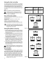
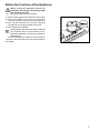
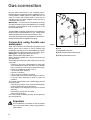
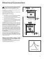
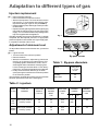
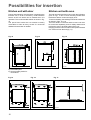
BUILT-IN HOB
ZXS 646 IT
INSTRUCTION BOOKLET
UA
SI
HR
1
Important Safety Information
These warnings are provided in the interest of safety. You MUST read them carefully before
installing or using the appliance.
About Installation, Cleaning
and Maintenance
•
•
•
•
•
•
•
•
•
It is mandatory that all operations required for the
installation are carried out by a qualified or competent
person, in accordance with existing rules and regulations.
Disconnect the appliance from the electrical supply,
before carrying out any cleaning or manteinance work.
Ensure a good ventilation around the appliance. A poor
air supply could cause lack of oxygen.
Ensure that the gas supply complies with the gas type
stated on the identification label, placed near the gas
supply pipe.
Using a gas cooking appliance will produce heat
and moisture in the room which it has been
installed in. Ensure a continuous air supply, keeping
the air vents in good conditions or installing a
cooker hood with discharge tube.
In case of intensive or long time use of the appliance,
make the ventilation more efficient, by opening a
window or increasing the electric exhaust fan
power.
Once you removed all packaging from the appliance,
ensure that it is not damaged and the electric cable is
in perfect conditions. Otherwise, contact your dealer
before proceeding with the installation.
The manufacturer disclaims any responsability
should all the safety measures not be carried out.
Under no circumstances should you attempt to repair
the appliance yourself. Repairs carried out by
unexperienced persons may cause injury or serious
malfunctioning. Refer to your local Service Centre.
Always insist on genuine spare parts.
During Operation
•
It is most important that this instruction book should be
retained with the appliance for future reference. Should
the appliance be sold or transferred, always ensure that
the book is left with the appliance in order that the new
owner can get to know the functions of the appliance and
the relevant warnings.
•
This appliance has been designed for non professional
purpose in private houses only. It is meant to cook edible
foodstuff only and MUST NOT be used for any other
purposes.
It is dangerous to alter the specification in any way.
For hygiene and safety reasons, this appliance should
be kept clean at all times. A build-up of fats or other
foodstuff could result in a fire.
Under no circumstances should you attempt to repair
the appliance yourself. Repairs carried out by
unexperienced persons may cause injury or serious
malfunctioning. Refer to your local Service Centre.
Always insist on genuine spare parts.
Ensure that all control knobs are in the OFF position
when not in use.
Should you connect any electrical tool to a plug near this
•
•
•
•
•2
•
cooking appliance, ensure that electric cables are not
in contact with it and keep them far enough from the
heated parts of this appliance.
If the appliance is out of order, disconnect it from the
electric supply.
Child Safety
•
•
•
This appliance has been designed to be operated by
adults and children under supervision. Young children
MUST NOT be allowed to tamper with the controls or play
near or with the oven.
Accessible parts of this appliance may become hot
when it is in use. Children should be KEPT AWAY until it has
cooled.
This appliance is not intended for use by children or
other persons whose physical, sensory or mental
capabilities or lack of experience and knowledge
prevents them from using the appliance safely
without supervision or instruction by a responsible
person to ensure that they can use the appliance
safely.
Environmental Information
•
•
After installation, please dispose of the packaging with
due regard to safety and the environment.
When disposing of an old appliance, make it unusable,
by cutting off the cable.
The symbol
on the product or on its packaging
indicates that this product may not be treated as household
waste. Instead it shall be handed over to the applicable
collection point for the recycling of electrical and electronic
equipment. By ensuring this product is disposed of correctly,
you will help prevent potential negative consequences for
the environment and human health, which could otherwise
be caused by inappropriate waste handling of this product.
For more detailed information about recycling of this
product, please contact your local city office, your household
waste disposal service or the shop where you purchased
the product.
Guide to Use the instructions
The following symbols will be found in the text to
guide you throughout the Instructions:
Safety Instructions
Step by step instructions for an operation
Hints and Tips
Environmental information
These instructions are only for the countries
stated by the symbol printed on the front cover
of this instruction book.
Contents
For the Installer
For the User
Important Safety Information
2
Technical Data
7
Instruction for the User
3
Instruction for the Installer
7
Cleaning and Maintenance
6
Gas connection
8
Electrical Connection
9
European Guarantee
-
13
This appliance complies with the following
E.E.C. Directives:
2006/95 (Low Voltage Directive);
2004/108 (Electromagnetical Compatibility Directive);
90/396 (Gas Appliances Directive )
and subsequent modifications.
Adaptation to different types of gas
10
Building In
11
Possibilities for insertion
12
MANUFACTURER:
ELECTROLUX ITALIA S.p.A.
C.so Lino Zanussi 30
33080 Porcia (PN) - ITALIA
Instruction for the User
Once the hob has been installed, it is
important to remove any protective materials,
which were put on in the factory.
Hob burners control knobs
The hob burners control knobs are situated on the hob
right hand side. The symbols on the knobs mean that:
there is no gas supply
there is maximum gas supply
there is minimum gas supply
Lighting the burners
For easier lighting, proceed before putting a
pan on the pan support.
To light a burner, push in the relevant knob and
turn it counterclockwise to "maximum position".
After lighting the flame, keep the knob pushed
down for about 5 seconds. This will allow the
"thermocouple" (Fig. 1, lett. D) to be heated and
the safety device to be switched off, otherwise the
gas supply would be interrupted.
Then, check the flame is regular and adjust it as
required.
If you cannot light the flame even after several
attempts, check the "cap" (Fig. 1, lett. A) and the
"crown" (Fig. 1, lett. B) are in the correct position.
To put the flame out, turn the knob to the symbol .
•
Always turn the flame down or put it out before taking
the pans off the burner.
Manual switch-on (in case of interruption of the
electric supply) : approached a flame to the burner
and push in the relevant knob and turn it
counterclockwise to "maximum position".
Fig. 1
FO 0204
A - Burner cap
B - Burner crown
C - Ignition candle
D - Thermocouple
Do not keep the control knob pressed for more
than 15 seconds.
If the burner does not light even after 15 seconds,
release the control knob, turn it the “off” position
and wait for at
least one minute before trying to light the burner
again.
3
Using the hob correctly
To ensure maximum burner efficiency, it is strongly
recommended that you use only pots and pans with a
bottom fitting the size of the burner used, so that flame will
not spread beyond the bottom of the vessel (fig. 2 -a).
It is also advisable, as soon as a liquid starts boiling, to
turn down the flame so that it will barely keep the liquid
simmering.
Use only pans or pots with flat bottom.
Carefully supervise cookings with fats or
oil, since these types of foodstuff can result
in a fire, if over-heated.
Burner
120 mm.
220 mm.
Small (Auxiliary)
80 mm.
160 mm.
To switch on the plates, turn the relevant knob to the
required position.
The plates are regulated by a 7 position switch:
Position 0: off
Position 1: minimum disbursement of heat
Position 6: maximum disbursement of heat
The pilot light signals the connection of the electric plate.
It is important to note that the plate may smoke
and produce a slightly unpleasant odour when used
for the first time. This is quite normal and will
disappear after a short while.
Fig. 2 - a
When cooking by electric, saucepans should have a
thick base and be perfectly flat in order to ensure
total contact with the plate and, consequently, perfect
conduction (Fig. 2-b).
Occasionally, saucepans have a thin bottom and these
loose their shape over a period of time. In this manner
two of the qualities of the electric plate are lost: the
even distribution of heat and the saving of energy.
Cooking time is also lengthier.
As regards the size of the saucepans: for best results,
the plate and the saucepan should have the same
diameter. The diameter of the saucepan may be
slightly larger; a smaller diameter is not advised.
Never leave the plates on without a saucepan! Switch
off the plate just before the end of cooking time. The
heat accumulated by the plate will finish cooking the
food and save energy.
When cooking with fats or oils maximum care
must be taken as these can self-ignite when
over-heated.
Rapid plates
The rapid plates are indicated by a red dot, and will
heat up more quickly than a normal plate. As the red
dots are painted on the plate, they may deteriorate during
use and even disappear completely after a period of time.
This will not affect the performance of the hob.
It is important to note that the plate may smoke
and produce a slightly unpleasant odour when
used for the first time. This is quite normal and will
disappear after a short while.
4
maximum
diameter
Medium (semirapid)
Use of electric plates
Using the plates correctly
minimum
diameter
Fig. 2 - b
Before the First Use of the Appliance
Before using the appliance remove all
packaging, including the advertising labels
and any protective film.
When using the hob for the first time:
1) place on all the plates a pan filled with some water;
2) switch the plates on for about 10 minutes at
“maximum” position until water inside the pans boils;
3) then, turn the control knob to “minumum” and allow
the plates to run for approximately 20 minutes;
4) open a window for ventilation.
During this time, the plates may smoke a little and
an unpleasant odour may be emitted. This is
absolutely normal and is caused by residues of
manufacturing.
Once this operation is carried out, let the plates to
cool down, then clean them with a soft cloth soaked in
warm water.
5
Cleaning and Maintenance
Disconnect the appliance from the electrical
supply, before carrying out any cleaning or
manteinance work.
General cleaning
Wash the enamelled components with warm soapy
water. Never use abrasive cleaners
Frequently wash the "caps" and the "crowns" with hot
soapy water, carefully taking away any built-up of food.
Regularly wipe over the hob top using a soft cloth weel
wrung out in warm water to which a little liquid detergent
has been added. Avoid the use of the following:
- household detergent and bleaches;
- impregnated pads unsuitable for non-stick saucepans;
- steel wool pads;
- bath/sink stain removers.
Should the hob top become heavily soiled, it is
recommended that a proper cleaning product is used.
Fig. 3
FO 2110
Pan supports
Service and original spare parts
The pan supports are dishwasher proof.
If the marks are particularly difficult to remove, use
common non-abrasive cleaners or specific products.
Never use steel wool pads or acids.
This machine, before leaving the factory, has been tested
and studied by many experts and specialists, in order
to give you the best results.
Ignition candle
The electric ignition is obtained through a ceramic
"candle" and a metal electrode (fig.1-lett. C). Keep these
components well clean, to avoid difficult lighting, and
check that the burner crown holes are not obstructed.
Cleaning of the hotplates
Spills on the hotplates should be removed using warm
water and a soft cloth.
Alternatively, wipe the plates with a drop of olive oil on a
kitchen towel (while the plates are still warm).
Periodic Maintenance
Periodically ask your local Service Centre to check the
conditions of the gas supply pipe and the pressure
adjuster, if fitted.
To ensure the good operation of the hob and its safety
features, it is necessary that the taps are periodically
lubricated.
6
Any repair work which needs to be carried out should be
done with the utmost care and attention.
For this reason we reccomend that for any problem you
contact the dealer who sold it to you, or our nearest
authorized Service Centre,
specifying the nature of the
problem and the particular model
which you own. Always Insist on
genuine original spare parts.
Technical Data
Gas Burners Rating
Auxiliary Burner
Semirapid Burner
Appliance Class
Category
1 kW
2 kW
3
II 2H3B/P
Setting
LPG G30/G31 30/37 mbar
Gas connection
G 1/2"
Electric hotplates
Small hotplate
Large hotplate
Ø 145 mm.
Ø 180 mm.
1000 W
2000 W
Electric Supply
230 V ~ 50 Hz
Hob recess dimensions
Length
Width
550 mm.
470 mm.
Instruction for the Installer
The following instructions about installation and
maintenance must be carried out by qualified
personnel in compliance with the regulation in
force.
The side walls of the unit in which the hob is
going to be installed, must not exceed the height
of the working top.
Avoid installing the appliance in the proximity of
inflammable materials (e.g. curtains, tea towels
etc.).
The appliance must be electrically disconnected
before all interventions. If any electric supply to
the appliance is required to carry out the work,
ensure all the necessary precautions are followed.
THE MANUFACTURER WILL NOT ACCEPT
LIABILITY, SHOULD ANY OF THE OTHER SAFETY
INSTRUCTIONS INCORPORATED IN THIS BOOK
OR THE REGULATION IN FORCE BE IGNORED.
7
Gas connection
Choose fixed connections or use a flexible pipe in
stainless steel in compliance with the regulation in force.
If using flexible metallic pipes, be careful they do not
come in contact with mobile parts or they are not
squeezed. Use the same attention when the hob is
combinated with an oven.
IMPORTANT - To ensure a correct operation, a saving
of energy and the long-life of the appliance, the voltage
pressure of the appliance must correspond to the
recommended values.
The adjustable connection is fixed to the comprehensive
ramp by means of a threaded nut GJ 1/2". Interpose the
sealing between the components as shown in fig. 4.
Screw the parts without forcing, adjust the connection in
the required direction and tighten everything.
Connection using flexible non
metal pipes
When the connection can be easily inspected in its full
extent, there is the chance to use a flexible pipe
according to the rules in force. The flexible pipe must be
tightly fixed using clamps according to the rules in force.
Natural gas : use the pipe fitting «D» (Fig. 4).
LPG : use the rubber pipe holder «E».
Always insert the gasket «B». Then proceed with the
gas connection.
The flexible pipe should be made ready for use in such
a way that:
- nowhere it can reach overtemperature, other than
room temperature, higher than 30°C; if the flexible
pipe, to reach the cock, must run behind the range,
it must be installed as shown in Fig. 4;
- it is no longer than 1500 mm;
- it shows no throttles;
- it is not subject to traction or torsion;
- it doesn't get in touch with cutting edges or corners;
- it can be easily inspected in order to check its
condition.
The control of preservation of the flexible pipe consists
in checking that:
- it doesn't show cracks, cuts, marks of burnings both
on the end parts and on its full extent;
- the material is not hardened, but shows its normal
elasticity;
- the fastening clamps are not rusted;
- expiry term is not due.
If one or more abnormalities are seen, do not repair the
pipe, but replace it.
Important
Once installation is complete, check the perfect
seal of every pipe fitting, using a soapy solution,
never a flame
8
Fig. 4
FO 0067
A)
B)
C)
D)
E)
Ramp with ending nut
Seal
Adjustable connection
Rubber pipe holder for Natural gas
Rubber pipe holder for LPG
Electrical Connection
The following instructions about installation
must be carried out by qualified personnel in
compliance with the regulation in force.
YES
RIGID COPPER PIPE OR
FLEXIBLE PIPE IN STAINLESS
STEEL
The appliance is designed to be connected to 230 V
monophase electricity supply.
The connection must be carried out in compliance with
the laws and regulations in force.
Before the appliance is connected:
1) check that the main fuse and the domestic installation
can support the load (see the rating label);
2) check that the power supply is properly earthed in
compliance with the current rules;
3) check the socket or the double pole switch used for
the electrical connection can be easily reached with
the appliance built in the furniture unit.
The appliance is supplied with a connection cable. This
has to be provided with a proper plug, able to support the
load marked on the identification plate. To connect the
plug to the cable, follow the recommendation given in Fig.
5. The plug has to be fitted in a proper socket.
If connecting the appliance directly to the electric system,
it is necessary that you install a double pole switch
between the appliance and the electricity supply, with a
minimum gap of 3 mm. between the switch contacts and
of a type suitable for the required load in compliance with
the current rules.
The connection cable has to be placed in order that, in each
part, it cannot reach a temperature higher than 90 °C.
The brown coloured phase cable (fitted in the terminal
block contact marked with "L") must always be connected
to the network phase.
Fig. 5
FO 0238
Replacement of the voltage cable
Only cable types H05V2V2-F T90 or H05 BB-F (section:
3 x 1,5 mm2) must be used.
The yellow/green earth wire must be approximately 2 cm.
longer than the phase wires (Fig. 6).
Neutral
Earth (yellow/green)
FO 0073
Fig. 6
9
Adaptation to different types of gas
Injectors replacement
• Remove the pan supports.
• Remove the burner's caps and crowns.
• With a socket spanner 7 unscrew and remove the
injectors (Fig. 7), and replace them with the ones
required for the type of gas in use (see table 2).
• Reassemble the parts, following the same procedure backwards.
• Replace the rating label (placed near the gas supply
pipe) with the relevant one for the new type of gas
supply. You can find this label in the package of the
injectors supplied with the appliance.
Should the feeding gas pressure be different or variable
compared with the required pressure, an appropriate
pressure adjuster must be fitted on the gas supply pipe,
in compliance with the rules in force.
Fig. 7
FO 0392
Adjustment of minimum level
Fig. 8
To adjust the minimum level of the burners, proceed as
follows:
• Light the burner.
• Turn the knob on the minimum position.
• Remove the knob.
• With a thin screwdriver, adjust the by-pass screw
(see Fig. 8). If changing from natural gas to LPG,
completely tighten clockwise the screw, until a
small regular flame is obtained. If changing from
LPG to natural gas unscrew about 1/4 turn the bypass screw, until a small regular flame is obtained.
• Finally check the flame does not go out when
quickly turning the knob from the maximum position
to the minimum position.
This procedure can easily be carried out, anyhow the hob
has been positioned or built in the working top.
By-pass screws
Table 1 : By-pass diameters
Burner
Ø By-pass
in 1/100
of mm.
Auxiliary
28
Semi-rapid
32
Table 2 : injectors
TYPE
OF GAS
TYPE OF
BURNER
INJECTORS
MARKS
1/100 mm
NOMINAL
POWER
INPUT
KW
REDUCED
POWER
kW
NOMINAL
POWER
3
m /h
g/h
NOMINAL
PRESSURE
mbar
NATURAL
GAS
G 20
Semi-rapid (medium)
Auxiliary (small)
96
70
2,0
1,0
0,45
0,33
0,190
0,095
-
20
LPG
(Buthane/
Propane)
Semi-rapid (medium)
Auxiliary (small)
71
50
2,0
1,0
0,45
0,33
-
144
72
30
10
Building In
PE
PE
These hobs can be inserted in a built-in kitchen unit
whose depth is between 550 and 600 mm. The hobs
dimensions are shown in the relevant diagram.
The edge of the cut out must have a minimum distance
from the rear wall of 55 mm.
If there are side walls, or sides of the furniture unit near
the hob, the cut out edges must have a minimum
distance of 100 mm.
A
58
Hanging furniture units or hoods must be placed at 650
mm. minimum from the hob.
A
SR
PE
SR
0
= Auxiliary burner
= Semirapid burner
= Electric hotplate
50
0
Dimensions are given in millimeters
Fitting the hob to the worktop
The hobs can be installed in a kitchen unit with an
opening for insertion whose dimensions are shown in fig.
9. To install the hob, proceed as follows:
1) Remove the pan supports, the burners caps and
crowns and turn the hob upside down, taking care the
ignition candles are not damaged in this operation.
2) Place the sealing gasket (supplied with the hob) on
the edges of the cut out, taking care that the sealings
meet without overlapping;
3) Fix the hob with the relevant fixing clamps, supplied
with the accessories bag (fig. 10). The traction of the
screws is able to trace the sealing, any excess of
which can be easily removed.
The edge of the hob forms a double labyrinth seal which
provides a total guarantee against infiltration of liquids.
Fig.9
FO 2098
FO 0199
a
WARNING: When securing the fixing clamp near
the terminal block, always ensure the connection
cable does not come in contact with the edge of
the clamp (see fig. 11).
Fig.10
a) Sealing gasket
YES
NO
A
Fig.11
B
A
B
A) Fixing clamp
B) Connection cable
11
Possibilities for insertion
Kitchen unit with door
Kitchen unit with oven
Proper arrangements must be taken in designing the
furniture unit, in order to avoid any contact with the
bottom of the hob which can be heated when it is
operated. The recommended solution is shown in Fig.
12.
The panel fitted under the hob should be easily
removable to allow an easy access if a technical
assistance intervention is needed.
The hob recess dimensions must comply the indication
given in Figs. 13 and 14 and must be provided with
brackets to allow a continuous supply of air.
To avoid overhating, the building in should be carried out
as shown in Figs. 15 e 16.
The hob's electric connection and the oven's one must
be carried out separately, both for safety reasons and
to allow the oven to be easily taken off the unit.
Hanging furniture units or hoods must be placed at 650
mm. minimum from the hob (fig. 17).
Fig. 13
FO 1013
FO 0947
Fig. 14
595
Fig. 12
FO 0198
a) Removable panel
b) Space possibly useful for
connections
Fig. 15
FO 0939
12
Fig. 16
FO 0938
Fig. 17
FO 2099
European Guarantee
This appliance is guaranteed by Electrolux in each of the countries listed at the back of this user manual, for the
period specified in the appliance guarantee or otherwise by law. If you move from one of these countries to another
of the countries listed below the appliance guarantee will move with you subject to the following qualifications:· The appliance guarantee starts from the date you first purchased the appliance which will be evidenced by
production of a valid purchase document issued by the seller of the appliance.
· The appliance guarantee is for the same period and to the same extent for labour and parts as exists in your
new country of residence for this particular model or range of appliances.
· The appliance guarantee is personal to the original purchaser of the appliance and cannot be transferred to
another user.
· The appliance is installed and used in accordance with instructions issued by Electrolux and is only used within
the home, i.e. is not used for commercial purposes.
· The appliance is installed in accordance with all relevant regulations in force within your new country of
residence.
The provisions of this European Guarantee do not affect any of the rights granted to you by law.
13
14
15
35675-9104 R.B
05/09